99 minute read
CHAPTER 6 OPERATION

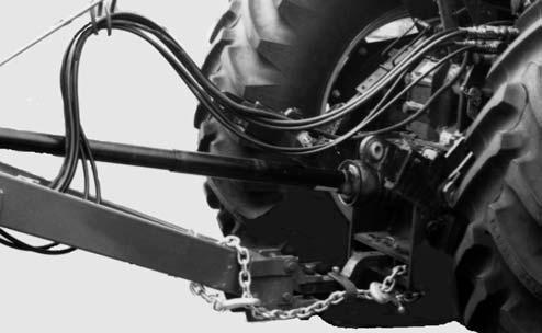
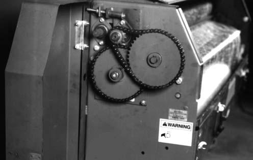
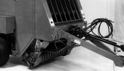
1 – Shuttle Stop
2 – Shuttle Chain Adjustment Bolt
3 – Shuttle Lock in “Storage” Position 4 – Shuttle Chain 5 – Density Cylinder Sprocket 6 – Density Cylinder 7 – Gate Cylinder
8 – Bale Starter Torsion Spring 9 – Scraper Roller Overrunning Clutch Sprocket 10 – 16″ Roller Driven Sprocket 11 – Adjustable Wheel Spindle 12 – 8″ Roller Drive Sprocket 13 – Transmission Drive Sprocket 14 – 8″ Floor Roller Idler 15 – 16″ Floor Roller Idler
16 – Spring-loaded idler
17 – Packing Roller Spring Adjustment
18 – Packing Roll Stop Adjustment Bolt
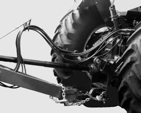
19 – Windguard
20 – Windguard Latch
21 – Left Twine Feed Sensor*
22 – Baler to Tractor Connector
23 – Tractor Battery
24 – Tractor Control Module
25 – Bale Size Sensor*
26 – Implement Module*
27 – Shuttle Return & Full Size Bale Sensor*
28 – Gate Latch Sensor*
*Auto-Electric Models ONLY
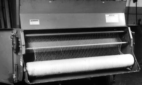
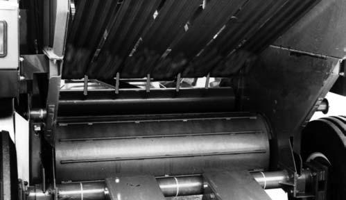
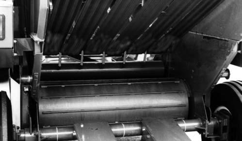
Fig. 22: Component Identification - Left Side
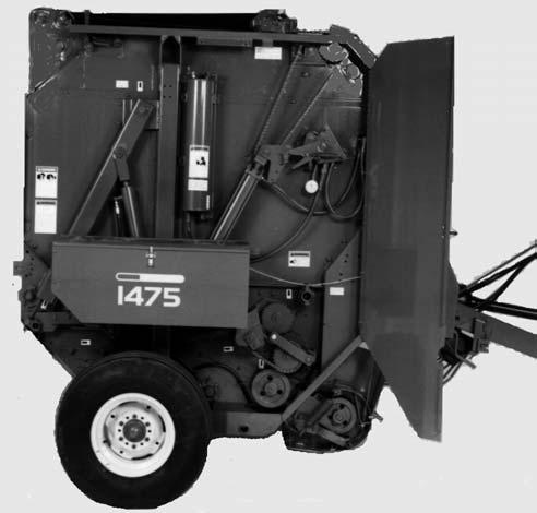
HOW BALER FUNCTIONS (Figs. 22 & 23)
Crop material is picked off the ground by the 4-Tinebar, Closed-style Pickup and delivered to the throat of the unit where it is pressed by the Packing Roller against the Lower Roller. The Rollers then carry the crop to the back of the unit where the crop meets the Belts which are traveling toward the front of the unit. The Belts carry the crop forward and over the top of the lower incoming mat of material until it comes in contact with the Bale Starter Fingers. The Fingers deflect material down into the incoming mat of material to form a roll of crop material or bale core.
As the round core of material gets larger in size, the Bale Starter is lifted from the area to avoid contact with the bale. As the bale increases in size, the additional Belting, required to wrap the bale, is released by the Belt Shuttle as it moves toward the rear of the Baler. Belt tension and bale density control is governed by the Total Density Control (TDC) system. The windrow and driving pattern of the Baler operator determines how well the material is distributed across the bale.
NOTE: It may be necessary to weave from one side of the windrow to the other in order to properly distribute crop into the baling chamber.
On manual control models, when the Bale Size Indicator reaches the preferred size, the twine can be wrapped around the bale. Once tied, the bale is ejected by opening the Gate and the process of forming another bale can be restarted. The maximum bale size is “5” (for RB1475) or “6” (for RB1875),
NOTE: It may be necessary to back up several feet before ejecting the bale to allow room to close and latch the tailgate without contacting the crop windrow.
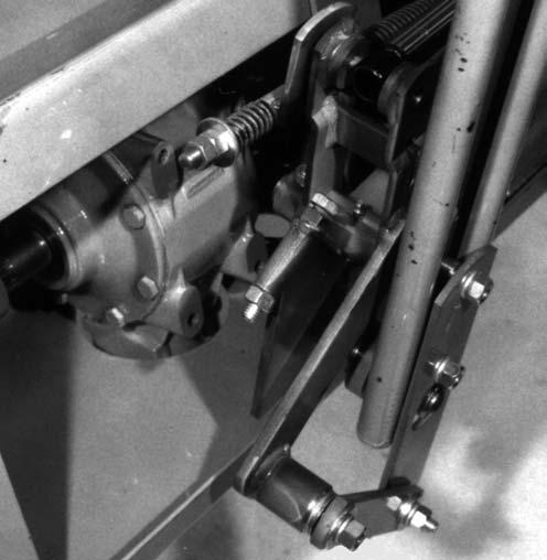
HOW TDC SYSTEM FUNCTIONS (Figs. 24, 25 & 26)
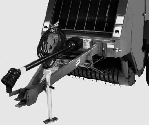
The Belt Tension and subsequent bale density is controlled by the Total Density Control (TDC) system. The major components of this system include a Reservoir, two Density Cylinders, an adjustable Pressure Relief Valve, and a Manifold with a Trip Mechanism. This unique TDC system is self-contained and is completely independent of the tractor hydraulic system. The TDC system supplies a tensioning force to the Belts which, in turn, exerts a compressive force on the forming bale.
During the initial bale forming stage, the force exerted by the Density Cylinders onto the Belts is directly related to the air pressure in the Reservoir. As the bale increases in size, the additional Belting required is released by the Belt Shuttle as it moves toward the rear of the Baler. This rearward travel of the Belt Shuttle extends the Density Cylinders and forces hydraulic fluid out of the Cylinders, through a Manifold and into the Reservoir. This additional fluid further compresses the air in the Reservoir and causes an increase of pressure resulting in Belt tension.
1
2
3
4 – Pressure Reading of 140 to 150 PSI (980 to 1050 kPa) (Shuttle Returned)
5 – Adjustable Relief Valve Setting 150 to 450 PSI for RB1475 & 150 to 550 PSI for RB1875 (1050 to 3,150 kPa for RB1475, 1050 to 3850 kPa for RB1875)
6 – To Left Cylinder
7 – Shuttle Cylinder
As the Cylinders continue to extend, the Valve Trip Mechanism is contacted by the Trip Spacer on the Trip Arm of the right Density Cylinder Clevis. As the Valve Trip Mechanism is triggered, the free flow path through the Manifold is blocked off and the hydraulic fluid is redirected through the adjustable Pressure Relief Valve on its way to the Reservoir. The Relief Valve works to create a pressure differential between the Density Cylinders and the Reservoir. This means that the fluid pressure in the Density Cylinders has to reach a preset value above the pressure in the Reservoir before the Relief Valve will relieve and allow the fluid to pass through to the Reservoir.
As the bale continues to grow and the Cylinders continue to extend, the TDC system continues to function in the manner previously described. When the bale is ejected from the Baler, the pressure in the line from the Density Cylinders to the Relief Valve drops below the pressure in the Reservoir. This causes a reverse flow of hydraulic fluid from the Reservoir back into the Density Cylinders. The Cylinders are retracted which in turn restores the Shuttle, the Belts and the Valve Trip Mechanism to their original positions. The TDC system is once again ready to start forming another bale.
BALE FORMATION & STORAGE TIPS
The following information provides guidelines for using the Round Baler to get the most out of your crop and investment.
1 – Air Pressure
2 – Pressurized Reservoir
3 – Oil
4 – Pressure Reading of 170 to 290 PSI (1190 to 2030 kPa)
5 – Adjustable Relief Valve Setting 150 to 450 PSI for RB1475 & 150 to 550 PSI for RB1875 (1050 to 3,150 kPa for RB1475, 1050 to 3850 kPa for RB1875)
6 – To Left Cylinder
7 – Shuttle Cylinder
Fig. 25: Bale Building
(Beyond Core Formation) Detail
1 – Air Pressure
2 – Pressurized Reservoir
3 – Oil
4 – Pressure Reading of 290 to 290 PSI (1050 to 2030 kPa)
5 – Adjustable Relief Valve Setting 150 to 450 PSI for RB1475 & 1050 to 550 PSI for RB1875 (1050 to 3,150 kPa for RB1475, 1050 to 3850 kPa for RB1875)
6 – 15 PSI (105 kPa)
7 – To Left Cylinder
8 – Shuttle Cylinder
Fig. 26: Bale Ejecting & Shuttle Return Detail
A – Small Core with High Density Crop (See Curve 1)
B – Small Core with Low Density Crop (See Curve 2)
C – Large Core with High Density Crop (See Curve 3)
D – Large Core with Low Density Crop (See Curve 4)
1 – Curve for Core Formation “A”
2 – Curve for Core Formation “B”
3 – Curve for Core Formation “C”
4 – Curve for Core Formation “D”
5 – Outer Crop (Relief Pressure-controlled)
6 – Core Formation (Air Pressure-controlled)
7 – Increasing Bale Diameter
8 – Increasing TDC System Bale Forming Pressure
Optimum Conditions & Bale Density (Fig. 27)
Optimum haying conditions are a combination of crop maturity and moisture content. Because of changing weather conditions, NOT all hay can be baled under ideal circumstances. The TDC system enables the Baler to adapt to these less than ideal conditions. In particular, the density of the bales can be adjusted to be more compatible with baling conditions.
As moisture content increases, the bale density can be decreased. Using the illustration and table provided for a reference, several types of bales can be formed by altering either or both the Trip Spacer on the Trip Arm which is connected to the right Density Cylinder or the Relief Valve pressure setting. Changing the Trip Spacer location to one of the other lower holes, progressively increases the core diameter by delaying activation of the Valve Trip Mechanism.
Bale density can be adjusted for different crop conditions and moisture contents by adjusting the Relief Valve setting. Turning the End Disc assembly clockwise into the Valve Body increases the Relief Pressure and bale density. The adjusted setting can then be locked in place by turning the Locking Ring clockwise until it is snug against the Valve Body.
Bale Handling & Storage WARNING
Bales made with a Round Baler are LARGE, CYLINDRICAL and HEAVY! Serious personal injury or property damage could result if the bales are not carefully and properly handled. MAKE SURE the bale will not roll when ejected from the baler. BE SURE that the tractor used with any bale handler is large enough to safely handle the weight of the bales. Front or rear counter-weights may be required. Using a bucket–style front end loader to move bales creates a hazard, because the bale can roll out of the bucket and down the loader arms onto the operator. Generally, agricultural tractor Roll-over Protective Structures (2–Post ROPS) are not intended to protect against falling bales. Do NOT lift round bales with the standard loader unless you have proper bale restraining devices.
Because the bales are cylindrical and very heavy, special care MUST be exercised when ejecting them and storing them to keep them from starting to roll. When the bales are moved, make sure that the original bottom of the bale stays at the bottom. When moving bales to a storage area, observe the following recommendations to minimize crop loss:
1.Select a well-drained area with complete exposure to the sunlight.
2.Place the axis of the bales north and south so the sun can dry out the cylindrical surface of the bale as it travels from east to west.
3.Where space allows, set several bales in a row with their ends pushed tightly together to form a long cylinder. Make sure that you do NOT form a water dam using too many bales in a row without skipping a space. Make sure to always maintain a clear path for the water to travel away from the bales.
4.Keep the rows of bales far enough apart so that one row will NOT overshadow the adjoining row and cut down on exposure to full sunlight.
5.When bales are stored outside in conditions of exceptionally high rainfall (especially driving rains), spoilage due to water penetration can be reduced by placing the shingled cylindrical surface of the bale in the direction of prevailing rain or wind. The shingled surface can be determined by running your hand along the edge of the bale. On the shingled surface, your hand will slide smoothly. The unshingled surface will offer more resistance to your hand movement.
Baling
After transporting the Baler to the field, adjust the Pickup height according to crop conditions and land contour; refer to the Pickup Flotation topic in the Adjustment chapter of this manual for details. The Baler Pickup should be run as high off the ground as possible while still being able to completely pick up all of the crop.
IMPORTANT: The Pickup assembly MUST be carried off the ground. Running the Pickup too low to the ground will result in excessive Tine wear or breakage and possible damage to the Pickup Stripper Bands and Headers, Cam and Cam Bearings.
Move the Baler into position with respect to the windrow and BE SURE to check the path in front of the Pickup and ahead of the Baler before starting to bale. Then, start the PTO, bring the tractor RPM up to the desired operating speed and begin baling.
If the windrow has been prepared to less than the full width of the Bale Chamber, it will be necessary to drive the Baler in a weaving fashion to fill the Chamber and start the bale core. If the windrow has been prepared for the full width of the Pickup, either 45 to 52″ (1143 to 1321 mm) for an RB1475 or 61 to 68″ (1549 to 1727 mm) for an RB1875, the Baler can be driven straight down the windrow while observing that the bale starts and continues to form properly. To obtain the most uniform bales, the windrow should, wherever possible, be made at or slightly larger than the Bale Chamber width.
When baling a windrow which is about 1/2 the width of the Bale Chamber and after the core has started, stop the weaving process and drive straight with the windrow entering the Pickup as far to one side as possible. Continue driving the Baler with the windrow entering on one side until the rotating bale is approximately 3 to 4″ (76 to 102 mm) higher on one side than the other. Then, quickly cross over so that the windrow enters on the other side of the Pickup and continue filling that side until it is 3 to 4″ (76 to 102 mm) higher than the other side. Continue crossing over from side to side until a full-sized bale is formed.
When baling a windrow which matches the full width of the Bale Chamber, drive straight down the windrow until the desired full-sized bale is formed.
IMPORTANT: Continuous feeding of material provides for smoother starting and better bale formation. Avoid non-cylindrical bales and bales with loosely packed outside edges. Both conditions can allow the Belts to fall off the ends of the bale and possibly tear out the Belt Lacing Hooks. In addition, this type of bale will weather poorly. Proper material preparation is a very important factor in making good-shaped bales. Refer to the Preparing for Field Operation chapter of this manual for further details.
Baylage (High Moisture Hay) (RB1475 Only)
NOTE: Anyone experimenting with this type of storage procedure, for the first time, should do so with limited samples, to minimize potential losses.
NOTE: Due to the extremely HEAVY bale that results from high moisture baling, we recommend that bale sizes be kept under a 4 ft (1.2 m) diameter. It is further recommended that Balage baling be limited to using only an RB1475 Baler and equipping it with an accessory Silage Scraper Kit. Refer to the Optional Features & Accessories chapter for ordering information.
BALE SIZE VISUAL INDICATOR (MANUAL & AUTOMATIC TWINE CONTROL MODELS) (Fig. 28)
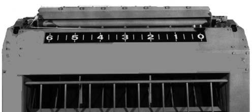
The Bale is full-size when it reaches 5 feet (1.5 m) in diameter for the RB1475 Baler or 6 feet (1.8 m) in diameter for the RB1875 Baler. As a matter of personal preference, the bale forming process can be stopped at any time before this size. For this reason, the Bale Size Visual Indicator is provided as a visual aid to forming consistent sized bales.
OVERFILL PROTECTION (Figs. 22 & 23)
The Baler is designed with an Overfill Clutch mechanism which automatically stops the Pickup when the bale becomes oversized. If the bale becomes oversized, the Shuttle will activate the Overfill Clutch Actuator which is linked by a Cable to the Pickup Drive to stop the Pickup and prevent damaging the Baler. When this happens, simply back the Baler out of the windrow and tie or wrap the bale in the normal manner.
MANUAL TWINE WRAP (Figs. 28 & 29)
NOTE: The procedure described is the manual sequence. The entire process of wrapping the bale with twine is done from the tractor seat.
The position of the Pointer on the Bale Size Indicator can be used as a fairly accurate gauge for forming the desired size bale. When the desired size bale is formed, stop Baler forward travel. Then, swing the Twine Arm so that it is straight back.
NOTE: The Twine Arm is actuated by moving the Twine Arm Positioning Switch to the “FORWARD” position to move the Twine Arm from right to left. Moving the Twine Arm Positioning Switch to the “REV” (Reverse) position moves the Twine Arm from left to right.
NOTE: By moving the Twine Arm to the middle of the Baler, appropriate lengths of twine are brought out for starting to wrap a new bale.
Then, drive forward again to take in a small amount of material to start feeding the twine into the Baler.
Danger
NEVER attempt to clean or manually feed the baler when it is running. Material feeds into the baler faster than you can react to release it. You may become entangled in moving belts, pick-up or rollers. Failure to heed can result in death or serious injury.
When the twine can be seen moving into the Twine Arm, stop Baler forward travel. Allow the twine to make at least one full wrap in this location and then move the Twine Arm to the left side.
NOTE: Moving the Twine Arm all the way to the left engages and locks the Twine Cutoff Jaws in the open position.
NOTE: Normally, the bale can be adequately tied with two wraps of twine on the left side, several wraps across the center of the bale and two wraps on the right side. If the material being baled is slippery, it will be beneficial to place two wraps of twine on the center of the bale before moving to the left side in order to prevent the twine from sliding off the end of the bale. It may also be necessary to adjust the positions of the end wraps depending on the crop being baled.
When the Twine Arm returns all the way to the right, the Twine Jaws will snap closed and the twine will be cut. The wrapped bale can now be ejected from the Baler and baling can resume.
AUTOMATIC TWINE WRAP SYSTEM Features
The Auto Twine Wrap Control System exhibits the following features and characteristics:
1.AUTO/MANUAL Mode Selection - fully automatic tie system or manual tie system.
2.Continuous moving Twine Arm distributes twine in a helical pattern across the bale.
3.A daily bale counter which can be reset to Zero (0)
4.A lifetime bale counter which cannot be reset
5.The error message “SEt” is displayed when the twine wrapping system is not functioning properly (Refer to the Troubleshooting chapter).
6.Two spaced audible tones are sounded when the tie cycle starts.
7.The message “tIE” is displayed while the system is in the twine tie sequence.
8.One audible tone is sounded and the message “OPEn” “GAtE” is displayed when the tie sequence is through and the Baler is ready for the bale to be discharged. The message “OPEn” “GAtE” remains displayed until the bale is discharged.
9.One audible tone is sounded when the Tailgate is first opened and then repeated every eight seconds while the Tailgate remains open.
10.Two quick audible tones are sounded when the Tailgate is closed and latched.
Operation
The Control Module is a monitor and controller for the Twine Arm. When a bale is formed, a sequence is started that drives the Twine Arm across the face of the bale. The twine is applied in a predetermined helical pattern across the face of the bale and is designed to apply extra twine on each bale end.
Bales can be tied in a manual or fully automatic mode. The Control Module also keeps a daily and lifetime count of bales made.
NOTE: This Auto Twine Control is NOT intended for use on Balers equipped with Quick Wrap.
Controls Control Module (Fig. 30)
POWER Switch (Fig. 31)
Actuator Switch (Fig. 33)
This Toggle Switch is used to direct power to the Actuator to manually EXTEND or RETRACT the Twine Arm.
NOTE: The Mode Switch (Fig. 32) MUST BE set to MANUAL for this Switch to function.
Fig. 31: Power Switch
This Toggle Switch is used to power up and shut down the Auto Twine System.
On
Move the Switch Handle to the right to turn Control Module on and power up the auto twine control system.
Off
Move the Switch Handle to the left to power down the control system. This will cause the display to go blank and the control system will not accept any signals from any sensors.
Mode Switch (Fig. 32)
This Toggle Switch is used to direct power to either the SELECT Key for automatic control (AUTO mode) or to the Actuator Switch for manual control (MANUAL mode) of the Auto Twine System.
To SELECT Switch
Auto
To Actuator Switch
Fig. 32: Mode Switch
Move the Switch Handle to the left to direct power to the SELECT Key for automatic twine control.
Manual
Move the Switch Handle to the right to direct power to the Actuator Switch.
From MANUAL Position of Mode Switch
Fig. 33: Actuator Switch
(Manual Mode Operation, ONLY)
Extend
Move and hold the Switch Handle to the right to extend the Actuator Rod and cause the Twine Arm to move toward the left side of the Baler.
Retract
Move and hold the Switch Handle to the left to retract the Actuator Rod and cause the Twine Arm to move toward the right side of the Baler.
Neutral
Release the Switch Handle to STOP actuator movement. Switch Handle will automatically return to center position when released.
SELECT Key (Fig. 34)
NOTE: Mode Switch. Fig. 32, must be set to AUTO for the SELECT Key to function.
The SELECT Key is used to advance the Digital Display one channel each time it is pressed. Each of the five channels is used to control a different segment of the tie cycle. The active channel is indicated by the chevron that points toward the associated icon shown below the display. The value for each channel (except channel 1) can be changed by pressing the INCREASE or DECREASE Key. If a change is not made to the active channel within 5 seconds, the display will default back to channel 1. Channel 1 is the default channel and it indicates the daily bale count and the condition of the Tailgate (Open or Closed).
NOTE: See separate topics later in this chapter for information about the purpose and settings for each channel and for the INCREASE and DECREASE Keys.
Lifetime Bale Count
The SELECT Key is also used to view the lifetime bale count. To show lifetime bale count since installation of the Control Module, press and hold down the SELECT Key for 5 seconds.
INCREASE & DECREASE Keys (See Fig. 34)
While in “AUTO” mode and NOT on channel 1, press either Key to change the value for the function being displayed. (See separate topics later in this chapter for information about the purpose and settings for each channel.)
NOTE: To reset the Bale Count to “0”, press and hold the DECREASE and INCREASE Keys simultaneously.
Digital Displays Default Reset
To return all of the channels back to the factory set defaults, press and hold the INCREASE and DECREASE Keys simultaneously while moving the POWER Switch Lever to ON.
Press and hold the SELECT Switch for 5 seconds to have the Display show total bales made since the Control Module was first installed. Range 0–9999.
NOTE: The Tailgate Open and Closed indicators on the Display are disabled while total bale count is displayed.
NOTE: Press the SELECT Key, Fig. 34, to advance from one channel (display) to the next.
Channel 1 – Daily Bale Count –Default Display (Fig. 35)
Bale Count Display when Tailgate is Closed
Bale Count Display when Tailgate is Open
The Daily Bale Count displays the number of bales made since the last time the counter was set to zero
(Range is 0-999). This is the default display and is active whenever: the Control Module is turned on, is NOT in a “tie” sequence, or the SELECT Key has NOT been pressed within the last 5 seconds to change to a different channel.
This display also indicates the condition of the Tailgate. When the Tailgate is “closed”, the bottom segment of the leftmost digit is displayed (next to the icon showing a “closed” tailgate – see top illustration in Fig. 35); likewise, when the Tailgate is “open”, the top segment of the leftmost digit is displayed (next to the icon showing an “open” tailgate with a discharged bale – see bottom illustration in Fig. 35).
To reset the Daily Bale Counter to Zero, press and hold the DECREASE and INCREASE Keys, simultaneously, to reset the Daily Bale Count display to ZERO.
NOTE: Numerical values (marked with an *) for channels 2 and 3 are arbitrary values; they ONLY represent a range, NOT an actual count.
Channel 2 – Twine Density (Spacing of Wraps Across Bale)
(Fig. 36)
Press DECREASE Key for more spacing between wraps (fewer overall wraps) or INCREASE Key for less spacing between wraps (more overall wraps).
Range is 0–12* in 1 step increments; Default is 6.
NOTE: The Twine Arm moves faster across the face of the bale as the setting approaches “0”.
* Arbitrary Numbers
Channel 3 –
37)
Press DECREASE for fewer wraps or INCREASE for more wraps.
Range is 0–9* in 1 step increments; Default is 3).
NOTE: The Twine Arm pauses for a shorter period of time at each bale end as the setting approaches “0”.
* Arbitrary Numbers
Channel 4 – Twine Arm Pause (Delay for Twine to Start on Bale) (Fig. 38)
Press the DECREASE Key for a shorter delay or the INCREASE Key for a longer delay.
Range 0–20 seconds in 1 second increments; Default is 2 seconds.
NOTE: The Twine Arm pause time is shorter as the setting approaches “0”.
Channel 5 – Twine Arm Position (Position of Arm for Twine to Start on Bale) (Fig. 39)
a. E1 - Out of twine or only one twine placed on bale b. E2 - Out of netting c. E3 - Twine/Netting NOT started d. E5 - Twine Arm obstruction e. E6 - Shuttle NOT returned f. E7 - Twine or Netting started prematurely g. E8 - End Wrap Pause Switch Adjustment/ Faulty h. E9 - Twine/Netting NOT cut off
Fig. 39: Channel 5 – Twine Arm Position
Press the DECREASE Switch to cause the Twine Arm to stop further toward the center of the Baler or the INCREASE Switch to cause the Twine Arm to stop further toward the left side of the Baler. Range 1–7 seconds in 0.5 second increments; Default is 4 seconds.
NOTE: The position where the Twine Arm pauses is closer to the right side of the baler as the setting approaches “0”. For RB1475 Balers, DO NOT set above 5.0 seconds or the twine tie sequence will stop and the “SET” error message will display.
NOTE: Any changes made while in the AUTO mode will be preserved in memory.
AUTOMATIC BALE CONTROL SYSTEM Features
The Baler Wrap Control System exhibits the following features and characteristics:
1.A daily bale count which is resettable to Zero (0)
2.A life time count which is NOT resettable
3.Programmable to specific Gehl Baler models
4.Bale size selection from 3 feet (.9 m) to the maximum bale size in 6 inch (152 mm) increments
5.Exclusive Twine/Quick Wrap Netting selection from the tractor seat
6.Audible pulsing Beeper sounds and an Error Code is displayed when bale growth and wrapping systems are not functioning properly. The following lists all of the “Error Message” codes and what the codes mean: i. E10 - Insufficient (low) voltage or (low) amperage
7.MANUAL/AUTO Selection - fully automatic tie system or manual tie system
8.Cycle feature to manually start the auto tie cycle at anytime.
9.Feature displaying the per cent (%) of Netting used from the roll (resettable)
10.Adjustable number (#) of wraps - for both twine or net from the Control Module
11.Automatic shutdown after 30 minutes if NO Keypad entries or input entries are detected from the baler sensors
12.Enlarging Bar Graph grows as bale size grows
13.One audible tone sounds when the bale size gets to within 6 inches of the selected bale size; at this time, the Bar Graph also starts to flash
14.Three audible tones sound when the bale reaches the selected bale size to mark the start of the tieing/ wrapping cycle
15.Two audible tones sound when the tieing/wrapping cycle has been successfully completed
16.One audible tone sounds and the “GO” Arrow displays when baling can resume
17.Flashing “CYCLE” Icon appears when tieing/ wrapping cycle starts or when “CYCLE” Key is touched
18.Flashing “CYCLE” Icon goes solid ON when Twine/Netting is starting to feed
19.“TAILGATE OPEN” Icon appears when Tailgate is open
20.To obtain a bale count (and a “GO” Arrow), the following three things MUST happen: a.Successful Tie b.Tailgate properly opens and closes c.Shuttle MUST return to its “Home” position
21.Even displacement of wrapping material regardless of baler rpm and bale size
Operating System
The following are the typical Keypad selections to activate and operate the Electronic Bale Wrap Control System:
NOTE: If, after initial “Power Up”, the display on the Tractor Module lights up and goes blank within a few seconds:
1.Check that the power cord from the Baler is connected to the tractor and all connections are clean and tight.
2.Faulty Implement Module. See Dealer.
After “Power Up”, the system will automatically default to the settings as they were before “Power Down”. Keypad activations always require that the Keypad be pressed and temporarily held until a beep is heard and/or the Display changes.
“Power” Key
Press and hold the “Power” Key to power up (turn on) the control system.
To power down (turn off) the control system, press the “Power” Key. This will cause the display to go blank and the control system will not accept any signals from the cab module or any sensors. However, bale wrapping information is preserved in memory (see Note, below).
NOTE: It is recommended to power down (turn off) the control system by pressing the “Power” Key anytime an interruption to the control system power is anticipated. This will preserve the current bale size information by storing it in memory; if the control system power is interrupted without powering down or in any other way (such as power loss due to starting the tractor engine or disconnecting the Power Cable), the current bale size information and the Bale Size Bar Graph will be lost.
NOTE: As noted above, pressing the “Power” Key will make the control system inoperable. However, this does NOT eliminate all power consumption. If the Baler is going to be idle for a week or more and remain hitched to the tractor, it is recommended that the Power Cord between the tractor and the Baler be separated to prevent draining of the tractor battery.
“Enter” Key
Whenever a key is pushed within the top two rows (Command Keys) of the keypad, a corresponding icon will flash in the display. If no further commands are entered by pressing a key on the keypad within 5 seconds, the flashing icon will stop and the system will return to its previous settings. In order for the system to understand and remember a new command, the command must be followed by pushing the “ENTER” key. If the “ENTER” key is not pushed within 5 seconds, the system will return to its previous setting.
Pressing the “ENTER” key will also mute the audible alarm when an error message is displayed. Muting the alarm will NOT clear the display of the error code until the error is corrected. Once the error is corrected, pressing the “ENTER” key will clear the display.
“Bale Size” Key
NOTE: The current mode of wrapping can be identified by the icon in the top right center of the display; either for NET mode or for TWINE mode.
To alternate between TWINE and NET modes for making changes:
To adjust the bale diameter:
1.Press the “BALE SIZE” key
The current programmed bale size will be shown on the display and the word “SIZE” will be flashing on and off at the lower left hand side of the display.
2.Press the “+” key to increase bale size or press the “–” key to decrease bale size.
The Bale diameter shown in the display will respond to key entries and will increase or decrease in 6″ increments. Likewise, the limiting icon on the Bar Graph will move up and down and align itself with the selected bale size diameter.
3.Press the “ENTER” key to save the programming change made to the bale size.
Key
1.To enact a change in the wrapping mode, press the “TWINE/NET” key. The alternate wrapping mode should begin flashing in the top right center of the display.
2.Verify that the flashing icon represents the desired wrapping mode. If it does, press “ENTER” to save. The flashing icon should have switched to solid.
NOTE: The control will not switch from twine to net if it is not programmed with the correct code for a Quick Wrap baler. See Machine Operating Codes topic in this chapter for Baler codes.
Amount of Wraps
The values for wrapping a bale are different for twine than they are for net. When adjusting the number of wraps, you are only changing the value of wraps that pertain to the wrapping mode for which you are programmed. For example, if programmed to twine, only the number of twine wraps change. If programmed to net, only the number of net wraps change. If the control is switched from twine to net, the system will remember any previous setting for the number of net wraps. The same holds true when switching from net to twine.
To adjust the number of wraps (Auto Mode Only), press either the “+” or “–” key. A numeric value will appear in the display along with the flashing icon “WRAPS”. To increase the numeric value (number of wraps), continue to push the “+” key. To decrease the number of wraps, push the “–” key.
When in the “TWINE” Mode, the numeric value is the approximate number of wraps of twine placed across the circumference of the bale. The value increases and decreases by increments of 1 between 1 and 10, with 10 being the greatest amount of twine.
NOTE: Settings 4 and 5 will apply the same amount of wraps (approximately four wraps) across the bale. However, a setting of 4 or lower will place approximately 2-1/2 end wraps while a setting of 5 or higher will place approximately 3-1/2 end wraps. On Settings 1 and 10, the Twine Arm will NOT stop when travelling from the left side to the right side when applying twine.
When in the “NET” mode, the numeric value on the display is the approximate number of times the net is wrapped around the circumference of the bale (One wrap equals one time around the bale). The system can be adjusted in 0.25 wrap increments between 1.25 and 9.75.
“Cycle” Key
To start the wrapping cycle early (Auto Mode Only):
1.Press the “CYCLE” key. The flashing cycle icon should be visible in the upper right hand corner of the display. This indicates that the control system has been switched to the wrapping mode.
2.Press the “ENTER” key. This confirms that you want to start the wrapping cycle. The actuators for either the netting or twine arm should have started and continued in the automatic wrapping cycle.
Bale Count (Daily)
To clear the daily count, press and hold the “–” key and the “+” key simultaneously until a “0” appears on the display.
Bale Count (Lifetime)
To check the lifetime count, press the “ENTER” key and hold it until the first number (1000’s digit) is displayed. Then, release the “ENTER” key before the second number (hundreds) is displayed.
NOTE: The display will alternate between two sets of numbers. For a count under 1000, the display will first show “0” (the 1000’s digit) and the second display will be the count under 1,000. For counts over 1,000, the 1st display will be the number of 1000’s and the second display will be the count under 1,000.
Example:
A lifetime count of 13,568 would alternately display as 13 (for the 1000’s count) and 568 (for the count under 1,000).
Operation in the Manual Mode
The primary function of the Manual Mode is to manually control the extension and retraction of the twine arm actuator or Quick Wrap actuator. Typically, this is required to route twine through the twine arm or service the baler.
The Manual Mode can be used when building and wrapping a bale, should the Auto Mode become enabled. When operating in the Manual Mode, many of the monitoring sensors on the baler are electronically switched off. The Manual Mode will allow the operator to select twine or net, change bale size, and count bales. The bale size Bar Graph will function the same as in the Auto Mode as will the tailgate open and close icon with the go arrow.
NOTE: If the bale size sensor or the tailgate sensor were to become disabled, the display will not function properly. However, it will still be possible to operate the actuators manually, providing there is sufficient power to the implement control module and the actuators.
NOTE: The maximum lifetime count can be 999,999. To clear the display of the lifetime count mode, press “ENTER” while the second set of numbers (hundreds) is on the display.
Switching From Auto To Manual Mode
Through the course of daily operation in the “AUTOmatic” mode, it may become necessary to switch to the “MANUAL” mode to perform a troubleshooting sequence, an adjustment or restart the system after a particular Error Message has been acknowledged and rectified. To change from “AUTO” to “MANUAL”, power-up (if NOT already power-up), press the “MANUAL/AUTO” key, hear a single beep and observe that the Display shows the MAN Icon flashing. Then, press the “ENTER” key to lock-in the “MANUAL” mode.
The Manual Mode does not notify the operator when the wrapping is started. The flashing cycle icon will never stay on solid. The flashing icon is only used as an indicator to inform the operator that the manual tie system is in process and that the actuator is not in the home position.
Manual Mode Twine Arm Extension & Retraction
When in the “MANUAL” mode, the following steps can be carried out to extend and retract the Twine Arm in order to facilitate twine routing or whatever needs to be manually accomplished:
1.Press and hold the (+) “EXTEND” key, hear a beep, and observe that the “CYCLE” Icon comes on and continues to flash as the Twine Arm continues to move away from the “home” position. Release the key to stop Twine Arm movement.
2.Press and hold the (–) “RETRACT” key, hear a beep, and observe that the “CYCLE” Icon comes on and continues to flash as the Twine Arm continues to move toward the “home” position. Release the key to stop Twine Arm movement.
1.Press and hold the (+) “EXTEND” key, hear a beep, and observe that the “CYCLE” Icon comes on and continues to flash as the Wrap Control Actuator Shaft continues to move out. Release the key to stop Actuator movement.
2.Press and hold the (–) “RETRACT” key, hear a beep, and observe that the “CYCLE” Icon comes on and continues to flash as the Wrap Control Actuator Shaft continues to retract. Release the key to stop Actuator movement.
NOTE: The Twine Arm must have stalled in the Home Position before the flashing cycle icon will disappear. The system will not accept any further commands until the “CYCLE” icon is cleared from the display.
Manual Quick Wrap Activation & De-activation
NOTE: The Net Wrap Actuator must have stalled in the Home Position before the flashing cycle icon will disappear. The system will not accept any further commands until the “CYCLE” icon is cleared from the display.
% Of Net Left
When operating in the Net Mode, the control system will keep track of the amount of net being consumed, which takes into account the number of wraps and bale diameter. The system works best when using the suggested net supplied by Gehl dealers. Reset the % of net left value shown each time you add a new roll of net. To do this, push the “CYCLE” key twice and hold for 5 seconds the second time.
When in the “MANUAL” mode, the following steps can be carried out to extend and retract the Wrap Control Actuator whenever this needs to be manually accomplished:
To show the % of net left on the display, push the cycle twice. The value on the display will represent the amount of net left on the net roll.
Normal Baling In Automatic Cycle
The following information displays the normal baling cycle from indications by the Tractor Module. With all of the desired settings established, recognize the following circumstances and events that could occur.
At Start, Baler and Go Arrow
Signify Ready to Bale
Bar Graph Starts To Build To
Pre-selected Size
Bar Graph Flashes when Bale Diameter is 6″ less than selected bale size. {Horn Emits (1) Beep}
Solid Bar Graph {Horn Emits (3) Beeps} when bale reaches predetermined size
Go Arrow Disappears
Cycle Icon Flashes When Tie Cycle Starts
Cycle Icon Goes Solid When Netting or Both Twines Start Wrapping on Bale {Horn Emits (1) Beep}
Horn Emits (2) Beeps When Tie Cycle Finishes
Open Baler Gate and Eject Bale. Bar Graph resets to 0
Close Baler Gate After Bale is Ejected
Go Arrow Re-appears after Tailgate is latched and Shuttle has returned. {Horn Emits (1) Beep} & Bale count increases by one
Normal Baling In Automatic Cycle With Errors
The following information displays the normal baling cycle with potential error Displays interjected in the various stages of the baling cycle when they are most likely to be displayed by the Tractor Module. With all of the desired settings established, recognize the following circumstances that could occur.
Possible
Possible
At Start, Baler and Go Arrow
Signify Ready to Bale
Bar Graph Starts To Build To Pre-selected Size
Possible
Bar Graph Flashes 6 inches Before Pre-selected Size. {System Emits (1) Beep}
Possible Solid Bar Graph {System Emits (3) Beeps}
Possible
Go Arrow Disappears
Possible
Cycle Icon Flashes When Tie
Cycle Starts
Cycle Icon Goes Solid Netting or Twine Starts
Possible
System Emits (2) Beeps When Tie Cycle Finishes
Possible
Open Baler Gate and Eject Bale
Possible
Close Baler Gate After Bale is Ejected
Possible
System Cycle Is Completed, Go Arrow Re-appears {System Emits (1) Beep}
MANUALLY BUILDING A BALE TO TEST AUTO–ELECTRIC CONTROL SYSTEM Preparation
Under certain conditions it may be necessary to test the Auto–Electric Control System by manually simulating the building of a bale. To simulate building a bale, proceed as follows:
1.Secure the Baler in a safe, stable and level location to avoid any inadvertent repositioning of the machine. The Tailgate should be in the closed and latched position.
2.Disconnect the Baler Driveline from the tractor and place the tractor end of the Driveline onto the Driveline Support provided on the Baler.
Required Equipment
3.The following equipment is need to be able to perform the simulated bale: a.A 12 Volt DC power supply capable of delivering a 20 ampere flow. b.Two people capable of spinning the Twine Wheels. c.One small magnet.
4.Connect the Auto–Electric Control System to the 12 Volt DC power supply. Check that all Wiring Harnesses are securely fastened.
5.Become familiar with the Auto–Electric Control System as described in the Operation chapter of this Operator’s Manual. Refer to the Operation and Troubleshooting chapters of this manual if problems occur during the following procedure.
6.Power up the Auto–Electric Control System by pressing and holding the Power Key.
Machine Operating Codes
7.Check that the Control System is programmed for the correct Baler model. Press “+” and “MANUAL/AUTO” simultaneously (NOTE: + will increase the code and – will decrease the code). Select “+” or “–” until the correct code that matches your Baler appears in the display. See the following table to determine the correct code. Press “ENTER” Key.
Code # Baler Model & Wrap System cd1 1475 with Twine Wrap ONLY cd2 1475 with both Twine & Quick Wrap cd5 1875 with Twine Wrap ONLY cd6 1875 with both Twine & Quick Wrap
Select “AUTO” Mode
8.If the word “AUTO” does not appear on the top of the display, select the “MANUAL/AUTO” Key. After the flashing “AUTO” icon appears on the display, select the “ENTER”Key. The display should appear as follows;
NOTE: It is important to have an arrow displayed in front of the “BALER” icon to indicate that everything is functioning properly.
Program “BALE SIZE”
9.Select the “BALE SIZE” Key. The words “BALE SIZE” should appear flashing in the lower portion of the display. Push “+” or “–” (“+” to increase, “–” to decrease) until 3.00 appears in the display. Press the “ENTER” Key within 5 seconds to save the 3.00 foot bale diameter value.
Select Wrapping System
10.If the Twine icon is not showing on the top of the display, push the “TWINE/NET” Key and the Twine icon should appear on the top of the display. Press the “ENTER” Key within 5 seconds to save the Twine Tieing mode.
Program Twine Wrap Density
11.Press the “–” Key. This will display the current value for the twine application and a flashing “WRAP” icon will appear on the bottom of the display. Use the “–” Key to toggle the twine density to 1. Press the “ENTER” Key within 5 seconds to save the value.
Building a Bale
12.If the “GO ARROW” appears in the front of the Baler icon, you can proceed to build a bale. To build a bale, toggle the Bale Size Sensor up and down. The Bale Size Sensor is located on the left side of the Baler in the top front corner. The Sensor pivots about the Shuttle Stabilizer Sprocket. Each time the red light on the cord end of of the Sensor flashes, a count is being registered. After 9 counts, the Bar Graph on the display should begin to grow. Continue to toggle the Sensor. When the Bar Graph reaches the 2-1/2 foot mark, one (1) audible signal will sound and the the Bar Graph will flash on and off. Keep toggling the Bale Size Sensor until three (3) audible signals are sounded and a flashing “CYCLE” icon appears in the upper right hand corner of the display (the “GO ARROW” will also disappear). At this point, the Twine Arm should extend and point directly to the back of the Baler while pausing.
13.The Twine Arm will remain at the pause position until one of the following conditions occur: a.If both twines have started on the bale (accomplished only when both Twine Wheels have rotated simultaneously), the Twine Arm will advance to the left side of the Baler to apply end wraps and then proceed to “home” while making intermittent stops. b.If, within 15 seconds, only one twine starts on the bale (accomplished when only one Twine Wheel rotated), the Twine Arm will still wrap the bale, but with only one string. Once the wrapping mode is completed, an E–1 error code will display on the control indications that the bale was wrapped with only one twine. The operator then has the option to correct the problem and rewrap the bale by pressing the “CYCLE” and “ENTER” keys or to eject the bale with only a single twine. c.If, after 15 seconds, neither twine has started on the bale (accomplished when neither Twine Wheel rotated), an E–3 error message will display on the control and the Twine Arm will return to the home position.
Open Tailgate
14.Simulate opening the Tailgate by passing a magnet past the Tailgate switch. The “TAILGATE” icon should appear and then disappear when the magnet is removed. The Bale Size Bar Graph should have also disappeared, the Bale Count incremented by one, and the “GO ARROW” icon should have reappeared in front of the “BALER” icon.
15.Repeat Steps 12., 13. & 14., if desired.
QUICK WRAP GENERAL INFORMATION (Fig. 40)
By design, either 1475 or 1875 Auto-Electric Balers can be operated with either the Quick Wrap System or the Twine Tie (Wrap) System.
NOTE: In either case, only one or the other bale wrapping system can be operated at a time. Refer to this Operator’s Manual for Twine Tie System operational information.

Quick Wrap Roll Installation (Figs. 41 & 42)
Warning
When installing the net roll, take care to avoid pinching your fingers between the rubber drive rollers.
Quick Wrap Roll Selection
NOTE: For best results, it is recommended that ONLY high quality, GEHL approved Quick Wrap material be used.
Quick Wrap Roll Care
Quick Wrap material should always be properly protected from moisture and damage. Snags in the material can result in unpredictable performance, poor bale appearance and reduced weatherability. BE SURE to store the Quick Wrap material in a cool, dry place away from direct sunlight. The protective covering should remain intact until the roll is placed onto the Quick Wrap Tailgate.
1 – Netting Routed Into Pinch Rolls
2 – Plastic Tube Passed Through Netting Roll and Engaged in Net Roll Pivots On Each End
3 – Rewrap bale in “Raised” Position
1.On the Tractor Module, perform the steps required to fully extend the Control Actuator as listed in the Manual Quick Wrap Activation & De-activation topic of this chapter.
2.Exercise the MANDATORY SAFETY SHUTDOWN PROCEDURE (Page 10).
3.Place Net Roll on Tailgate (Lower Shield).
4.Install Plastic Pipe through center of Net Roll Core, center Roll on the Plastic Pipe and place the Roll and Pipe into the Net Pivots on each end of Tailgate.
5.Rotate the Lower Shield and Net Roll into place.
6.Rotate Rewrap Bar away from Rubber Pinch Roll and lock upward.
7.Route Net end over Stationary Bar and up to Rubber Roller as shown.
8.Stretch the Net over entire length of Rubber Roller. Secure Net between Rollers by rotating Roller no more than one revolution.
9.Rotate Rewrap Bar toward Rubber Pinch Roll and lock in place. (Dashed Position)
10.Close Shields and secure Latches before resuming operation.
11.On the Tractor Module, perform the steps required to fully retract the Control Actuator as listed in the Manual Quick Wrap Activation & De-activation topic of this chapter.
QUICK WRAP OPERATION Principle of Operation
While operating the Baler to build the bale, the wrapping system is NOT operating. When the bale reaches 6″ (152mm) before the predetermined size, the Tractor Module Bale Size Bar Graph will flash and a single beep will be heard. Continue baling until the Bale Size Bar Graph becomes a solid line and the System beeps three times. Stop forward travel IMMEDIATELY and back up a few feet. After shifting the tractor to park or neutral, continue to run the PTO. The Tractor Module Go Arrow will disappear and the “CYCLE” icon will begin to flash.
NOTE: Forward travel MUST be stopped IMMEDIATELY to prevent the crop from being placed on the outside of the Net material.
When the wrapping cycle begins, the Electric Actuator will extend causing the Knife Blade Holder to rotate the Blades away from the Front Guide assembly and release the end of the Netting. In addition, as the Blade Holder rotates, it drives the Rubber Drive Roller by means of a one-way overrunning clutch, to advance the Netting towards the Feeder Belts. The Feeder Belts will sandwich the Netting between the (bale forming) Belts and the Feeder Belts and carry the Netting toward the bale. The “CYCLE” icon will go solid. As the net is feeding onto the bale, the one-way clutch will be overrunning on the blade holder shaft. The last 1-1/2″ (37 mm) of the Actuator stroke will cause the Pivot Plate to compress the Spring on the Brake Tension Arm. The Brake will then increase the drag on the Drive Roll and increase the Netting tension. There is also a Sensor mounted on the right side of the Steel Drive Roll which measures the amount of Netting placed on the bale. When the correct amount of Netting has been distributed, the Actuator will be retracted. While the Actuator is being retracted, the Strap (Fig. 43) will hold Spring tension to maintain proper Netting tension. At the end of the Actuator retraction cycle, the Brake will be released, the Blade will cut and hold the Netting and the “CYCLE” icon Indicator will extinguish and the System will beep twice indicating the tying cycle is completed. NOTE: It may be necessary to back up several feet before ejecting the bale to allow room to close and latch the Tailgate without contacting the crop windrow.
The bale can now be ejected and the bale formation process can be restarted. As the End Gate is opened and the bale is ejected, the “BALER” icon displays an open End Gate. As the End Gate is closed, the “BALER” icon displays a closed End Gate. When the System is recycled and ready to bale, the “BALER” icon will display the Go Arrow and the System will beep once.
The Baler can be operated with either a conventional Twine Tie system or the Quick Wrap system. For the Twine Tie system, refer to information provided in the Auto-Electric Control topic of the Operation chapter of this Operator’s Manual.
Wrapping The Bale
At least two complete wraps should be used for normal baling conditions. More wraps may be required for different conditions or to increase bale weatherability. To adjust the number of wraps, depress the “+” or “–” key on the Tractor Module. A numeric value indicating the approximate number of wraps will appear in the display along with the flashing “WRAPS” icon. To increase the number of wraps per bale, depress the “+” key, followed by the “ENTER” key. To decrease the number of wraps per bale, depress the “–” key followed by the “ENTER” key. The amount of wraps per bale can be adjusted from 1.25 to 9.75 wraps in 0.25 wrap increments.
When the bale size is changed, it WILL NOT be necessary to adjust the amount of wraps to compensate for the change in size. The system automatically compensates for the changes in bale size and PTO speed.
Use the following charts as a guide for selecting the number of wraps for a given crop:
Table of Recommended 1475 Wraps
Unplugging (Figs. 41 thru 45)
To unplug the Quick Wrap Attachment, proceed as follows:
1 – Adjusting Bolt (Drive Roller) Tension
2 – 093457 Keep Door Closed WARNING Decal
3 – Compression Spring Adjusted to 1-3/4 to 1-7/8” (44 to 46 mm) (Pinch Roll Tension)
4 – Strap
Fig. 43: Right Side Door Opened
1.Exercise the MANDATORY SAFETY SHUTDOWN PROCEDURE (Page 10).
Table of Recommended 1875 Wraps
1 – Compression Spring Adjusted to 1-3/4 to 1-7/8” (44 to 46 mm) (Pinch Roll Tension)
2 – 093457 Keep Door Closed WARNING Decal
3 – Adjusting Bolt (Drive Roller) Tension
4 – Sprocket with One-Way Clutch
Fig. 44: Left Side Door Opened
2.Locate the source of the plugging. The most likely place to look is in the area of the Quick Wrap Drive Roller and Knife. If Netting should wrap around the Rubber Drive Roller, the Actuator should be in the fully retracted position before attempting to unwrap the Rubber Drive Roller. It is best to cut the Netting the entire length of the Rollers. BE SURE NOT to cut into or damage the Rubber Drive Roller. After the Netting is cut, rotate the Rubber Drive Roller by hand while pulling the cut Netting free from the Roller. It may also be neces- sary to remove the Knife Shield (Fig. 41) and Rear Guide Assembly to access the plugged area. Check to make sure that the Chute area, between the Drive Rollers and the Feeder Belts, is free from obstructions, allowing the Netting to drop down to the Feeder Belts. If necessary, re-install the Netting following the Quick Wrap Roll Installation procedure in this chapter.
Material Removal From Pinch Rollers (Figs. 43 & 44)
Perform the following steps if the Pinch Rollers become wrapped with Netting:
1.Remove the wrapped material by gathering the ends in your hand and pulling.
2.Check the Rollers for any rough edges or protrusions and file down, if necessary.
NOTE: It may be necessary to readjust the Drive Roller Chain if the Pinch Roller tension has changed.
3.Reroute the Net end per the detailed information provided in Fig. 41 and on the decal located inside the Tailgate cover.
4.Close all Shields and secure all Latches.
Ejecting The Bale Warning
Bales made with the Round Baler are LARGE, CYLINDRICAL and HEAVY! When ejected on a flat surface, the momentum of the bale coming off the bale discharge ramps, could carry the bale as far as 10 feet (3 m) behind the baler. On a hill or incline, this distance could be much farther. Serious personal injury or property damage could result if the bale is ejected toward a sloping surface and allowed to roll away uncontrolled!
3.As required, the Rear Guide Assembly should be positioned so that a 1/8 to 3/16″ (4 to 5 mm) gap exists between the Rubber Drive Roller and the Rear Guide Assembly. Then, reinstall and resecure all Shields in their correct positions and, if necessary, adjust proper Pinch Roller Compression Spring tension, on both ends of the Roller, before resuming operation.
IMPORTANT: When removing the wrapped (plugging) material from the Rollers, NEVER cut into Rubber Roller or Belts with a knife. Cuts in Roller or Belts will cause more frequent wrapping problems and necessitate Roller and/or Belt replacement.
The following procedure should be followed, in sequence as described, for ejecting a bale:
1.Stop the PTO (if desired) and back the Baler a short distance away from the windrow.
NOTE: Stopping the PTO, while opening the Rear Gate, will result in a neater looking bale.
2.Activate the tractor hydraulic control lever and fully extend Gate Cylinders to open Rear Gate.
3.If necessary, engage the PTO at a very low RPM and the bale will roll off the lower Rollers.
4.With the PTO running at low RPM, drive the Baler ahead and close the Rear Gate by retracting the Gate Cylinders.
IMPORTANT: BE SURE to fully retract the Gate Cylinders to allow the Gate Latches to engage and lock. The PTO should be kept running while closing the Gate to reduce the possibility of Belt damage and to help prevent the Bale Starter from hanging up on the Belts. Before proceeding to start forming another bale, check to see that the Bale Starter is in the “down” position.
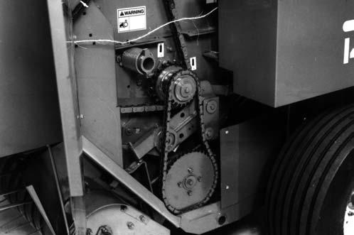
BALE COUNTER (Fig. 46) (Manual Twine Wrap System Only)
The Manual Control Baler is provided with a Bale Counter which indicates the number of times the Gate has been opened to discharge a bale. The Bale Counter is located behind the large Hinged Covers on the right side of the Baler.
ALWAYS use genuine GEHL replacement service parts to assure safe operation of the Baler.
IMPORTANT: To prevent the Pilot Shaft from seizing, the Shear Flange MUST BE GREASED before a new Shear Bolt is installed and the Baler is operated. Refer to the Lubrication chapter for details. BE SURE to remove the cause of the overload before restarting the Baler.
Four extra Drive Line Shear Bolts and Lock Nuts are provided in the Shear Bolt Holder which is located inside the Left Twine Box.
NOTE: Refer to the Optional Features and Accessories chapter of this manual for part number to order additional Shear Bolts.

OVERLOAD PROTECTION SHEAR BOLTS (Fig. 47)
The Baler Drive Line is protected with one 1/4 x 1-1/2″ Shear Bolt, sheared through the base of the Bolt Head.
On 540 RPM model Balers, replacement Grade L9, 1/4 x 1-1/2″ Shear Bolts are available in packaged quantities of (8) per package by ordering part number 095141.
On 1000 RPM model Balers, replacement Grade 5, 1/4 x 1-1/2″ Shear Bolts are available in packaged quantities of (8) per package by ordering part number 900084.
NOTE: In order to achieve proper Bolt shearing, the Shear Bolt Must be installed so that the Bolt shears through the body of the Bolt and not the threads. See Figure 47.
UNPLUGGING & TRASH REMOVAL (Figs. 48, 49 & 50)
If the Baler becomes plugged, the following procedure MUST be used to safely clear the Baler:
1.Back out of the windrow.
2.Disengage the tractor PTO and open the Tailgate.
3.Exercise the MANDATORY SAFETY SHUTDOWN PROCEDURE (Page 10).
Danger
ALWAYS exercise the MANDATORY SAFETY SHUTDOWN PROCEDURE before unplugging or removing trash from the baler.
4.Lock Tailgate open by turning or depressing Gate Cylinder Lockout Valve (See Figs. 5 & 7).
5.Remove the Windguard. The Windguard is a quick disconnecting Guard that can be removed by pulling out and rotating the Windguard Retaining Lever 90°. The Windguard Retaining Lever is located on each side of the Hitch.
6.Pull out loose material from on top of plugged material.
7.When the plug occurred, the Pickup probably continued to run and balled up material on top of the Pickup. Pull the material out from the underside of the in-going windrow between the windrow and the Pickup.
8.When the material becomes hard to pull out/off of the Pickup, place the Reversing Wrench on the Cross Shaft and press downwards on the Wrench (Fig. 49). This will rotate the Pickup and Packing Rolls backwards, backing the material out of the pinch points between the Packing Roll and Pickup.
9.If you have been successful in unplugging the Baler in Step 8., proceed to Step 10. Occasionally you may be unable to reverse the Baler by hand using the Reversing Wrench. In some cases, it will be necessary to eject the partially completed bale in order to gain access to the inside of the Baler. When this occurs, the following steps MUST be followed: a.Remove the Reversing Wrench and return it to its proper storage position. b.Reconnect the PTO disconnected in Step 3. c.Start tractor, engage PTO and eject the partial bale that is formed in the Chamber. The partial bale can be unrolled and re–baled. d.Again exercise the MANDATORY SAFETY SHUTDOWN PROCEDURE (Page 10). e.With the baling chamber cleared, go under the raised and locked Tailgate and remove as much material as possible from the rear of the Baler. Now, using a bar or long wooden pole, bump material from between the Packing Rolls, forward, toward the tractor. NEVER use your hands or feet to clear crop from this position.
Warning
NEVER go under a raised tailgate without first placing the gate cylinder lockout valve in the locked position. See Figs. 5 & 7 for details.
Warning
DO NOT put your hands or feet between the packing roll and lower feed roll. NEVER use your hands or feet to dislodge crop from between the packing roll and lower feed roll. The packing roll is spring loaded downward and will entrap you.
10.After material is unplugged from the Packing Roll/Pickup area, remove any trash that may have built up on top of the belts or on top of the Starter Finger Assembly.
11.Rotate the Starter Finger Assembly upward by hand making sure that none of the Fingers make contact with the Stripper Roll. If any of the Fingers touch the Stripper Roll, they MUST be straightened BEFORE operation can continue.
12.AFTER unplugging, replace the Windguard, place the Gate Cylinder Lockout Valve in the open position and return the Reversing Wrench to its proper storage position.
Warning
ALWAYS remove the reversing wrench from the cross shaft and return it to its storage BEFORE resuming baler operation.
13.Go through the proper start-up procedure, engage tractor PTO at a low RPM and close and latch the Tailgate.

NOTE: If the Baler is equipped with an AutoElectric Control System, the “GO ARROW” icon MUST be visible on the Tractor Control Module BEFORE baling can resume. If the “GO ARROW” icon is NOT visible, with the PTO running, open and close the Tailgate again.
If obstruction is ahead of the Packing Roller but NOT wrapped on the Roller, check to see if the Pickup V-Belt is slipping and that the Windguard Tines are restricted from being raised higher than the center of the Packing Roller. Also, try varying your ground and PTO speeds to find a more suitable combination for the crop being baled. This condition can be encountered when baling dry straw, cane or corn stalks. To improve operation in these crops and conditions, a Packing Roller Lagging K Lit is available. See the Optional Features & Accessories chapter of this manual for additional information.
Chapter 7 Adjustments
Warning
BEFORE adjusting this unit, exercise the MANDATORY SAFETY SHUTDOWN PROCEDURE (page 10).
AXLE HEIGHT (Fig. 51)
The Baler Axle height can be adjusted to four different levels by repositioning and/or rotating the Spindle assemblies. The factory set height shown is appropriate for most normal field conditions. By rotating the Spindle assemblies 180°, the Baler can be lowered approximately 3-3/4″ (95 mm). This setting may be useful when using a tractor with a high drawbar ground clearance. The Baler is shipped in the second highest possible setting.
Warning
Bales made with the Round Baler are LARGE, CYLINDRICAL and HEAVY! When ejected on a flat surface, the momentum of the bale, coming off the bale discharge ramps, could carry the bale as far as 10 feet (3 m) behind the baler. On a hill or incline, this distance could be much farther. Serious personal injury or property damage could result if the bale is ejected toward a sloping surface and allowed to roll away uncontrolled!
BALE STARTER (Figs. 52 & 53)
The Bale Starter device is a set of Fingers that are located between the Belts and behind the Packing Roller. They deflect material and keep it from coming out over the top of and wrapping on the Packing Roller, when starting a bale. The Fingers are part of a movable assembly which is held by Pivoting Links and positioned by a Roller. Springs on each side of the movable assembly return the assembly to a starting position after each bale is ejected. The Roller rides on the Belts and is positioned by the bale.

IMPORTANT: Before starting to form each new bale, look back at the Baler to make sure the Bale Starter Assembly has returned to its starting position. It is possible that material which is wedged in the Links and worn Pivot Bushings or bent linkages can cause the Starter to hang up.

BALE DISCHARGE RAMPS (Fig. 51)
Bale Discharge Ramps are mounted to the back of the Baler Axle and provided to facilitate ejecting a formed and tied bale. To accommodate different crop and field conditions, the Ramps can be mounted in either of four locations, using the holes provided. When baling certain wet crops, it may also be necessary to remove the Ramps to facilitate ejecting the bale.
BELT GUARD (Fig. 54)
The Front Belt Guard should be maintained at a position of 1/8 to 1/4″ (3 to 6 mm) away from the Belts.

Warning
NEVER operate the baler unless the front belt guard is in place and properly adjusted.
CHAIN IDLERS (Fig. 55)
The Baler has only one adjustable Spring-loaded Idler which is located on the Roller Drive. This adjustment is provided to compensate for normal Chain wear. The Idler tension should be checked after every 50 hours of operation and readjusted, when required. The Idler tension is controlled by a Compression Spring that is adjusted to a length of 6-3/4 to 8″ (172 to 203 mm). A clearance of 2″ (51 mm) between the Mounting Bracket and the Spring Guide Head must also be maintained.
1 – 6-3/4 to 8″ (172 to 203 mm) Compressed Spring Length
2 – 2″ (51 mm) Exposed Spring Guide Length
The remaining Chain Drives have spring loaded idlers that are not adjustable.
GATE LATCH LIFT RODS (Fig. 56)
To properly adjust the Gate Latch Lift Rods on either side of the Gate, simply close the Gate and adjust the position of the nut on each Rod so that, with the Gate Hooks resting on the Locking pins, there is a 1/16″ (1.5 mm) clearance between the Nuts and Barrel Spacers on each side of the Gate. Then, open the Gate and close it again to check for correct latching; readjust if necessary. For additional information, refer to the following Gate Stop topic.
GATE STOPS (Fig. 57)
The position of the Gate Stops, which are located on each side of the Baler Frame, can be adjusted by adding or removing Shims. Gate Stop adjustment is only required if some of the Gate components have been replaced. If necessary, shim each side so that, with the Gate closed, the Gate Latches are ahead of the Latch Pins by a measured distance of 1/8″ (3 mm).
1 – Gate End Roller Adjustment Bolts
2 – Lower Belt Guide
3 – End Roller
4 – Right Support Arm
5 – Gate Latch
OVERRUNNING CLUTCH SPROCKET (Fig. 59)
NOTE: After Gate Stops have been adjusted, it may also be necessary to readjust the Gate End Roller position. Refer back to the Gate End Roller topic in the next paragraph.
GATE END ROLLER (Fig. 58)
The Gate End Roller can be adjusted by means of the 1/2″ Bolts (3 for 1475 or 2 for 1875) and (1) 5/16″ Bolt on each side of the Gate. The 1/2″ Bolts are installed in slots and the 5/16″ Bolt can be positioned in any one of a series of holes to vary the position of the Roller. The Roller should be adjusted and maintained at a position of 1/2 to 1″ (13 to 25 mm) from the 16″ Lower Drive Roller. This distance should be increased to 1 to 1-1/2″ (25 to 38 mm) for Balers with the Quick Wrap.
NOTE: The Tailgate MUST be tight against the stops before making adjustment. (See Fig. 57)
IMPORTANT: BE SURE that the Roller is set to the same position on both sides of the Gate, as determined by the 5/16″ Bolt pattern. Also, BE SURE that the Right and Left Gate End Roller Support Arms are kept parallel to each other to insure proper Belt tracking.
The Scraper Roller Overrunning Clutch Sprocket assembly gives positive drive to the Roller while allowing for slight differences in the Roller and Belt speeds. To check for freedom of rotation, with the Baler empty, shuttle locks engaged, and Baler disconnected from the tractor, use a 3/4″ wrench and rotate the cap screw clockwise. The Overrunning Clutch should rotate without rotating any of the other drives. The Clutch is a self-contained unit and can be removed by removing the retaining cap screw.
NOTE: If the Clutch needs to be removed, block Gears on the opposite side of the Baler with a block of wood.
PACKING ROLLER CLEARANCE (Figs. 59 & 62)
The purpose of the Packing Roller is to compress the material which is entering between it and the 8″ Lower Roller. The Packing Roller is spring-loaded and driven from the left side of the machine. Clearance between the lower 8″ Roller and the Packing Roller should be set at 1/4″ (6 mm). This setting is made with the 1/2″ Bolts on the end of the Packing Roller Roll Arms on both sides of the Baler. This clearance should be checked on a routine basis every 100 hours. The Packing Roller Tension Spring lengths, on both sides of the machine, should be set to 9″ (229 mm). For lighter, fluffier crops, the clearance should be opened up and the spring tension should be reduced.
IMPORTANT: The Spring which places tension on the Packing Roller is guided by a Rod with a threaded end. The threads are provided to enable Spring installation in a compressed state. Make sure that the Nut on the threaded Rod is NOT holding the Packing Roller open which could result in damage to the Spring Bracket.
PICKUP (Fig. 60)
The Baler Pickup should be run as high off the ground as possible while still being able to completely pick up all of the crop. A Hand Crank is provided to raise and lower the Pickup. If a Hydraulic Lift Kit is installed, the lower limit of the Pickup is controlled by the Hand Crank. To set clearance, lower the Hand Crank and Hydraulic Lift Cylinder all the way. Set ground clearance with the manual Hand Crank. The Pickup height can also be adjusted by repositioning the Lift Rods (Fig. 63) into a different hole location. This adjustment may be required if the axle and Hitch Tongue have been positioned in the extreme higher or lower position.
NOTE: The Hand Crank setting overrides the Hydraulic Lift Cylinder if the Lift Cylinder is retracted.
NOTE: The Pickup is raised by turning the Hand Crank in a clockwise direction and lowered by turning the Hand Crank in a counterclockwise direction.
PICKUP FLOTATION SPRING (Fig. 61)
The Pickup Flotation Spring is located on the front right side of the Baler. The flotation is set at the factory for a Baler not equipped with Crowder Wheels. The Extension Spring should be stretched to 11″ (280 mm) Hook to Hook when the Pickup is in the “up” position.

If Crowder Wheels are added to the Baler, it will be necessary to increase the spring tension to achieve the desired Pickup flotation.
PICKUP DRIVE (Fig. 62)
The Pickup is driven by a V-Belt from the 8″ Lower Roller. The Belt Drive will slip in the event of an overload. Spring tension on the Idler can be changed by repositioning the Spring Hooks and adjusting the Bracket on the lower back end of the Spring. from the V-Belt. If deflection is more than 2″ (51 mm), readjust Cable clamping point. Cable tension should be checked on a routine basis every 50 hours of operation.
NOTE: V-Belt wear and stretching should be checked on a periodic basis to avoid affecting Overfill Clutch mechanism operation.
IMPORTANT: Excessive Cable tension will mean inadequate V-Belt tension and result in excessive V-Belt wear and Pickup slippage. Too little Cable tension will cause the Overfill Clutch to malfunction and thus NOT protect the Baler. The first bale made, after the Overfill Clutch mechanism is adjusted, should be observed in its final stages with a cautious eye to insure that the mechanism is functioning properly.
WINDGUARD (Fig. 63)
The Windguard for the Pickup has a Limit Stop adjustment. The Limit Stop adjustment consists of two 5/8″ Hexagon Head Cap Screws located on either side of the hitch frame. The Cap Screws are used to set the upper limits of Windguard travel. Normal settings will restrict the Windguard Tines from being raised any higher than the center of the Packing Roller.
Warning
NEVER operate the baler unless the windguard is in place and properly adjusted.
Overfill Clutch (Fig. 62)
The Overfill Clutch mechanism is linked to the Pickup Drive and serves to protect the Baler if it becomes filled beyond design capacity. Readjustment of the Clutch mechanism may be required due to stretching of the V-Belt or Overfill Clutch linkage Cable. To make the adjustment, first make sure the Pickup is set to its operating height. Then, loosen the 3/8″ Hexagon Nut which clamps the Cable to the Pickup V-Belt Idler Arm. Pull on the Cable until the Idler moves and backs off slightly and then retighten the Nut.

Check to see if the Overfill Clutch linkage Cable is too loose by pulling down on the Cable at the upper rear of the Baler. The Cable, when pulled down, should deflect downward less than 2″ (51 mm) from the Frame channel before the Pickup V-Belt Idler has started to move away
SCRAPER (Figs. 52 & 64)
The Lower Drive (Scraper) Roller for the Belts is provided with an adjustable full-width Scraper to help prevent material build-up on the Roller. The Scraper MUST be set close to enable full-width cleaning. To adjust the Scraper Blade, loosen the 5/16″ attaching hardware on the bottom of the Blade. Then, tap the Blade into contact with a 1/16″ (1.5 mm) piece of shim stock against the Roller. Then, tightly secure the 5/16″ hardware. The Blade itself will wear and may require replacement after a period of extended Baler use. Contact your GEHL dealer for the replacement Blade part number.
IMPORTANT: Inspect the Scraper adjustment on a routine basis every 50 hours of operation. If the Scraper is NOT adjusted correctly, material will build up on the Roller and cause excessive horsepower requirements.
In certain short or very dry straws or grass conditions, bale starting may be improved by slackening the Belts during the core formation stage. The Shuttle Stops are provided to enable slackening the Belts, when required. Rotate the Shuttle Stop Bolt on each end of the Shuttle assembly equally to move the Shuttle rearward. 1″ (25 mm) of rearward Shuttle movement results in approximately 4″ (102 mm) of slack in the Belts.
SQUARING BELT SHUTTLE (Figs. 62 & 65)
It is essential that the Belt Shuttle be square with the Baler Frame and the Belt Tracking Roller be properly adjusted (per topic titled “Belt Tracking & Alignment”) so that the Belts track evenly. To check for Shuttle squareness, measure from a crossmember on the top front of the Baler to the right and left end of one of the Shuttle Roller Tubes. To square the Belt Shuttle, have the Baler empty and the Rear Gate closed. Adjust squareness with the Bolt on the left end of the Shuttle. If the Adjustment Bolt will NOT square the Belt Shuttle, it will be necessary to change the Index position of the Keyed Sprockets that connect the left and right Density Cylinder Loading Chains. Use the following procedure for adjustment:
1.Determine the direction in which the Cylinder Loading Chain needs to be adjusted. Remember that the two Sprockets for the Chain tension are keyed to a common Shaft.
2.Depressurize the TDC system. Fully loosen or remove the Valve Stem located on top of the Reservoir. DO NOT retighten until ready to pressurize.
3.Remove the Trip Spacer from the Cylinder Trip Arm. This is done to prevent accidental actuation of the Valve Trip Mechanism (covered later in this chapter).
4.Advance the No. 60 Cylinder Loading Chain the necessary amount and readjust belt to square Shuttle.
5.Replace and/or tighten Valve Stem and pressurize to 140-150 PSI (980–1050 kPa).
6.Replace the Trip Spacer on the Trip Arm. Check to make sure that it will contact the spring loaded Valve Trip Mechanism when baling resumes.
Twine Tie System
Twine Placement (Figs. 66 & 67)
To adjust twine placement on the left-hand side of the Baler:
1.Extend the Actuator until the Twine Arm approaches the left side.
2.Loosen the Jam Nut on the Stop Bolt located on the left side of the Twine Tie Frame Assembly.
3.Extend the Stop Bolt to stop the Twine Arm closer to the center of the bale and retract the Stop Bolt to allow the Twine arm to travel closer to the left side of the bale.
4.Secure the adjustment by tightening the Jam Nut.
1 – Jam Nuts on End of Spring Slide Rod
2 – Actuator Fully Extended

3 – Twine Arm
4 – End Wrap Pause Switch Trip Bracket (Automatic Bale Control Models Only, Early Style)
5 – End Wrap Pause Switch Assembly (Automatic Bale Control Models Only, Early Style)
Twine Tension (Fig. 68) (Manual & Automatic Twine Balers)
The twine tensioning device is located on either side of the bale behind the front side doors. To increase the twine tension, rotate the insulator so the twine route follows a “Z” shaped path.
Twine Tail Length (Fig. 67)
To change the length of the twine tails, adjust the Jam Nuts on the end of the Spring Slide Rod. Losening the adjustment lengthens the tails and tightening the adjustment shortens the tails.
NOTE: It is possible to loosen the Jam Nuts so far that the Clamp Jaws will not clamp twine. Verify Clamp Jaw operation before resuming baling.
1 – Least Tension
2 – Medium Tension
3 – Maximum Tension
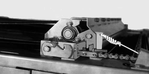
Clamp Jaws (Figs. 67 & 69)
Latch Position
To properly adjust the Clamp Jaw Latch position:
5.Fully extend the Actuator. Then, adjust the Spring Slide Rod so the Clamp Jaw Pivot Rod rotates below the Catch on the Trip assembly. When this position is obtained, tighten the Jam Nuts.
Latch Tension
To adjust the Clamp Jaw Latch tension:
6.Rotate the Lock Nut on the Clamp Jaw Pivot Rod. The tighter the Spring is compressed, the greater the tension on the twine. Adjust the Spring to a length of 1-1/2″ (38 mm).
Tracking & Alignment (Figs. 62, 70 & 71)
NOTE: It may be desirable to install Clamp Jaws with the flat edge up if problems occur using plastic twine.
Manually Opening Clamp Jaws (Fig. 69)
At times, it may be necessary to open the Clamp Jaws to insert or clear the twine. To open the Jaws, place a 3/4″ box or open end wrench on the two 1/2″ Jam Nuts on the Clamp Jaw Pivot Rod and turn. Figure 69 shows an early production Clamp Jaw Pivot Rod with a single Lock Nut.
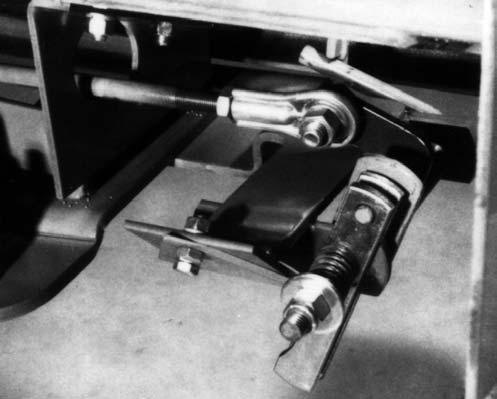
Bale Forming Belts
Tension Adjustment (Figs. 54 & 62)
The tension of the Belts and subsequent bale density is controlled by the hydraulic TDC system. Belt tension can be varied by changing the Relief Valve pressure setting. Belt tension and bale density is increased by turning the Valve Cartridge End Disc clockwise into the Cartridge. To obtain the proper setting, rotate the End Disc clockwise all the way in, then back it off 2 turns. To fix this setting, rotate the Locking Ring clockwise until it is tight against the Valve Body.
When the Baler is manufactured, Belt tracking is set at the factory. This setting, however, may require adjustment after the paint is worn off and the Belts are broken in. After the Baler has made at least 50 bales, adjust Belt tracking in the following manner:
1.Make sure Shuttle is square and Tailgate is closed and latched. Take note first, as the bale is forming, if all of the Belts tend to travel to one side. If they do, form the next bale to about half-size and stop baling. After exercising the MANDATORY SAFETY SHUTDOWN PROCEDURE (page 10), reposition the Belt Tracking Roller. Make sure that, before proceeding, the half-size bale is uniform and NOT barrel or cone-shaped. Then, by a test and readjust process, reposition the Tracking Roller until all of the Belts are NO longer rubbing on the Belt Guides; lowering the right side of the Roller will cause the Belts to travel to the left. After each 1/8″ (3 mm) of Roller repositioning is made, tighten the Retainer hardware and watch how the Belts are tracking through at least 3 complete revolutions of the belts before stopping operation and continuing to readjust the Roller position.
2.Interchanging Belt positions may also improve Belt tracking. This process, however, is somewhat more difficult since it requires removing the Belts from the Baler in order to change Belt positions routed through the Belt Guide and around appropriate Rollers.
NOTE: Improper bale formation may give an erroneous indication of faulty belt tracking. See “Bale Formation” topic in the Operation chapter for details.
1 – Belt Guide
2 – Left Gate Roll Arm
3 – Existing 5/16″ Mounting Bolt (Each Side)
4 – Existing 1/2″ Mounting Hardware (each Side)
Fig. 72: RB1475 Rear Gate Belt Guide
1 – Trailing End
2 – Leading End
3 – Outside Lacing Hook
4 – Direction of Belt Travel
5 – Lacing Pin
Fig. 71
NOTE: Whenever Belt Lacings are uncoupled, BE SURE to re–couple the Belt so the end with extra Hooks stays on the leading end as illustrated.
Rear Gate Belt Guide (Figs. 70, 73 & 74)
To help improve Belt tracking, both model Balers are provided with a Rear Gate Belt Guide. The mounting position of the 1475 Belt Guide is fixed (non-adjustable). The 1875 Belt Guide is mounted in slotted holes. Therefore, the Belt Guide can be adjusted and secured in a position from 1/16 to 1/4″ (1.5–6 mm) away from the Belts as shown.
1 – Belt Guide
2 – Position Belt Guide 1/16 to 1/4″ (1.5–6 mm) Away from Belt
3 – Existing 1/2″ Mounting Hardware (each Side)
4 – Left Gate Roll Arm
Fig. 73: RB1875 Rear Gate Belt Guide
VALVE TRIP MECHANISM (Fig. 74)
The Valve Trip Mechanism can be used to independently adjust the air pressure controlled bale core diameter. To increase the softer core diameter adjust the Trip Spacer to a lower hole.
NOTE: For additional details on the advantages of making a Trip Arm or Trip Mechanism adjustment, refer to the Bale Formation & Storage Tips topic in the Operation chapter.
Automatic Twine Wrap System Switch Adjustments
Bale Size Adjustment (After SN25000–1475 & SN17900–1875)(Fig. 75)
While a bale is forming in the bale chamber, the Shuttle Chain (4) causes the Cylinder Rod (3) to extend. As the bale approaches full size, the Magnet (2) comes close to the Sensor Assembly (1). This closes the Sensor Switch contacts and starts the bale tie sequence.
The size of the bale is determined by the position of the Magnet in the slotted Bracket (5). To make larger diameter bales, loosen the Knurled Nut on the Magnet and slide the Magnet downward in the slot. Then tighten the Nut.
Bale Size Sensor to Magnet Gap Adjustment – Early Style Balers ONLY (Fig. 76)

While a bale is forming in the bale chamber, the Shuttle Chain (7) causes the Density Cylinder Rod (5) to extend. As the bale approaches full size, the Magnet (1) attached to the Cylinder Rod comes close to the Bale Size Sensor Assembly (2). This closes the Switch contacts and starts the bale tie sequence.
If the tie sequence does not begin automatically when the bale chamber is full, it may be necessary to adjust the gap between the Bale Size Sensor (2) and the Magnet (1). To adjust the gap to factory specifications (3), either install field fabricated shims between the Sensor and Mounting Bracket (4) or slightly bend the Sensor and Magnet Mounting Brackets as necessary.
Bale Size Adjustment – Early Style Balers ONLY (Fig. 77)
The size of the bale is determined by the position of the Bale Size Sensor (2) in the slotted Bracket (1). To make larger diameter bales, slide the Sensor upward in the slot.
Tailgate Switch (Fig. 78)
1.When the Tailgate is latched, the Magnet will be rotated away from the Switch and the Switch should be in the open mode.
2.When the Tailgate is unlatched, the magnet will swing alongside the end of the switch. The end of the Magnet must be positioned 1/16 to 3/32″ (1.6 to 2.4 mm) from the Switch to cause it to close. To move the Magnet, loosen the Clamp, slide the Magnet to the correct position and retighten the Clamp.
Switch Placement Adjustment (Fig. 79)
The Pause Switch must be positioned on the Twine Tie Frame so that the Cam/Pause Plate will pass midway between the Switch and Magnet. To adjust, loosen the two 5/16 Cap Screws and Hex Nuts on the Switch Mounting Bracket. Move the Bracket to obtain the correct position and tighten the hardware.
Righthand End Wrap Twine Placement Adjustment (Figs. 79 & 80)
To adjust the placement of the right hand end wraps:
1.Manually swing the Twine Arm to the desired position for placing wraps on the bale.
2.Loosen the 5/16 Hex Nut and Carriage Bolt which secures the Cam/Pause Plate to the bottom of the Actuator Arm Assembly.
1 – 1/16 to 3/32″ (1.6 to 2.4 mm) Clearance
2 – Magnet
3 – Switch
4 – Clamp
Fig. 78: Tailgate & End Wrap/Pause Switch Magnet Adjustment
NOTE: The holes for mounting the Tailgate Switch are slotted. When installing a new Switch, make sure the Switch is positioned so that one end of it is near the Magnet as shown in Fig. 78.
3.Check the continuity of the Switch (using an ohmmeter or equivalent) by placing the tester leads on each terminal lead from the Switch. As the Magnet approaches the Switch, the Switch should close.
End Wrap Pause Switch (After SN24000-1475 & SN17500-1875)
Magnet to Switch Adjustment (Fig. 79)
The distance between the Switch and Magnet must be 1/8 to 3/16″ (3.2 to 4.8 mm). To adjust, loosen the Hex Nut on the Magnet Mounting Bracket. Slide the Magnet up or down to obtain the correct distance and retighten the Hex Nut.
NOTE: When looking up at the End Wrap Cam/ Pause Plate from the bottom of the Baler, move the Plate counterclockwise to place twine closer to the edge of the bale or clockwise to place twine further inward from edge of bale. The factory sets the leading edge of the Plate at 1.1 (28 mm) from the Actuator Arm. This setting will place the twine at approximately 4 (102 mm) from the edge of the bale (Refer to Fig. 80, Ref. 6).
3.Rotate the Cam/Pause Plate so that the Plate passes between the Magnet and Switch.
4.Tighten the 5/16 Hex Nut.
1 – Magnet
2 – Switch
3 – Cam/Pause Plate (Move Counterclockwise to Place Twine Closer to Edge of Bale)
4 – 5/16 Carriage Bolt, Plain Washer and Hex Nut
5 – Actuator Arm Assembly
6 – Factory Setting - 1.1 (28 mm)
Fig. 80: Cam/Pause Plate Position Adjustment (As Viewed Looking Up from Bottom of Baler)
Automatic Bale Control System Switch Adjustments
Tailgate Switch (Fig. 81)
1.When the Tailgate is latched, the Magnet will be rotated away from the Switch and the Switch should be in the open mode.
2.When the Tailgate is unlatched, the magnet will swing alongside the end of the switch. The end of the Magnet must be positioned 1/16 to 3/32″ (1.6 to 2.4 mm) from the Switch to cause it to close. To move the Magnet, loosen the Clamp, slide the Magnet to the correct position and retighten the Clamp.
NOTE: The holes for mounting the Tailgate Switch are slotted. When installing a new Switch, make sure the Switch is positioned so that one end of it is near the Magnet as shown in Fig. 81.
3.Check the continuity of the Switch (using an ohmmeter or equivalent) by placing the tester leads on each terminal lead from the Switch. As the Magnet approaches the Switch, the Switch should close.
1 – 1/16 to 3/32″ (1.6 to 2.4 mm) Clearance
2 – Magnet
3 – Switch
4 – Clamp
Fig. 81: Tailgate & End Wrap/Pause Switch Magnet Adjustment
Friction Block Drag (Fig. 82)
The Friction Block clamps to the Hub of the Sprocket and is to create 3 to 4 in-lbs (0.34–0.45 Nm) of drag as the Friction Block rides on the Sprocket Hub. To adjust the amount of drag, tighten or loosen the Bolt and Lock Nut.
1 – Drag Adjusting Bolt and Lock Nut Fig. 82
Bale Size Indicator Sensor (Fig. 83)
The distance between the input end of the Sensor and the tip of the Sprocket Tooth is to be 0.10 to 0.12″ (2.5 to 3 mm). To adjust, loosen the Jam Nuts on either side of the Sensor Mounting Bracket, move the Sensor to the correct position and tighten both Jam Nuts against the Mounting Bracket. DO NOT overtighten the Nuts on the plastic threads.
NOTE: Moving the Sensor too close to or too far from the Sprocket Tooth will cause poor bale size count signals.
2.Disconnect the Pause Switch from the Wiring Harness at the Connector (4). Then, using an ohmmeter (or equivalent), check the Switch continuity by placing the test leads across the Connector terminals. Whenever the Magnet is close to the Switch, the Switch should close (have continuity).
Righthand End Wrap Twine Placement Adjustment
1.Switch to “MANUAL” mode and extend the Twine Arm until it is at the desired location for applying twine to the righthand side of the bale.
2.Disconnect the Pause Switch from the Wiring Harness at the Connector (Fig. 84, Ref. 4). Using an ohmmeter (or equivalent), check the Switch continuity by placing the test leads across the Connector terminals.
End Wrap Pause Switch (Before SN24001-1475 & SN17501-1875)
Magnet to Switch Adjustment
1.Switch to “MANUAL” mode and extend the Twine Arm until it is straight back. The cylindrical Magnet (2) on the Switch Assembly will rotate toward the Pause Switch (1). The end of the Magnet must be within 1/16 to 3/32″ (1.6 to 2.4 mm) from the end of the Switch. To adjust, loosen the Nut (3) to move the Magnet to the proper position and tighten the Nut.
3.Loosen the hardware (Fig. 85, Ref. 1) which secures the Trip Bracket (Ref. 2) to the Twine Arm.
4.Slide the Trip Bracket away from the Switch Assembly so that the Switch is “closed” (has continuity).
5.Slowly slide the Trip Bracket toward the Push Lever (Ref. 3) until the Lever raises and the Switch just “opens” (has no continuity). Then, tighten the hardware which secures the Trip Bracket to the Twine Arm.
This is the setting that will cause the the Twine Arm to repeatedly pause and apply end wraps to the right side of the bale. To check this adjustment, proceed as follows:
6.Switch to “MANUAL” mode and extend the Twine Arm until it is beyond the desired End Wrap position.
7.Disconnect the Pause Switch from the Wiring Harness at the Connector (Fig. 84, Ref. 4). Using an ohmmeter (or equivalent), check the Switch continuity by placing the test leads across the Connector terminals. The Switch should be “closed” (have continuity).
8.Retract the Twine Arm (move it toward the HOME position) until the Switch just “opens” (has no continuity). The Twine Arm should now be at the desired position for applying the right End Wraps. If it is NOT correct, repeat Steps 1 through 5.
Clearance Between End Wrap
Pause Switch and Twine Arm Adjustment
Clearance between the Push Lever (Ref. 3) and the tube portion of the Twine Arm should be approximately 1/8″ (3.2 mm) as shown in Fig. 85, Ref.4.
To adjust:
1.Loosen the hardware securing the Switch Assembly to the Twine Frame.
2.Slide the Switch Assembly up or down to obtain the required clearance.
3.Tighten the hardware.
End Wrap Pause Switch (After SN24000-1475 & SN17500-1875)
Magnet to Switch Adjustment (Fig. 86)
The distance between the Switch and Magnet must be 1/8 to 3/16″ (3.2 to 4.8 mm). To adjust, loosen the Hex Nut on the Magnet Mounting Bracket. Slide the Magnet up or down to obtain the correct distance and retighten the Hex Nut.
Switch Placement Adjustment (Fig. 86)
The Pause Switch must be positioned on the Twine Tie Frame so that the Cam/Pause Plate will pass midway between the Switch and Magnet. To adjust, loosen the two 5/16 Cap Screws and Hex Nuts on the Switch
Mounting Bracket. Move the Bracket to obtain the correct position and tighten the hardware.
Righthand End Wrap Twine Placement Adjustment (Figs. 86 & 87)
To adjust the placement of the right hand end wraps:
1.Manually swing the Twine Arm to the desired position for placing wraps on the bale.
2.Loosen the 5/16 Hex Nut and Carriage Bolt which secures the Cam/Pause Plate to the bottom of the Actuator Arm Assembly.
NOTE: When looking up at the End Wrap Cam/ Pause Plate from the bottom of the Baler, move the Plate counterclockwise to place twine closer to the edge of the bale or clockwise to place twine further inward from edge of bale. The factory sets the leading edge of the Plate at 1.1 (28 mm) from the Actuator Arm. This setting will place the twine at approximately 4 (102 mm) from the edge of the bale (Refer to Fig. 87, Rf. 6).
3.Rotate the Cam/Pause Plate so that the Plate passes between the Magnet and Switch.
4.Tighten the 5/16 Hex Nut.
1 – Magnet
2 – Switch
3 – Cam/Pause Plate (Move Counterclockwise to Place Twine Closer to Edge of Bale)
4 – 5/16 Carriage Bolt, Plain Washer and Hex Nut
5 – Actuator Arm Assembly
6 – Factory Setting - 1.1 (28 mm)
Fig. 87: Cam/Pause Plate Position Adjustment (As Viewed Looking Up from Bottom of Baler)
Shuttle Return Switch (Fig. 88)
(After SN25000-1475 & SN17900-1875)
1 – 1/8 to 3/16″ (3.2 to 4.8 mm) Clearance
2 – Magnet
3 – Hex Nut
4 – Switch
5 – Cam/Pause Plate
6 – 5/16 Cap Screws, Plain Washers and Hex Nuts
Fig. 86: End Wrap Pause Switch Magnet Adjustment
1 – Sensor Assembly
2 – Overfill Magnet
3 – Cylinder Rod
4 – Shuttle Chain
5 – Slide
6 – Shuttle Return Magnet
7 – Nominal Factory Settings of 16-1/4″ (413 mm) for 1475 & 22-1/2″ (572 mm) for 1875
Fig. 88
When the shuttle is fully returned and the TDC cylinders are retracted, the Shuttle Return Magnet must be adjusted so that the Magnet is centered opposite of the Sensor Assembly. To adjust, loosen the Knurled Nut on the Magnet and slide the Magnet opposite the Sensor in the slot. Then tighten the Nut.
NOTE: As the belts stretch, the TDC cylinders should be able to retract further without being restricted by the Shuttle Return Magnet Assembly. Additional adjustment may be required.
While a bale is forming in the bale chamber, the Shuttle Chain causes the Cylinder Rod to extend. As the bale approaches full size, the Overfill Magnet comes close to the Sensor Assembly and closes the Sensor Switch contacts and starts the wrapping cycle. The Magnet is designed to only act as overfill protection as bale size is governed by the Bale Size Sensor (see Fig. 83). The Overfill Magnet Assembly should be adjusted so that the wrapping system will start before the Pickup declutches. This setting is nominally set at the factory to 16-1/4″ (413 mm) for the 1475 and 22-1/2″ (572 mm) for the 1875 between the Overfill Magnet Assembly and the Shuttle Return Switch. Driving conditions and crop conditions may require adjusting this setting to time the wrapping system ahead of the Pickup Declutch.
The Magnet is adjusted by its placement in the slotted Slide. To make larger diameter bales, loosen the Knurled Nut on the Overfill Magnet and slide the Magnet downward in the slot. Then tighten the Nut.
Shuttle Return Switch (Fig. 89) (Before SN25001-1475 & SN17901-1875)
When the shuttle is fully returned and the TDC cylinders are retracted, the Clamp/Magnet Assembly must be slid down the square tube until tight against the Shuttle Return Switch Assembly. The Clamp/Magnet Assembly should be tightened onto the tube so that it can be slid along the tube with 4 lbs. of force, but not vibrate or slide down the tube while the TDC cylinder is extended.
NOTE: As the belts stretch, the TDC cylinders should be able to retract further without being restricted by the Clamp/Magnet Assembly.
The Spacer Magnet Assembly is designed to start the wrapping system at the maximum bale size condition and act as an overfill protection. The Spacer Magnet Assembly should be adjusted so that the wrapping system will start before the Pickup declutches. This setting is nominally set at the factory to 16-1/4″ (413 mm) for the 1475 and 22-1/2″ (572 mm) for the 1875 between the Spacer Magnet Assembly and the Shuttle Return Switch. Driving conditions and crop conditions may require adjusting this setting to time the wrapping system ahead of the Pickup Declutch.
To adjust, loosen the set screws in the set collar and slide the set collar, compression springs, and the Spacer Magnet Assembly up or down the tube to the desired position and retighten set screw. Sliding the parts toward the Switch Assembly will advance the start of the wrapping mode and away from the switch will delay the wrapping mode.
1 – Clamp/Magnet
2 – Shuttle Return Switch
3 – Tube
4 – Spacer Magnet Assembly
5 – Nominal Factory Settings of 16-1/4″ (413 mm) for 1475 & 22-1/2″ (572 mm) for 1875
Fig. 89
Quick Wrap Adjustments
Drive Roller Chain (Fig. 90)
Occasionally, it may be necessary to readjust the two Drive Roller Chains on the left-hand side of the Pinch Rollers and Knife assembly. Proceed as follows:
1.Loosen mounting hardware on Double Sprocket Idler Bracket.
2.Adjust the tension of the Inner Chain (Knife assembly to Double Sprocket Idler) first by sliding the Idler away (outward in the slots in End Panel).
3.Keeping the Inner Chain taut, rotate the Idler in a clockwise direction to tension the Outer Chain (Double Sprocket to Pinch Roller). Retighten the mounting hardware.
Pinch Roller Mechanism (See Figs. 43 & 44)


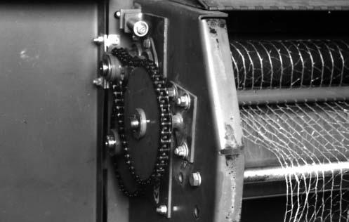
The pressure on the Pinch Drive Roller against the Idler Roller is adjusted by the Compression Spring and Adjusting Bolt on each side. Starting with the Adjusting Bolt loose, set the pressure by equally tightening both Adjusting Bolts just enough to allow rotation of the Idler (Steel) Roller. Equal pressure should be maintained on both sides by measuring the Spring compressed distance. This distance should be maintained at 1-3/4 to 1-7/8″ (44 to 46 mm).
Feeder Belt Tension & Tracking (Figs. 91, 92 & 93)
NOTE: With different wrap materials in different conditions, it may be necessary to increase the distance between the Guides and Roller.
The Wrap Feeder Belts are preadjusted at the factory. Readjustment may be required after break-in has occurred. The Feeder Belts are friction-driven by the Baler (bale forming) Belts. BE SURE that the Baler Belts are tracking correctly. Refer to the Tracking & Alignment section in this chapter for additional information.
The Wrap Feeder Belt tension and tracking may be adjusted by repositioning the Idler Roller (See Item 1, Fig. 91). Loosen the mounting bolt in the ends of the Idler Roller. Using a suitable prying mechanism, tighten the Feeder Belts equally on each side by moving the idler rolled downward and retighten the mounting bolts.
Enough tension MUST be maintained in the Feeder Belts to make the Belts track properly and prevent relative slippage with the Baler (bale forming) Belts.
Operate the Baler and check the Belt tracking with the Tailgate closed and locked. The Feeder Belts should be adjusted to track straight with minimal rubbing on the Guides while following the Baler (bale forming) Belts relatively close. Lowering the right side of the Roller will cause the Belts to travel to the left.
If the Feeder Belts still do NOT track satisfactorily, it will be necessary to adjust the top Feeder Roller (See Item 1, Fig. 93). Start by loosening the idler roller and allow the Belts to go slack on both sides. The top Feeder Belt Roller Shaft should be parallel with the Baler Belt Tracking Roller before making the initial adjustment for Feeder Belt tracking. When doing the tracking adjustment, lowering the right side of the top Feeder Roller will cause the Belt to track to the right. Usually, sliding the top Roller 1/8 to 1/4″ (3 to 6 mm) is an adequate adjustment. Proceed by tightening the Lower Idler Roller as outlined earlier in this section.
Feeder Belt Fingers (Figs. 94 & 95)
The Feeder Belt Fingers are provided to guide the Netting. In their positions next to the Lower Feeder Belt Roller, the Fingers must not contact the sides of the belt. Heating of the guides by belt contact will melt the net as it is pulled towards the bale. Also, in this area, the Fingers strip the Netting from the Feeder Belts. As the Netting is brought along by the (bale forming) Belts, the Fingers guide the Netting toward the bale, in the area of the Tailgate Roller. The Fingers should always be adjusted to and maintained at a distance of 1/4″ (6 mm) away from the Rollers in both positions.
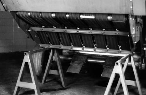

NOTE: BE SURE to check that all of the Fingers are secured on the left side of their respective Mounting Tabs.
Brake (Net) Tension (Figs. 96, 97
& 98)
The Quick Wrap Net tension is established and controlled by the Brake Tension on the right side of the Quick Wrap unit. To properly adjust the Brake and subsequent Net tension, proceed as follows:
NOTE: Brake tension adjustment regulates the amount of Quick Wrap Net tension on the bale. Establishing a measured tension of 130 to 160 in-lb (15 to 18 Nm) on the Rubber Drive Roller, with a torque wrench, will provide the correct amount of Net tension. Too much tension will prevent the Net starting onto the bale. Too little tension will cause the Net to be wrapped too loosely causing poor weathering and crop loss.
1.Fully extend the Actuator.
2.Adjust the Washer assembly on the Strap so the Bushing will catch in the detent, just as the Actuator is fully extended. BE SURE the Bushing is free to rotate on its mounting Bolt (See Item 2, Fig. 97).
3.Using the Set Screw and Jam Nut on the side of the Brake Caliper, adjust the Activation Arm so it is perpendicular to the Caliper Housing (Fig. 97).
4.Adjust the Spring length to 2–1/6″ (52 mm) (Fig. 96).
5.Manually retract the Actuator. As the Actuator is retracted, the Strap assembly should hold the Pivot Assembly still and prevent it from rotating with the Actuator. (This maintains the same Brake tension as when the Actuator is fully extended.)

7.Use a torque wrench to check the torque reading on the Rubber Drive Roller. The torque should be 130-160 in-lb (15 to 18 Nm), when the Brake is fully applied. If the torque is NOT correct, adjust the Spring length to obtain a reading of 130-160 in-lb (15 to 18 Nm), to rotate the Rubber Drive Roller (Fig. 98).
8.Retract the Actuator to make sure that the Strap, catching the Detent, is releasing properly. When the Actuator is approximately 2/3 fully retracted, the Washer (on end of Actuator Rod) should disengage the Strap assembly from the “detent” position and release the Brake.
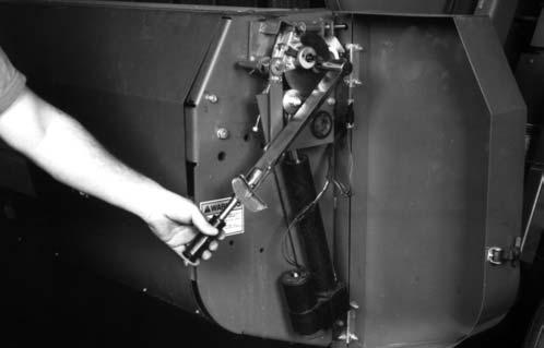

NOTE: Drive Rollers should be able to be rotated by hand when Actuator is retracted.
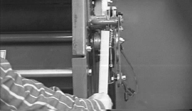
Chapter 8 Lubrication
General Information Warning
NEVER lubricate the machine when any part of the unit is in motion. ALWAYS exercise the MANDATORY SAFETY SHUTDOWN PROCEDURE (page 10), BEFORE lubricating the machine.
It is well to remember that a sufficient amount of oil or grease will prevent excessive part wear and early failure.
IMPORTANT: Whenever service is performed on hydraulic components (valves, cylinders, hoses, etc.) or Transmission, care must be taken to prevent discharging fluid onto the ground. Catch and dispose of fluid per local waste disposal regulations.
Transmission Lubrication
The Transmission should be checked after every 100 hours of operation and the oil level replenished as necessary. The Transmission requires 1 quart (.95 liters) of SAE 80W90 EP Gear Lube.
The Transmission should be checked occasionally for oil drips and dust accumulation which indicates the Seals are leaking. Oil which is tan in color and foams excessively indicates that it has water present and should be replaced.
The Transmission is drained by removing the lower Plug on the Transmission or Dipstick pipe tee. All plugs are located on the right side of the Transmission and are accessed beneath the Baler Cross Frame. Fill Transmission with the proper type and amount of oil or until oil appears at the oil check hole or the proper mark on the Dipstick. Replace all Plugs.
IMPORTANT: Do NOT overfill the Transmission. Only fill it to the bottom of the Inspection Plug hole or to the mark on the Dipstick (for those models with Dipsticks).
Tdc Hydraulics System
Maintain the fluid level in the Sight Tube at NO higher than the upper oil level Decal mark on the Reservoir with the Density Cylinders fully retracted. The TDC system comes primed from the factory with a special grade of hydraulic oil capable of operating at lower ambient temperatures than normal hydraulic oils. If low temperatures and slow shuttle returns are not a problem, ATF (Dexron II) is an acceptable oil to use in the TDC system. During the baling season, the fluid level should be checked before each day of operation (or at least once every 10 hours) and replenished if the fluid drops below the lower oil level decal mark with the Density Cylinders fully retracted.
Oiling
Lubricate all Drive Chains every 10 hours (or daily) of operation using a clean oil or a good grade of foaming aerosol lubricant. The recommended method is to spray the entire length of Chain on the center of the Rollers sufficiently to allow the chain sidebars to be thoroughly lubricated. It is better to lubricate Chains when they are warm (after use, rather than before).
NOTE: For a Baler equipped with an accessory Automatic Chain Oiler, fill the Oil Reservoir Tank as often as necessary with a good grade of clean petroleum oil (SAE 20-40). Usually, a full Tank should provide adequate lubrication for producing 100-150 bales.
Apply oil or foaming aerosol lubricant to the threads of the Pickup Height Adjustment Crank every 100 hours (or monthly).
Apply oil or foaming aerosol lubricant on all Bale Starter Pivot Bushings at the end of each baling season or before storing Baler. Best results are obtained if oil is applied at the end of day or when Bushings are warm.
IMPORTANT: Remove any stems or leaves which might be wrapped around shafts next to Bearings. Wrapped debris buildup can be damaging to the Bearing Seals.
Greasing
NOTE: Grease all fittings on a prescribed basis, at the intervals of operation listed, before and after storing the unit, and as otherwise indicated. Use a good grade of Lithium base grease.
Wipe dirt from the fittings before greasing to prevent the dirt from being forced into the Bearing or Pivot. Replace any missing fittings, when noted. Force the grease into the fitting until it comes out at the Bearing Seal or at the Shaft. To minimize dirt buildup, avoid excessive greasing.
IMPORTANT: In addition to the fittings, inspect and repack the Wheel Bearings at least once a season. The Telescoping PTO Drive should also be separated and grease applied to the splines at least three times during the harvesting season. Apply a light coat of grease on the Twine Knife following each season and before placing the Baler into storage.
Quick Wrap Lubrication
The Drive Roller Chains should be lubricated every 100 hours using a good grade of foaming aerosol lubricant. The recommended method is to spray the entire length of Chain on the center of the Rollers sufficiently to allow the chain sidebars to be thoroughly lubricated.
The only other required lubrication on the Quick Wrap unit is to apply oil or foaming aerosol lubricant to the various hinge or pivot points annually.
Grease Fitting Locations
Grease Every 10 hours (or Daily)
1.Telescoping Drive Crosses (3 Places) (can be either center of Cross or end of Cross)
2.Universal Jackshaft
3.Idler Arm Pivot (Right Side)
4.Lower 8″ Roller Bearing Housing (1 each side)
5.Lower 16″ Roller Bearing Housing (1 each side) (On right side, hidden beneath shield)
6.Packing Roller Arm Bearing (1 each side)
7.Packing Roller Arm Pivot (1 each side)
8.Bale Starter Pivot Bearing (1 each side)
9.Gate End Roller Bearing (1 each side)
10.Gate Latch Torsion Tube Pivot (1 each side)
11.Scraper Roller Bearing Housing (1 each side)
Grease Every 50 hours (or Weekly)
12.Overrunning Clutch (Scraper Roll)
13.Pickup Drive Belt Idler Pivot
14.Twine Tie Pivots (2 Places)
15.Pickup Flotation Torsion Shaft Pivot (1 each side)
16.Telescoping Drive Tube
17.CV Joint Housing (2 Places)
18.Gate Cylinder Pivot (1 each side)
19.Gate Latch Bearing (1 each side)
20.PTO Overrunning Shear Device
Grease Every 100 hours (or Monthly)
21.Gate Pivot Bushing (1 each side)
22.TDC Cylinder Idler Pivot (1 each side)
23.Optional Crowder Wheel Pivot (1 each side)
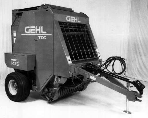

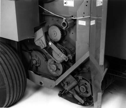

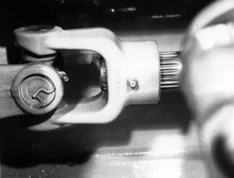

The following is a duplicated listing of the Grease Fitting Locations provided for your convenience when viewing the locations in the photographs.
Grease Fitting Locations
Grease Every 10 hours (or Daily)
1.Telescoping Drive Crosses (3 Places) (can be either center of Cross or end of Cross)
2.Universal Jackshaft
3.Idler Arm Pivot (Right Side)
4.Lower 8″ Roller Bearing Housing (1 each side)
5.Lower 16″ Roller Bearing Housing (1 each side) (On right side, hidden beneath shield)
6.Packing Roller Arm Bearing (1 each side)
7.Packing Roller Arm Pivot (1 each side)
8.Bale Starter Pivot Bearing (1 each side)
9.Gate End Roller Bearing (1 each side)
10.Gate Latch Torsion Tube Pivot (1 each side)
11.Scraper Roller Bearing Housing (1 each side)
Grease Every 50 hours (or Weekly)
12.Overrunning Clutch (Scraper Roll)
13.Pickup Drive Belt Idler Pivot
14.Twine Tie Pivots (2 Places)
15.Pickup Flotation Torsion Shaft Pivot (1 each side)
16.Telescoping Drive Tube
17.CV Joint Housing (2 Places)
18.Gate Cylinder Pivot (1 each side)
19.Gate Latch Bearing (1 each side)
20.PTO Overrunning Shear Device
Grease Every 100 hours (or Monthly)
21.Gate Pivot Bushing (1 each side)
22.TDC Cylinder Idler Pivot (1 each side)
23.Optional Crowder Wheel Pivot (1 each side)
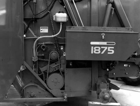
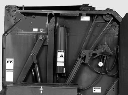


Chapter 9 Service Warning
BEFORE Servicing this unit, exercise the MANDATORY SAFETY SHUTDOWN PROCEDURE (page 10).
NOTE: The following information is referred to in both the Troubleshooting Guide and the Maintenance Schedule chapters of this manual. It should also be understood that all services covered in this chapter are Owner-Operator responsibilities. Where indicated, certain service routines should only be carried out by an authorized GEHL Dealer or GEHL Company representative.
SEALED BALL BEARING REPLACEMENT (Fig. 99)
Sealed Ball Bearings are used on various Shafts around the unit. This type of Bearing is generally retained in place with a Self-locking Eccentric Collar. The Lock Collar has a counter bored recess, which is eccentric with the Collar bore. This eccentric recess engages or mates with an eccentric end of the Bearing inner ring, when the Bearing is assembled on the Shaft. The Bearing is engaged, on the inner ring cam, by the Collar. This assembly grips the Shaft tightly with a positive binding action that increases with use. The Collar Set Screw provides supplementary locking.
A Bearing can be removed from the Shaft by loosening the Set Screw and tapping on a punch which is placed in the drift pin hole, to loosen the Collar. Install Bearings with self-locking Collars in the following manner:
1.Place the Bearing and Collar on the Shaft with the cam surfaces next to each other. Tighten the bolts on the Bearing Retainers.
2.Mate the cam of the Lock Collar with the cam of the Bearing inner ring.
3.Press the Locking Collar against the Bearing wide inner ring and turn it, in the direction of Shaft rotation, until it tightly engages. Tighten the Collar further by tapping on a punch inserted in the drift pin hole.
NOTE: Avoid damaging the Collar by overtightening it.
4.Last, tighten the Set Screw in the Locking Collar.
BALE SIZE INDICATOR CORD (AUTOMATIC & MANUAL TWINE WRAP MODELS ONLY)(Fig. 100)
The Bale Size Indicator Cord links the Pointer above the Indicator Plate to the Belt Shuttle on top of the Baler. Pointer position, through appropriate Cord routing, changes with the position of the Shuttle which moves as the bale grows in size inside the Bale Chamber. If the 3/16″ Cord wears out, a new Cord can be obtained and routed as shown. For the RB1475, order part number 052595 or, for the RB1875, order part number 070607.
Warning
NEVER use your hands to search for hydraulic fluid leaks. Escaping fluid under pressure can be invisible and penetrate your skin causing serious injury! If any fluid is injected into your skin, see a doctor at once! Injected fluid MUST be surgically removed by a doctor familiar with this type of injury or gangrene may result.
PICKUP (Figs. 102, 103 & 104)
1 – Indicator Cord
2 – Pointer
3 – Indicator Plate
Fig. 100: Indicator Cord Routing
GATE HYDRAULICS (Fig. 101)
Refer to the Hydraulic Circuit Diagram provided for details on Gate Cylinder plumbing.
1 – Right Gate Cylinder
2 – Left Gate Cylinder
3 – To Tractor Hydraulics Output
4 – To Optional Chain Oiler
5 – Gate Cylinder Lock Valve
Fig. 101
1 – Three Holes for 3/8 x 3/4″ Cap Screws
2 – Hole for 3/8 x 1-1/4″ Grade 8 Cap Screws
3 – Retainer
4 – Reel
5 – Cam Arm
6 – Cam
7 – Cam Follower (520175)
8 – Cam Bolt (066490)
9 – 1/16″ to 1/8″ (1.6 to 3.2 mm)
Fig. 102: Cam Follower
The Pickup should be inspected on a routine basis every 100 hours of operation. The following inspections should be made:
1.The Cam Follower Bearings should be positioned from 3/16″ to 5/16″ (4.75 to 8 mm) away from the inside edge of the Cam Track as shown.
2.Depending on conditions, the Cam Followers will wear out and need to be replaced. When replacing, it is recommended that the Bolt (GEHL 066490) also be replaced. Apply Loctite 609 or equivalent and torque the Bolt to 75 ft-lb (104 N-m).
NOTE: It is not necessary to remove the Pickup from the Baler to replace the Cam Follower Bearing. An access port is provided. See Fig. 103 for details.
3.To check for Cam wear and binding in the Cam, remove the V-Belt which drives the Pickup and turns the Drive over one complete revolution by hand.
NOTE: Readjust any areas that are binding.
4.Inspect the (4 each side) Sintered-metal Bearings at points where the Bars pivot. Oil Seals are provided on each side of these Bearings. Also, BE SURE to check that the Tine Bar hardware is tightly secured.
5.Check for broken Pickup Tines. Best operation is only obtained after all broken Tines have been replaced. Pickup Tines can be ordered by GEHL number 071607 (for the double Tine) or 071939 (for the single Tine).
The Pickup Drive Sheave has (2) set screw holes and the Driven Sheave has (2) set screw holes. The hole over the keyway contains two set screws, one screw to lock the other, similar to jam nuts. Install the appropriate Sheaves on their respective Shafts as shown.
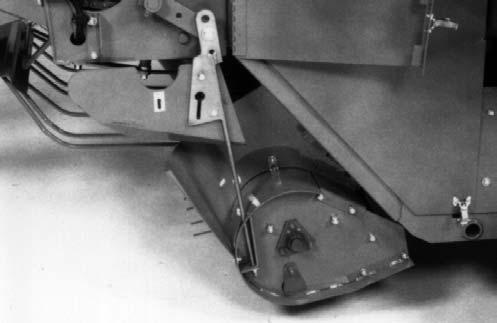
TOTAL DENSITY CONTROL (TDC) SYSTEM WARNING
NEVER use your hands to search for hydraulic fluid leaks. Escaping fluid under pressure can be invisible and penetrate your skin causing serious injury! If any fluid is injected into your skin, see a doctor at once! Injected fluid MUST be surgically removed by a doctor familiar with this type of injury or gangrene may result.
Reservoir Air Pressure (Fig. 105)
The TDC system comes primed from the factory with a special grade of hydraulic oil capable of operating at lower ambient temperatures than normal hydraulic oils. If low temperatures and slow shuttle returns are not a problem, ATF (Dexron II) is an acceptable oil to use in the TDC system. The system is to be pressurized to 150 PSI (1050 kPa) by air pressure in the Reservoir. For normal operation, the Reservoir Pressure Gauge MUST
indicate a pressure reading of 140 to 150 PSI (980-1050 kPa). If the reading is NOT within this range, either add AIR or bleed off AIR, as necessary, using the Tank Inlet and Valve Stem at the top of the Reservoir.
Warning
DO NOT pressurize the Reservoir to more than 150 PSIG (1050 kPa) when adding air and NEVER pressurize with anything other than AIR!
Reservoir (Fig. 105)
The Reservoir fluid level should be checked before each day of Baler operation (or at regular 10 hour intervals) using the Sight Tube located on the forward side of the Reservoir. Proper fluid level can be determined when both Density Cylinders are fully retracted. In this condition, the level of fluid in the Sight Tube should be slightly below the level mark Decal.

NOTE: If the fluid level is below the bottom 1″ (25 mm) level mark, add fluid BEFORE attempting to operate the Baler. Refer to the “Adding Fluid to Reservoir” topic below for proper refilling procedures.
Warning
DO NOT remove any hydraulic lines or fittings until you are sure that the system is depressurized and that there is no load on any hydraulic components. Failure to heed may result in personal injury.
Adding Fluid to Reservoir (Fig. 105)
Warning
NEVER contaminate the reservoir fluid with any flammable liquid. ONLY use non-flammable cleaning solvents for cleaning components or containers used for storing, transporting or transferring the fluid. If the fluid should become contaminated with a flammable liquid, the resulting mixture, when combined with compressed air, can explode causing death or serious injury.
To add fluid to the TDC System Reservoir, proceed as follows:
1.Make sure TDC cylinders are fully retracted (Baler empty and tailgate closed and latched).
NOTE: When operating this machine during times of extreme cold ambient temperatures and if a faster shuttle return speed is desired, use only oil supplied by Gehl in the TDC System. Refer to the “Draining and Repriming System” later in this Chapter for the proper draining procedure.
2.Clean the top of the Reservoir to prevent any contamination during draining or refilling.
3.Fully depressurize the system by loosening or removing (and retaining) the Valve Stem from the Inlet at the top of the Reservoir.
4.Remove and retain the Relief Valve Adapter from the top of the Reservoir.
5.The TDC system comes primed from the factory with a special grade of hydraulic oil capable of operating at lower ambient temperatures than normal hydraulic oils. If low temperatures and slow shuttle returns are not a problem, ATF (Dexron II) is an acceptable oil to use in the TDC system. Add the necessary amount of fluid through the Relief Valve Adapter opening to bring the level in the Sight Tube in line with the lower level mark on the TDC Reservoir (both Density Cylinders MUST be fully retracted when using the lower level mark).
6.After the proper amount of fluid has been added, reinstall and secure Relief Valve Adapter (and Valve Stem, if removed) at top of the Reservoir.
7.Using AIR pressure ONLY, repressurize the system to 140-150 PSI (980-1050 kPa).
If the system has air in it (or gets air into it from opening a hydraulic line), it MUST be reprimed. Or, if the system requires complete draining (to change to a lighter or heavier fluid, for example), refer to the “System Draining and Repriming Procedure” for details.
System Draining and Repriming Procedures (Fig. 105)
1.Make sure TDC cylinders are fully retracted (Baler empty and tailgate closed and latched).
2.Clean the top of the Reservoir to prevent any contamination during draining or refilling.
3.Fully depressurize the system by loosening or removing (and retaining) the Valve Stem from the Inlet at the top of the Reservoir.
4.Remove and retain the Hardware securing the Trip Spacer to the Trip Arm for the right side Density Cylinder and remove the Trip Spacer. This MUST be done to prevent accidental activation of the Valve Trip Mechanism.
5.Fully extend both Density Cylinders by pulling on the Belts at the back of the Baler (this will pull the Shuttles back and extend the Cylinders) and then block them in the extended position so they will NOT retract.
6.Check the fluid level in the Reservoir. With both Density Cylinders fully extended, the fluid level should be in line with or slightly above the upper level mark on the Reservoir. If fluid has to be added, go to Step 9.
If the fluid is going to be drained and replaced, continue with Step 7. If repriming is all that is required, go to Step 9.
7.Place a 2 gallon or larger container near the right side Density Cylinder to catch the fluid during draining. Disconnect the TDC Reservoir Hydraulic Hose at the Manifold Disconnect and allow the fluid to drain into the container.
IMPORTANT: Whenever service is performed on hydraulic components (valves, cylinders, hoses, etc.), care must be taken to prevent discharging fluid onto the ground. Catch and dispose of fluid per local waste disposal regulations.
8.After draining is completed, reconnect the Hydraulic Hose at the Manifold Disconnect.
9.Remove and retain the Relief Valve Adapter from the top of the Reservoir.
10.The TDC system comes primed from the factory with a special grade of hydraulic oil capable of operating at lower ambient temperatures than normal hydraulic oils. If low temperatures and slow shuttle returns are not a problem, ATF (Dexron II) is an acceptable oil to use in the TDC system. Add the necessary amount of fluid through the Relief Valve Adapter opening to bring the level in the Sight Tube in line with the upper level mark on the TDC Reservoir (both Density Cylinders MUST be fully extended when using the upper level mark).
11.After the proper amount of fluid has been added, reinstall and secure Relief Valve Adapter (and Valve Stem, if removed) at top of the Reservoir.
12.Check the Belts to MAKE SURE that they are NOT twisted and remove any blocking used to hold the Density Cylinders in the extended position.
13.Using AIR pressure ONLY, repressurize the system to 140-150 PSI (980-1050 kPa). Repressurizing the Reservoir forces oil through the hydraulic lines and retracts the Density Cylinders.
14.Bleed any air that may have entered the Density Cylinders by carefully opening the Bleed Valve at the top of each Density Cylinder.
NOTE: It may be necessary to repeat steps 3., 9., 10., 11., 12. and 13. several times in order to completely bleed the air from the Density Cylinders.
15.Reinstall the Trip Spacer and secure it to the Trip Arm. MAKE SURE that the Trip Spacer properly contacts the Valve Trip Mechanism before resuming baling.
Pressure Relief Valve (Figs. 105 & 106)
Faulty Valve Operation
Malfunction of the Adjustable Pressure Relief Valve is suspected if one or more of the following conditions arise while baling:
1.If desired density bale can NOT be produced, contamination may be keeping the Relief Valve Poppet from seating properly. To test this: first, fully depressurize the system by loosening or removing (and retaining) the Valve Stem from the Inlet at the top of the Reservoir. Then, remove the Pipe Plug from the top of the Adjustable Relief Valve Manifold and in its place, install a 1000 PSI (7000 kPa) MINIMUM pressure gauge. Next, loosen the Locking Ring on the Adjustable Relief Valve (turn it counterclockwise) and then, gently turn the End Disc clockwise until it bottoms. Now, remove the Trip Spacer and rotate the Valve Trip Mechanism clockwise to its upper stop position. Make sure that there is sufficient fluid in the Reservoir and then open the Gate to extend the Density Cylinders. The indicated pressure on the pressure gauge (installed above) MUST be at least 500 PSI (3500 kPa), otherwise the Relief Valve Poppet is NOT seating properly.
2.If the Density Cylinders will NOT retract quickly, contamination may be blocking the Check Valve and preventing the hydraulic oil from flowing freely through the Valve. To check this, turn the Valve Trip Mechanism to its counterclockwise stop position when the Density Cylinders are extended. If the Cylinders quickly retract, the Check Valve is malfunctioning.
3.If excess power is required for baling or if frequent Belt failure is experienced, contamination may be blocking the Relief Valve Poppet, thereby preventing free flow of fluid through the Valve. To test this, use the same test procedures as for Step 1 above and if the gauge reading rises above 700 PSI (4900kPa), the Relief Valve may be blocked.
If any or all of the above situations occur, the Pressure Relief Valve can be partially disassembled following details in the next topic.
Relief Valve Removal & Replacement
If the Adjustable Pressure Relief Valve is suspected of leaking or blockage, it can be partially disassembled in the following manner:
Warning
DO NOT remove any hydraulic lines, fittings or components until you are sure that the system is depressurized and that there is no load on any hydraulic components. Failure to heed may result in personal injury. To fully depressurize the system, loosen or remove (and retain) the valve stem from the inlet at the top of the reservoir (see Ref. 2, Fig. 108).
1.MAKE SURE the system is depressurized. Also, MAKE SURE the Density Cylinders are fully retracted and there is NO bale in the machine.
2.Carefully disconnect the Reservoir-to-Manifold Hose at the Manifold Disconnect Coupler.
3.Remove and retain all but one of the four Manifold Bracket mounting bolts so the Manifold assembly can be swung clockwise as far as the Hose connections will allow and temporarily secured (with the remaining screw). The Manifold should be rotated to avoid excessive fluid loss.
IMPORTANT: Whenever service is performed on hydraulic components (valves, cylinders, hoses, etc.), care must be taken to prevent discharging fluid onto the ground. Catch and dispose of fluid per local waste disposal regulations.
Warning
BE SURE to wear a face and eye protection shield or goggles and position yourself so that your face is away from the valve to prevent contact with the escaping fluid.
4.Carefully loosen the Adjustable Relief Valve and bleed off pressure from the system.
5.After pressure has been removed, the Valve can be removed from the Manifold and the opening should be plugged to prevent contamination.
6.Inspect the Cartridge for a leaky or blocked Poppet. Force the Poppet on the front end of the Cartridge backward and, using a clean punch, rotate the Poppet to dislodge any contamination.
7.After step 5 has been performed, check the two outside O-rings for damage and then replace the Cartridge into the Manifold.
8.With the Cartridge replaced, reattach the Manifold assembly into its original mounting position and secure it.
9.Carefully and properly reconnect Quick coupler.
10.Check the Reservoir fluid level and pressurize to 140-150 PSIG (980-1050 kPa) before attempting to resume operation.
NOTE: If the Baler fails to operate properly after the above procedures have been carried out, contact your dealer for further directives. To order replacement Valve Cartridge, specify GEHL part #094191 (1475) and 127112 (1875).
To repair Cartridge specify GEHL part #094193 for Seal Kit. Replace Check Valve with part #119302.
Transmission
IMPORTANT: Internal Transmission component repairs and replacements should only be attempted by (or under the direction of) an authorized GEHL equipment dealer.
To remove Transmission for service, proceed as follows:
1.Remove Windguard Assembly.
2.Remove Twine Tie System (5 bolts, 1 electrical connection on Manual Tie, 2 electrical connections on Auto-Electric models).
3.Release Drive Chain tension, break the Drive Chain and loosen the Bearing attaching hardware.
4.Loosen 4 flangette mounting bolts on cross shaft.
5.Slide cross shaft off of transmission output shaft.
6.Remove the (4) fasteners securing the Transmission Housing to the Crosstube.
7.Carefully remove the Transmission from the unit. After service is performed, replace the Transmission in reverse order of removal. Then, replace the oil until it comes out the Inspection Hole or reaches the full mark on the Dipstick. The Transmission requires 3 U.S. pints of SAE 80W90EP Gear Lube. Replace and readjust the Drive Chain.
Twine Knife
When resharpening the Twine Knife, only sharpen the beveled edge. Remove the (2) bolts to take the Knife off the Cut-off Arm.
Belts Warning
BEFORE Servicing this unit, exercise the MANDATORY SAFETY SHUTDOWN PROCEDURE (page 10).
Activating Shuttle Locks (Fig. 107)
Warning
BEFORE servicing the belts, BE SURE to release the tension on the belts with the shuttle locks. NEVER have the PTO engaged while the shuttle locks are engaged. ALWAYS engage BOTH locks to make sure that belt tension is completely locked out.

To use the Shuttle Locks, first open the Gate. Then, carefully climb up onto Twineboxes, remove the
Hairpin Cotterpins and swing the Locks over. Reinstall the Hairpin Cotterpins, carefully climb down and then slowly close the Gate.
Belt Tension (Fig. 108)
If the Belts do NOT return or otherwise are NOT returning fast enough after ejecting a bale, check out the following items in the order listed to troubleshoot and correct the problem.
1.Check the Gauge pressure for the Reservoir while the Baler is empty. If the pressure reads less than 140-150 PSI (980-1050 kPa), add air to bring the pressure up to 140-150 PSI (980-1050 kPa). If the pressure drops again after a short time, there is most likely a leak at one of the fitting connections. To find the leak, apply a soapy water solution to the fittings and watch for air bubbles to form. As necessary, tighten the fitting connection or replace the fitting. Be careful NOT to overtighten the fittings and damage the threads.
2.Check the Reservoir hydraulic fluid level. With the Cylinders fully retracted, the fluid should be between 1″ (25 mm) from the bottom of the Reservoir to just below the Oil Level Decal mark. Refer to TDC System topic in this chapter under Reservoir subtopic for additional information.
3.Check the plumbing arrangement and compare your machine to the routing shown in the TDC Hydraulic Circuit Diagram provided.
4.Check the operation of the Pressure Relief Valve following details under the Pressure Relief Valve subtopic contained within the TDC System information in this chapter.
5.Check for sticking Density Cylinders. Release the Reservoir air pressure. Remove the Trip Spacer from the Trip Arm and then fully extend both Density Cylinders by pulling the Belts at the back of the Baler. Slowly pressurize the Reservoir to 25 PSI (75 kPa). Cylinders should retract completely and smoothly.
Cause of Belt Failure
When a Belt fails, it will usually occur in the area of Lacing Hooks and will be caused by one or more of the following:
1.Bale improperly formed.
2.Lacing wire worn or broken.
3.Belt not properly laced.
4.Belts not tracking properly.
5.Build-up on Roller(s) or Scraper.
6.Baling when conditions are too wet.
Splicing and Re–lacing (Fig. 109)
Belts are laced with #4-1/2HT Clipper Lacing Hooks and 3/32″ diameter Nylon-coated Cable. These materials and a 6″ (152 mm) Vice Lacer can be obtained as service accessories; see the Optional Features & Accessories chapter of this manual.
To relace a Belt, the following additional items will be needed: small square, ball–point pen, sharp knife, long-nose pliers, slip-joint pliers and a vice.
To re–lace a Belt, follow the procedure below:
1.Open the Rear Gate, engage the Shuttle Locks and completely close Gate to remove Belt tension. Then remove the Belt to be re–laced.
2.Mark the Belt with the small square and ball–point pen just behind the old hooks or 5/8″ (16 mm) from the end of the Belt. Carefully cut the Belt with a sharp knife. Check the squareness from both sides after cutting. Clip the corners as shown.
NOTE: Relace both ends of a pulled lacing joint. By limiting the amount of Belt cut to 5/8″ (16 mm) on each end, a Belt can be re–laced twice before alternative action is required; see Maintaining Belt Length section for details.
3.Install #4-1/2HT Hooks with the Vice Lacer. Make sure the ends of the Hooks protrude through the Belt and are clinched over.
4.Make sure outside Hooks are on the leading Belt end. Install relaced Belt in the Baler.
5.Cut an 8″ (203 mm) long piece of Nylon-coated Cable. Bend a 3/4″ (19 mm) loop in one end of the Cable. Install Cable in splice positioning loop as shown.
6.Restore Belt tension by opening the Rear Gate and returning the Shuttle Locks to storage.
7.Using the long-nose pliers, trim and bend the remaining end of the Cable into a loop with a minimum of 3/4″ (19 mm) engagement into the lacing.
NOTE: To keep the belt splice in good operating condition, it is recommended that the Lacing Cables be replaced every 500 bales.
1
4
Maintaining Belt Length
The length of the Belts should be maintained within 2-1/2″ (63.5 mm). This 2-1/2″ (63.5 mm) difference between Belt lengths can be achieved in either of two ways: a.by switching Belts around to different positions, or b.by using Dutchman Splices.
a) Switching Belts
The lacing on the outside Belts is more likely to fail before the inside Belt lacing. Outside Belts that have already been relaced can be switched towards the center of the Baler where less stress will be placed on the lacing.
NOTE: This practice of switching is the recommended procedure for purposes of expense and repair time reduction.
b) Dutchman Splice
The original or matching Belt length can be restored by using a Dutchman Splice on a Belt which has been shortened excessively by repeated re–lacings, a diagonal cut or a tear.
NOTE: It is important to keep an accurate record of re–lacing for each Belt so that a Belt can be re–laced twice before the Belt is switched or a Dutchman is necessary.
Dutchman Splice Installation
NOTE: The Dutchman Splice MUST be at least 12″ (305 mm) in Belt length for ample lacing separation. If Lacings are staged too close together, the Belt Lacings will fail quicker. BE SURE to use the longest Dutchman available as the piece that will be cut off. The long Belt will (hopefully) be good enough for more than 1 foot and then itself be usable as a Dutchman. Refer to the Optional Features & Accessories chapter for Dutchmans available.
RB1475 Belt (Fig. 110)
Perform the following steps to restore a short or torn RB1475 Belt:
1.Cut one end off the long Belt as close to the damaged area as possible and without including the damaged area. Relace this end.
2.Determine what overall length of Belt has to be developed (Belt length only, NOT including Lacing). To determine the overall length, consider the following: a.A new Belt is 469″ (11 913 mm) long. b.Belts should be maintained within 2-1/2″ (63.5 mm) of each other. c.Check your records as the Belt may already have been reduced in length due to previous Lacing failures.
3.After the overall length required has been determined, subtract the following: a.Dutchman belt length b.Extra gap necessary of 1/2″ (13 mm)
4.After the above measurements and calculations are made, cut the long Belt to the appropriate length determined and re–lace it.
5.Install the Cable Lacing Pin in one joint, reassemble the Belt into the Baler and install the other Cable Lacing Pin.
Example
Given a 36″ (915 mm) Dutchman and a full length Belt that is badly torn and now needs to be re–laced. To what length should the damaged Belt be cut. Refer to Fig. 110 and follow the calculation below.
Solution
Belt Length Desired? (This may be less than 469″ if all other Belts have already been cut off)469″
Minus Dutchman Belt Length-36″
Minus Additional Belt Gap-1/2″ (Due to additional Lacing)432-1/2″
Therefore, Belt MUST be cut to a length of 432-1/2″
1.Cut one end off of the long Belt as close to the damaged area as possible and without including the damaged area. Re–lace this end.
2.Determine what overall length of Belt has to be developed (Belt length only, NOT including Lacing). To determine the overall length, consider the following: a.A new Belt is 552″ (14 021 mm) long. b.Belts should be maintained within 2-1/2″ (63.5 mm) of each other. c.Check your records as the Belt may already have been reduced in length due to previous Lacing failures.
3.After the overall length required has been determined, subtract the following: a.Dutchman belt length b.Extra gap necessary of 1/2″ (13 mm)
4.After the above measurements and calculations are made, cut the long Belt to the appropriate length determined and re–lace it.
5.Install the Cable Lacing Pin in one joint, reassemble the Belt into the Baler and install the other Cable Lacing Pin.
A + B + 1/2″ (13 mm) = Belt Length Desired 1 – 469″ (11 913 mm) 2 – New Belt 3 – Belt Length Desired 4 – Tear 5 – 1/2″ (13 mm) 6 – 3/8″ (9.5 mm) 7 – 35-1/4″ (895 mm)
8 – 1/4″ (6 mm)
9 – 432-1/2″ (10 986 mm)
Fig. 110: RB1475 Belt Repair Detail
RB1875 Belt (Fig. 111)
Perform the following steps to restore a short or torn RB1875 Belt:
Example
Given a 36″ (915 mm) Dutchman and a full length Belt which is badly torn and now needs to be relaced. To what length should the damaged Belt be cut. Refer to Fig. 111 and follow the calculation below.
Solution
Belt Length Desired? (This may be less than 552″ if all other Belts have already been cut off)552″
Minus Dutchman Belt Length?-36″
Minus Additional Belt Gap?-1/2″ (Due to additional Lacing)515-1/2″ Therefore, Belt MUST be cut to a length of 515-1/2″
A + B + 1/2″ (13 mm)
1 – 545-1/4″ (14 021 mm)
2 – New Belt
3 – Belt Length Desired
4 – Tear
5 – 1/2″ (13 mm)
6 – 3/8″ (9.5 mm)
7 – 35-1/4″ (895 mm)
8 – 1/4″ (6 mm)
9 – 515-1/2″ (14 021 mm)
= Belt Length Desired
Check the Baler Tire pressure after every 50 hours of operation. Tires should be inflated to the 40 PSI (280 kPa). Wheel Lug Nut torque should be checked after every 50 hours of operation and tightened to 90 ft-lb (124 Nm) torque.
Warning
Inflating or servicing tires can be dangerous. Whenever possible, trained personnel should be called to service and/or mount tires. In addition, DO NOT place your fingers on the tire bead or rim during inflation; serious injury or amputation could result. In any event, to avoid possible death or serious injury, follow the safety precautions below:
• BE SURE the rim is clean and free of rust.
• Lubricate both the tire beads and rim flanges with a soap solution. DO NOT use oil or grease.
Fig. 111: RB1875 Belt Repair Detail
WHEELS & TIRES
NOTE: Our Company does NOT sell replacement Tires. In addition, Tire mounting, repair and replacements should ONLY be attempted by a qualified tire manufacturer’s representative or by properly trained personnel following the tire manufacturer’s instructions. If you do not have such instructions, contact your tire dealer or our Company.
• Use a clip-on tire chuck with a remote hose and gauge, which allows you to stand clear of the tire while inflating it.
• NEVER inflate beyond 35 PSI (240 kPa) to seat the beads. If the beads have not seated by the time the pressure reaches 35 PSI, deflate the assembly, reposition the tire on the rim, relubricate both parts and reinflate it. Inflation pressure beyond 35 PSI with unseated beads may break the bead or rim with explosive force sufficient to cause death or serious injury.
• After seating the beads, adjust the inflation pressure to the recommended operating pressure listed.
• DO NOT weld, braze, or otherwise attempt to repair and use a damaged rim.
Quick Wrap Service
Knife Removal and Installation (Figs. 112 & 113)
1.Begin by fully extending the Electric Actuator to rotate the Knife Holder away from the Knife Cutoff position. Then, unplug the Actuator to guarantee that the Knife can NOT be accidentally rotated.
Warning
Knives are very sharp.
4.Take special notice of the position of the Knives and Knife edges.
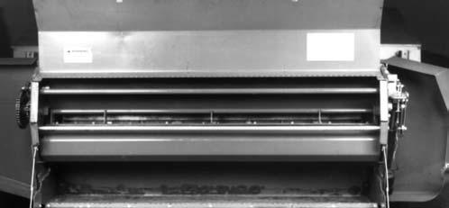

5.Detach the bolts and nuts and remove the Knives from the Knife Holder.
6.Sharpen or replace the Knives.
7.Reinstall the Knives on top of the Knife Holder with the beveled cutting edge facing down.
8.Reinstall the Knife Shield and tightly secure the attaching hardware before resuming operation.
2.Remove the Knife Shield by detaching the (4) mounting fasteners.
3.Rotate the Knife Holder rearward for access to the mounting hardware.