11 minute read
CHAPTER 4 SAFETY


The above Safety Alert Symbol means ATTENTION! BECOME ALERT! YOUR SAFETY IS INVOLVED! It stresses an attitude of ‘‘Heads Up for Safety’’ and can be found throughout this Operator’s Manual and on the machine itself.
BEFORE YOU ATTEMPT TO OPERATE THIS EQUIPMENT, READ AND STUDY THE FOLLOWING SAFETY INFORMATION. IN ADDITION, MAKE SURE THAT EVERY INDIVIDUAL WHO OPERATES OR WORKS WITH THIS EQUIPMENT, WHETHER FAMILY MEMBER OR EMPLOYEE, IS FAMILIAR WITH THESE SAFETY PRECAUTIONS.
Our Company ALWAYS takes the operator and his/her safety into consideration when designing its machinery and guards exposed moving parts for his/her protection. However, some areas can not be guarded or shielded in order to assure proper operation. This Operator’s Manual, and decals on the machine, warn of additional hazards and should be read and observed closely.
Danger
‘‘DANGER’’ indicates an imminently hazardous situation which, if not avoided, will result in death or serious injury.
Warning
‘‘WARNING’’ indicates a potentially hazardous situation which, if not avoided, could result in death or serious injury.
Caution
‘‘CAUTION’’ indicates a potentially hazardous situation which, if not avoided, may result in minor or moderate injury. It may also alert against unsafe practices.
Mandatory Safety Shutdown Procedure
BEFORE unclogging, cleaning, adjusting, lubricating or servicing the unit:
1.Disengage the tractor PTO.
2.Shut off the tractor engine, place the tractor transmission in park and/or lock brake pedals to prevent any tractor movement.
3.On Auto-Electric control equipped balers, BEFORE leaving the tractor seat to perform any function or maintenance, push “POWER” keypad to turn off power to the control.
4.Remove the starter switch key and take it with you when leaving the tractor seat.
5.Wait for all movement to stop.
6.Remove the telescoping drive and ALL power connections from the tractor.
ONLY when you have taken these precautions can you be sure it is safe to proceed. Failure to follow the above procedure could lead to death or serious bodily injury.
Additional Safety Reminders
Some photographs, used in this manual, may show doors, guards or shields open or removed for illustration purposes ONLY! BE SURE that all doors, guards and shields are in their proper positions and securely attached BEFORE operating this unit!
ALWAYS wear safety glasses with side shields when striking metal against metal! In addition, it is recommended that a softer (non-chipable) material be used to cushion the blow. Failure to heed could result in serious injury to the eyes or other parts of the body!
NEVER use your hands to search for hydraulic fluid leaks; use a piece of cardboard. Escaping fluid under pressure can be invisible and penetrate the skin causing serious injury! If any fluid is injected into your skin, see a doctor at once! Injected fluid MUST BE surgically removed by a doctor familiar with this type of injury or gangrene may result.
ALWAYS follow state and local regulations regarding use of a safety chain and transport lighting when towing farm equipment on public highways! A safety chain should always be used to retain the connection between the towing and towed machines, in the event of separation of the primary attaching system! BE SURE to check with local law enforcement agencies for your own particular regulations. Unless otherwise prohibited, use a Slow–moving Vehicle (SMV) emblem. Only a safety chain (NOT an elastic or nylon/plastic tow strap) should be used to retain the connection between the towing and towed machines, in the event of separation of the primary attaching system. Refer to the Optional Features & Accessories chapter for safety chain.
Good safety practice dictates that you NEVER tow an implement that does not have brakes, unless the towing vehicle weighs at least one-and-one half (1-1/2) times the weight of the towed implement and its load. For any public highway travel and to be in compliance with this rule, BE SURE that your tractor is heavy enough to counterbalance the weight of the baler and a full-sized bale.
Limit towing speed to 20 mph (32 km/h).
Always use adequate lights or safety warnings when transporting the machine on public roads and after dark. Check with the local law enforcement agencies for specific requirements.
BE SURE that the telescoping PTO drive rotates freely inside the drive shield tubes at all times. Balers are provided with two different types of telescoping drives; one drive has metal shield tubes and the other has plastic shield tubes. The drive with plastic shield tubes must be anchored to a hole in a part of the baler frame with the tie-down chain provided. The drive with metal shield tubes MUST NOT be anchored.
Bales made with the Round Baler are LARGE, CYLINDRICAL and HEAVY. Serious personal injury or property damage could result if the bales are not carefully and properly handled. NEVER eject or store bales where they could possibly roll downhill.
To ensure continued safe operation, replace damaged or worn-out parts with genuine GEHL service parts, BEFORE attempting to operate this equipment.
Our Company does NOT sell replacement tires. In addition, tire mounting, service or inflation can be dangerous. Whenever possible, trained personnel should be called to service and/or mount tires, following the tire manufacturer’s instructions. If you do not have such instructions, contact your tire dealer or our Company. In any event, to avoid possible fatal or serious injury, follow the specific directives given in the Service chapter of this manual.
BE SURE to review and comply with ALL safety recommendations set forth in the tractor operator’s manual.
REMEMBER, it is the owner’s responsibility for communicating information on the safe use and proper maintenance of this machine.


CHAPTER 5 CONTROLS & SAFETY EQUIPMENT
Each variable chamber Round Baler is provided with several similar features for operator safety and convenience.
Caution
Become familiar with and know how to use ALL safety devices and controls on this machine BEFORE attempting to operate the unit. Know how to STOP machine operation BEFORE starting it.
The Front Guard assembly serves as a barrier and a reminder to KEEP AWAY from the front of the Baler, while it is running. Furthermore, do NOT attempt to place an arm or leg between the Front Guard Bars,while the Baler is operating. The Front Guard assembly can be unbolted at the bottom and pivoted out of the way when necessary. BE SURE the Front Guard assembly is restored to its original position and secured BEFORE resuming operation.
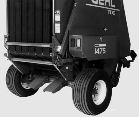
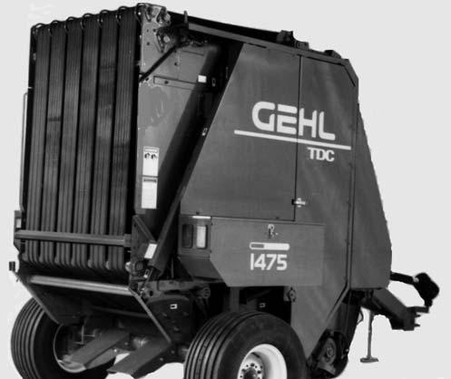
FENDER/TWINEBOX ASSEMBLIES (Figs. 2 & 3)
Warning
NEVER attempt to step up on, stand on or ride on the twineboxes, or any other part of the baler, while the baler is moving or being operated.
Warning
NEVER remove the front guard assembly from the Baler. NEVER stand on or place your arms or legs through the front guard bars while the baler is running or moving. ALWAYS exercise the MANDATORY SAFETY SHUTDOWN PROCEDURE (page 10), BEFORE approaching the front guard assembly.
The Fender/Twinebox Assemblies provide protection for the Tires, a place to store twine, a place to store the Operator’s Manual on the right side, and a place to stand on to engage or disengage the Shuttle Locks.
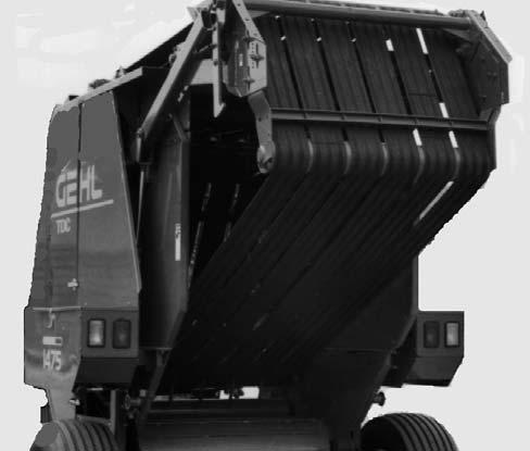
Gate Cylinder Lockout Valve Warning
ALWAYS place the gate cylinder lockout valve in the locked position BEFORE working inside the bale chamber or under the gate when the gate is open.

After SN24715-1475 and SN17900-1875 (Figs. 3, 4 & 5)
The Baler is equipped with a Gate Cylinder Lockout Valve that is used to lock and hold both Gate Lift Cylinders inoperable in any position. The Lift Cylinders are locked in position when the Gate Cylinder Lockout Valve Handle is turned to the vertical position (Fig. 5). The Lift Cylinders are free to operate when the Valve Handle is turned to the horizontal position (Fig. 4).
Before SN24716-1475 and SN17901-1875 (Figs. 3, 6 & 7)
The Baler is equipped with a Gate Cylinder Lockout Valve that is used to lock and hold both Gate Lift Cylinders inoperable in any position. The Lift Cylinders are locked in position when the Gate Cylinder Lockout Valve Handle is depressed into the valve body and the position Indicator is in the vertical position (Fig. 7). The Lift Cylinders are free to operate when the Valve Handle is pulled out from the valve body and the position Indicator is pointing to the Baler and is in the notch (Fig. 6).
1 – Gate Cylinder Lockout Valve in “Open” Position
2 – Indicator in Notch
3 – Tailgate Lock Decal
4 – Red Reflector
SHUTTLE LOCKS (Fig. 8)
Shuttle Locks are provided on both sides of the Baler to remove Belt tension while cleaning or servicing the Baler. Engage both Locks when replacing or re-lacing the Belts and when removing build-up from around the Rollers. Step up on the left or right Twinebox in order to reach the Shuttle Locks.
Warning
NEVER have the PTO engaged while the shuttle locks are engaged. ALWAYS engage both shuttle locks to make sure that belt tension is completely locked out.
Fire Extinguisher Warning
If a fire occurs eject the bale from the baler IMMEDIATELY, move the baler up-wind 30 feet (10 m) or more away from the ejected bale, shut off the tractor engine and proceed to put out the fire with a fire extinguisher.
There is always the possibility of fire when handling dry forage materials. GEHL Company recommends that to limit the damage to the Baler and/or tractor in case of a bale fire, a five gallon or larger, pressurized water type, fire extinguisher should be mounted on the tractor or Baler, as a minimum protection.

NOTE: A five gallon extinguisher should be sufficient to put out small fires that are burning the dry material that remains in the Baler, after the bale is ejected. However, this size extinguisher is insufficient to put out even a small fire in the bale.
Warning
The pressurized water fire extinguisher DOES NOT replace the dry chemical fire extinguisher on the tractor (if so equipped). NEVER use a water–type fire extinguisher on electrical or fuel fires. Furthermore, to reduce the possibility of a fire, keep crop build-up to a minimum, especially on the roller ends, the chain drives (behind the hinged shields) and in the pickup drive area.
GUARDS, DOORS & SHIELDS
Whenever possible and without affecting machine operation, Guards, Shields and/or hinged Covers have been used on this equipment to protect potentially hazardous areas. In many places, Decals are also provided to warn of potential dangers as well as display special operating procedures.
Warning
Read and observe ALL Warnings on the unit BEFORE operating it. Do NOT attempt to operate this equipment unless ALL factory installed Guards and Shields are properly secured in place. BEFORE proceeding to perform any work on the Baler and, BEFORE removing or opening any Shields, BE SURE to exercise the MANDATORY SAFETY SHUTDOWN PROCEDURE (page 10). Also, BE SURE to reinstall and/or close ALL Shields BEFORE operating the Baler.
Front Belt Guard (Fig. 9)
The Front Belt Guard is provided to shield the area of Belt travel around the Drive Roller and Idler Roller. BE SURE the Guard is properly positioned and secured before operating the Baler.
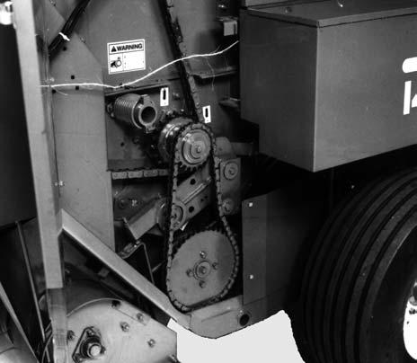
Large Hinged Guard Doors & Removable Side Shields (Fig. 10)
Large Hinged Doors and Removable (hinged with Latch on later models) Side Shields are provided on both sides of the Baler to cover and protect drives and adjustable portion of the TDC system. The Side Shields should be installed (latched on later models) and the doors should be closed and latched whenever the Baler is running.
Warning
When working inside the guard doors or side shields, BE SURE to exercise the MANDATORY SAFETY SHUTDOWN PROCEDURE (page 10).
Pickup V-Belt Guard (Fig. 11)
The pinch point of the Pickup Drive Belt is shielded with a Guard. BE SURE that the Guard is always securely fastened in place while operating the Baler.

HITCHJACK (Fig. 12)
A Hitchjack is furnished with the Baler to support the machine when the tractor is disconnected as well as facilitate aligning the Hitch Clevis with the tractor drawbar for hookup.
When the Jack is NOT being used to support the Baler and to prevent it from being damaged by the tractor tire, it can be removed and relocated to a “Storage” position on the inside of the Drawbar on the left side. Wrap the Chain around the Jack Handle, before inserting the Locking Pin through the Hub holes, to prevent the Handle from dragging on the ground.
Warning
BE SURE the locking pin is entirely and properly inserted through both hub holes on the jackstand BEFORE disconnecting the baler from the tractor.
REVERSING WRENCH (Figs. 13 & 14)
The Round Baler is provided with a Reversing Wrench Handle for manually rotating the Transmission Output Shaft. When NOT in use, the Wrench should be in a stored position located underneath the left Hinged Guard Door (Fig. 14).
Warning
ALWAYS exercise the MANDATORY SAFETY SHUTDOWN PROCEDURE (page 10) BEFORE using the reversing wrench. Also, BE SURE to replace the wrench in its storage location BEFORE resuming baler operation.


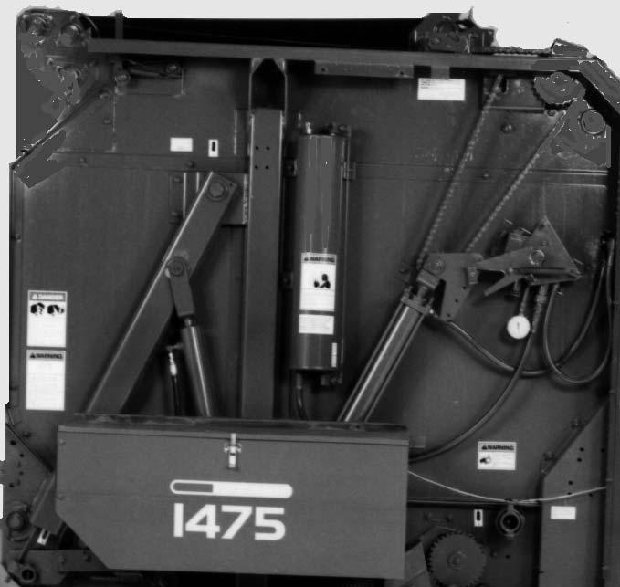
TDC PRESSURE RELIEF (Fig. 15)
A Pressure Relief Valve is provided on top of the TDC Reservoir to automatically release excessive (beyond 300 PSI or 2100 kPa) pressure build-up. The Relief Valve helps to prevent TDC system component damage. The Relief Valve is covered with a protective plastic cap that should remain in place at all times.
AUTOMATIC BALE CONTROL SYSTEM (OPTIONAL) (Fig. 16)
The Automatic Bale Control System model Baler comes equipped from the factory with the Automatic Bale Control System factory installed. The system provides an information center and Baler control for the operator from the tractor. If the Baler is equipped with the Quick Wrap option, the operator may also change from twine tying to a netting wrap without having to leave the tractor.

AUTOMATIC TWINE WRAP SYSTEM (Fig. 17)
The Automatic Twine Wrap model Baler comes equipped with the Auto Twine Wrap Control System dealer installed. The system provides for automated twine wrapping of the bale and as an information center during the baling operation. Bales may also be wrapped in a manual mode. This system is NOT for use on Balers that are equipped with a Net Wrap system.
1
1 – Twine Arm Positioning Switch
Fig. 18: Manual Twine Control Box

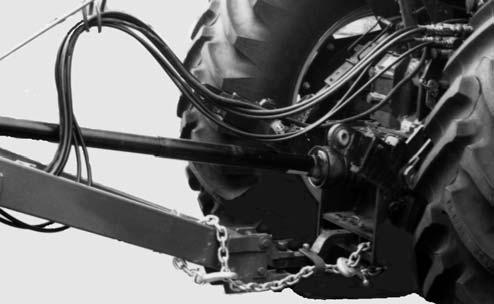
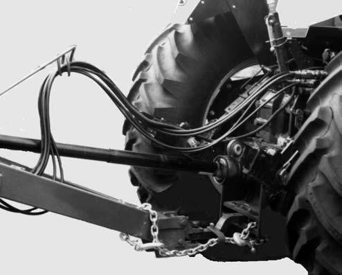
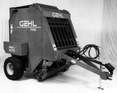
SAFETY CHAIN & TRANSPORT LIGHTING
(Figs. 19 & 20)
Caution
MANUAL TWINE WRAP SYSTEM (Fig. 18)
The manual tie model Baler comes with a Manual Twine Wrap system that is dealer installed. A Baler so equipped will allow manual control of the twine tying cycle from the tractor.
ALWAYS follow state and local regulations regarding a safety chain and transport lighting when towing farm equipment on a public highway! BE SURE to check with local law enforcement agencies for your own particular regulations. Unless otherwise prohibited, use a Slow-Moving Vehicle (SMV) emblem. Only a safety chain (NOT an elastic or nylon/plastic tow strap) should be used to retain the connection between the towing and towed machine, in the event of separation of the primary attaching system.
As required or when desired, the Baler should be equipped with the optional safety chain for transporting the unit on public highways. The chain should be routed as shown in Fig. 19. The Balers are equipped with Transport Lights, which are standard equipment.
TELESCOPING PTO DRIVE (Figs. 19
The Telescoping PTO Drive is designed to rotate freely inside the Drive Shield Tubes.

NOTE: ALWAYS orient and attach the PTO Drive with the CV end coupled to the tractor PTO shaft.

The Telescoping PTO Drive is provided with a Springloaded Locking Device on each end to positively lock the Drive connections onto the tractor PTO shaft and the Baler Drive Input Shaft. Depress the Locking Device, against the Spring tension, and slide the Yoke onto its respective Drive Shaft. Release the Locking Device and move the Yoke ahead or back until the Lock engages into the groove of its respective Shaft.
Warning
BE SURE that the telescoping drive rotates freely inside the drive shield tubes at all times. BE SURE the telescoping drive connections are properly secured to the tractor PTO shaft and baler drive input shaft BEFORE starting the tractor engine. Also, BE SURE the tractor master shield is in place and properly secured BEFORE starting the tractor.
NOTE: For your convenience when the Baler is disconnected from the tractor, the PTO can be placed onto the CV Stand, mounted on the right side of the Hitch Clevis assembly. The CV Stand is designed to be pivoted out of the way when NOT in use. In addition, when transporting the Baler, leave the Telescoping PTO Drive attached to the tractor. If the PTO is NOT connected, it should be disconnected from the Baler and stored in or on the towing vehicle.