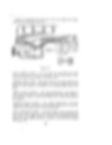
Figure 62 illustrates the fuel flow from the engine fuel supply tank to the combustion chambers.
t
-t
t
t
- 2NO STAGE FILTER-
~...,...,..,
',,,
RELIEF VALVE
SUCTION c:==::1 lOW PRESSURE 1!1111111111111 HIGH PRESSURE ~ llETU II N il[Jl[][]ll
Figure 62 FUEL SUPPLY TANK - An air vent fuel tank filler cap vents air into the tank as fuel is removed. A water trap with a drain valve is located on the bottom of the fuel tank. PRIMER HAND PUMP - The hand primer is located between the fuel tank and the first stage filter. It is used to supply fuel to the filters if the system is worked on or if the tractor runs out of fuel. FIRST STAGE FILTER - The first stage filter is the replaceable type. It removes abrasive particles from the fuel. There is an air bleed screw on top of the filter and a water drain plug on the bottom. SECOND STAGE FILTER - The second stage filter is also the replaceable type. It removes the very fine particles from the fuel. There is an air bleed screw on top of the filter. FUEL INJECTION PUMP - The fuel injection pump receives fuel from the second stage filter and then meters and distributes the fuel under very high pressure to each of the injectors. Fuel in excess of the engine demand is returned to the fuel tank through the return line.
73


