4 minute read
Cooling Sy!!Jtem


TRANSMISSION AND CONVERTER OIL AND FILTER CHANGE
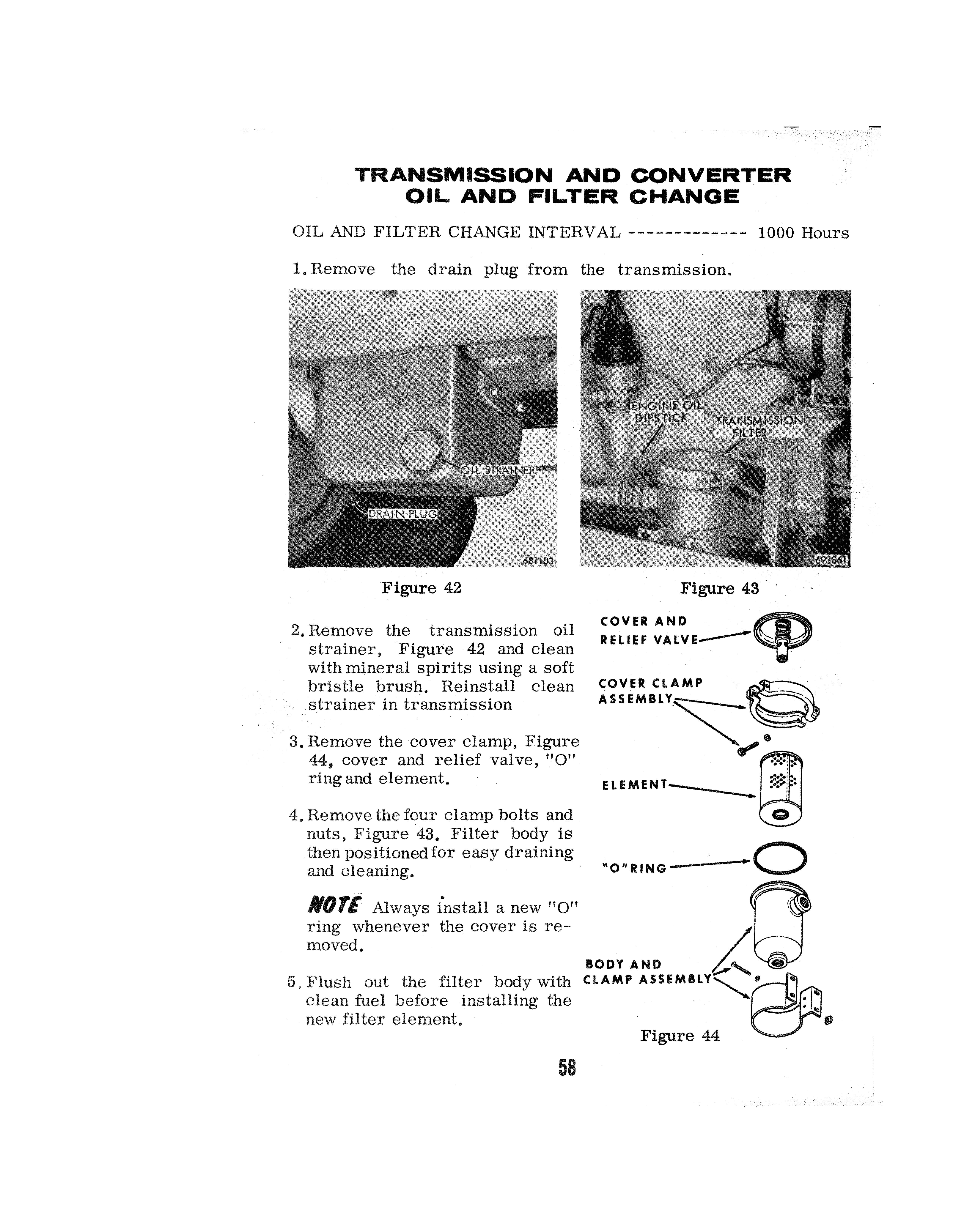
1. Remove the drain plug from the transmission.
Figure 42
2. Remove the transmission oil strainer, Figure 42 and clean with mineral spirits using a soft bristle brush. Reinstall clean strainer in transmission Figure 43 ·
COVER AND t'n RELIEF VALVE----'T'
COVER CLAMP
3. Remove the cover clamp, Figure 44, cover and relief valve, "O" ring and element.
4. Remove the four clamp bolts and nuts, Figure 43. Filter body is . then positioned for easy draining and cleaning.
NOT/ Always install a new "O" ring whenever the cover is removed.
"O"RING----0 g BODY AND . '-., 5. Flush out the filter body with CLAMP clean fuel before installing the new filter element.
Figure 44
58
6. Install new element, •to11 ·ring, cover with relief valve and cover clamp. Tighten cover clamp and position the body on the mounting bolts. Check for oil leaks.
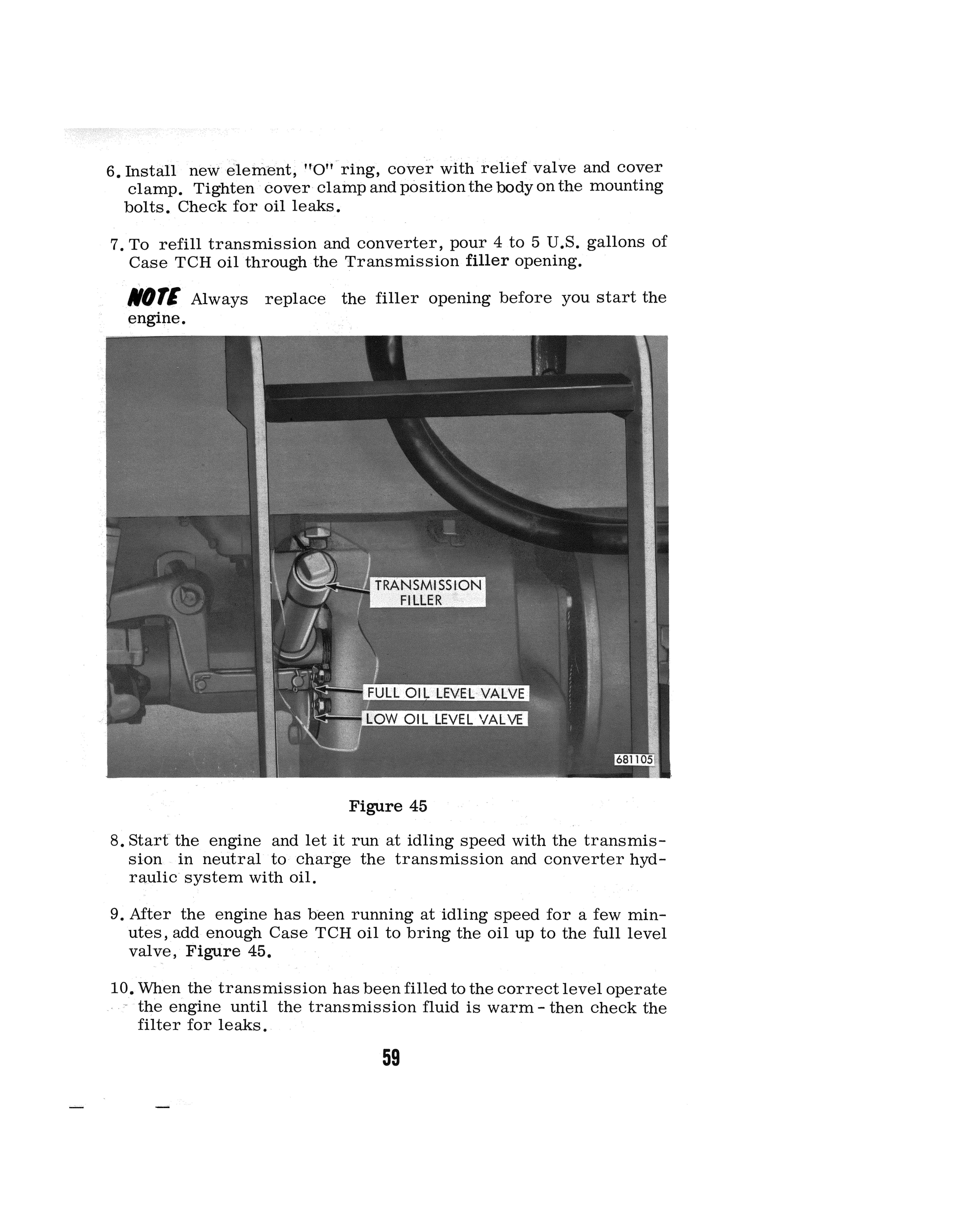
7. To refill transmission and converter, pour 4 to 5 U .s. gallons of
Case TCH oil through the Transmission filler opening. li/IJTI Always replace the filler opening before you start the
Figure 45
8. Start the engine and let it run at idling speed with the transmission in neutral to charge the transmission and converter hydraulic system with oil.
9. After the engine has been running at idling speed for a few minutes, add enough Case TCH oil to bring the oil up to the full level valve, Figure 45.
10. When the transmission has been filled to the correct level operate the engine until the transmission fluid is warm - then check the filter for leaks.
59
HYDRAULIC RESERVOIR
Change the hydraulic reservoir inlet filter element and clean the outlet filter after the first 20 hours of operation (Run In) and each time the reservoir oil i& changed thereafter. Drain and change (Hydraulic System) ------·--------- 1000 Hours Cleaning Interval (Reservoir Breather) --------------- 240 Hours Clean and Change Interval (Filters)------------------ 1000 Hours
Figure 46 Figure 47
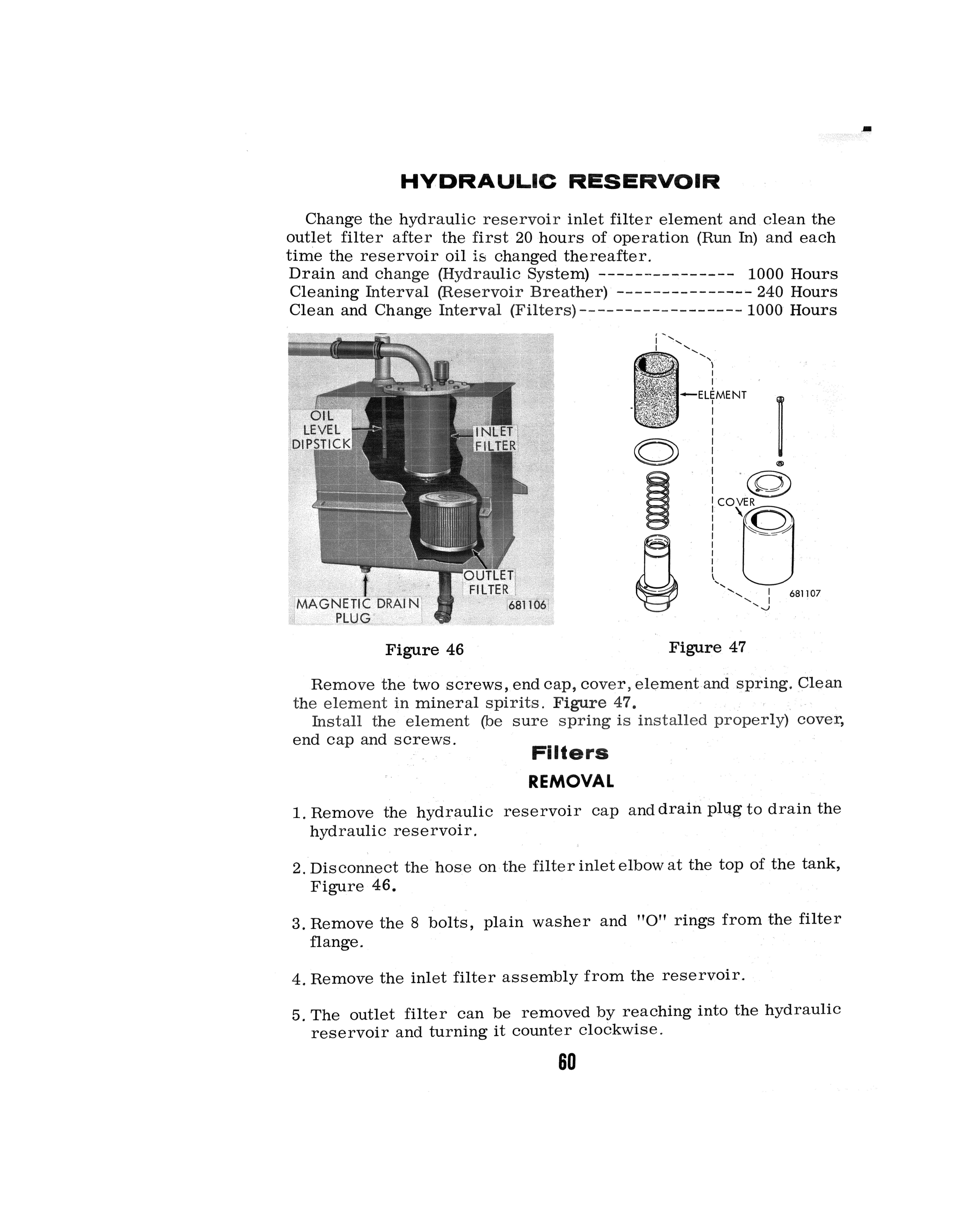
Remove the two screws, end cap, cover, element and spring. Clean the element in mineral spirits. Figure 47.
Install the element (be sure spring is installed properly) cover, end cap and screws. Filters
REMOVAL
1. Remove the hydraulic reservoir cap and drain plug to drain the hydraulic reservoir.
2. Disconnect the hose on the filter inlet elbow at the top of the tank,
Figure 46,
3. Remove the 8 bolts, plain washer and "O" rings from the filter flange.
4. Remove the inlet filter assembly from the reservoir.
5. The outlet filter can be removed by reaching into the hydraulic reservoir and turning it counter clockwise.
60
6. The outlet filter should be cleaned in mineral spirits.
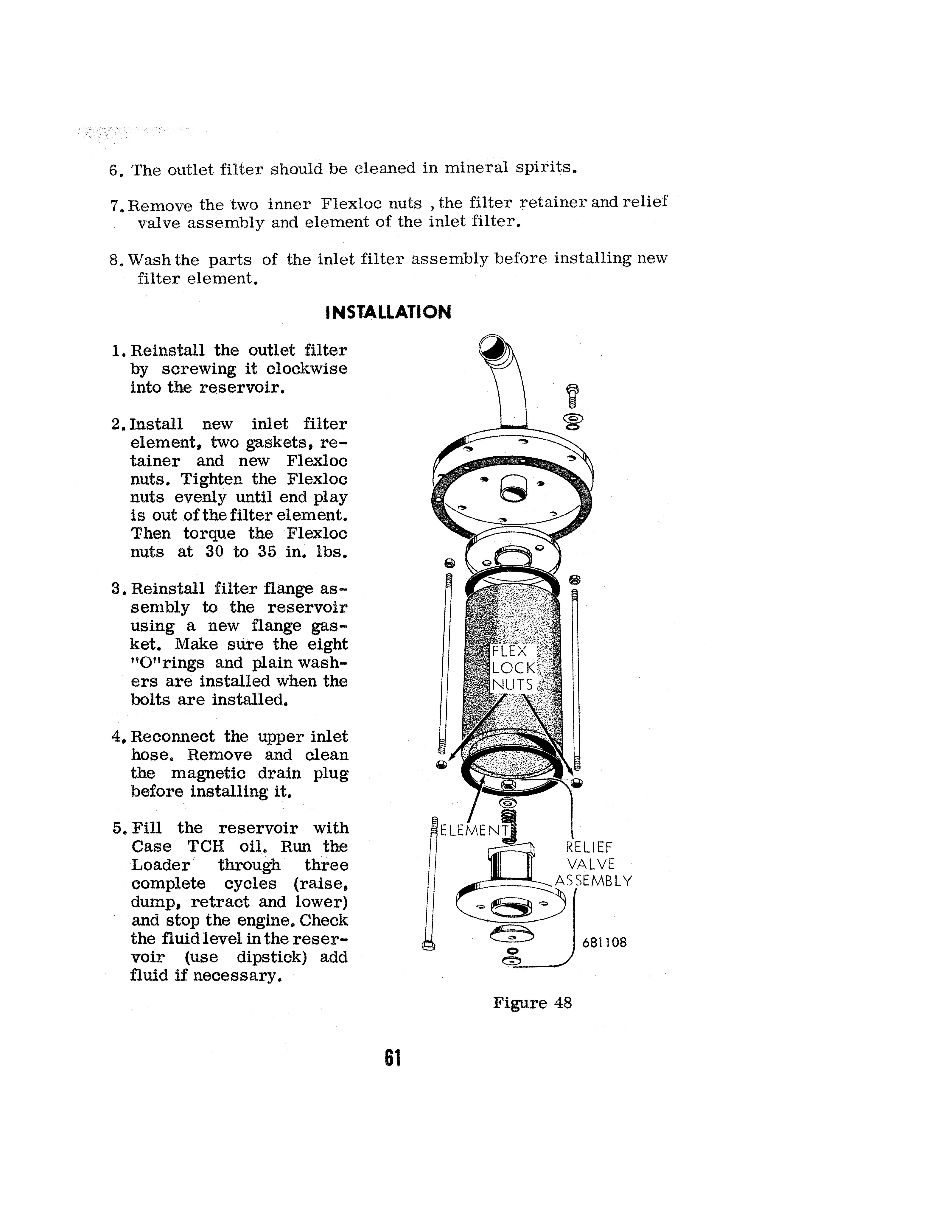
7. Remove the two inner Flexloc nuts , the filter retainer and relief valve assembly and element of the inlet filter.
8. Wash the parts of the inlet filter assembly before installing new filter element.
INSTALLATION
1. Reinstall the outlet filter by screwing it clockwise into the reservoir.
2. Install new inlet filter element, two gaskets, retainer and new Flexloc nuts. Tighten the Flexloc nuts evenly until end play is out of the filter element. 'Fhen torque the ·Flexloc nuts at 30 to 35 in. lbs.
3. Reinstall filter flange assembly to the reservoir using a new flange gasket. Make sure the eight 110 11 rings and plain washers are installed when the bolts are installed.
4, Reconnect the upper inlet hose. Remove and clean the magnetic drain plug before installing it.
5. Fill the reservoir with
Case TCH oil. Run the
Loader through three complete cycles (raise, dump, retract and lower) and stop the engine. Check the fluid level in the reservoir (use dipstick) add fluid if necessary.
Figure 48
61
BRAKE SYSTEM BREATHER
Remove the breather from the loader and disassemble, refer to Figure 49, by removing the screen retainer, screen and hair. Clean parts in diesel fuel and let dry. Lubricate hair by dipping in clean engine oil and let excess oil drain off. Reassemble and install in loader.
E::Jll, 681109
Figure 49
BRAKE SYSTE.M PILTER
Remove filter assembly from loader and disassemble, refer to Figure 50, by removing the six nuts, lockwashers and screws. Separate the two filter halves and remove the hair, gasket and screens. Clean all parts in diesel fuel· and let dry. Lubricate by dipping in clean engine oil and let excessive oil drain off. Reassemble and install in loader.
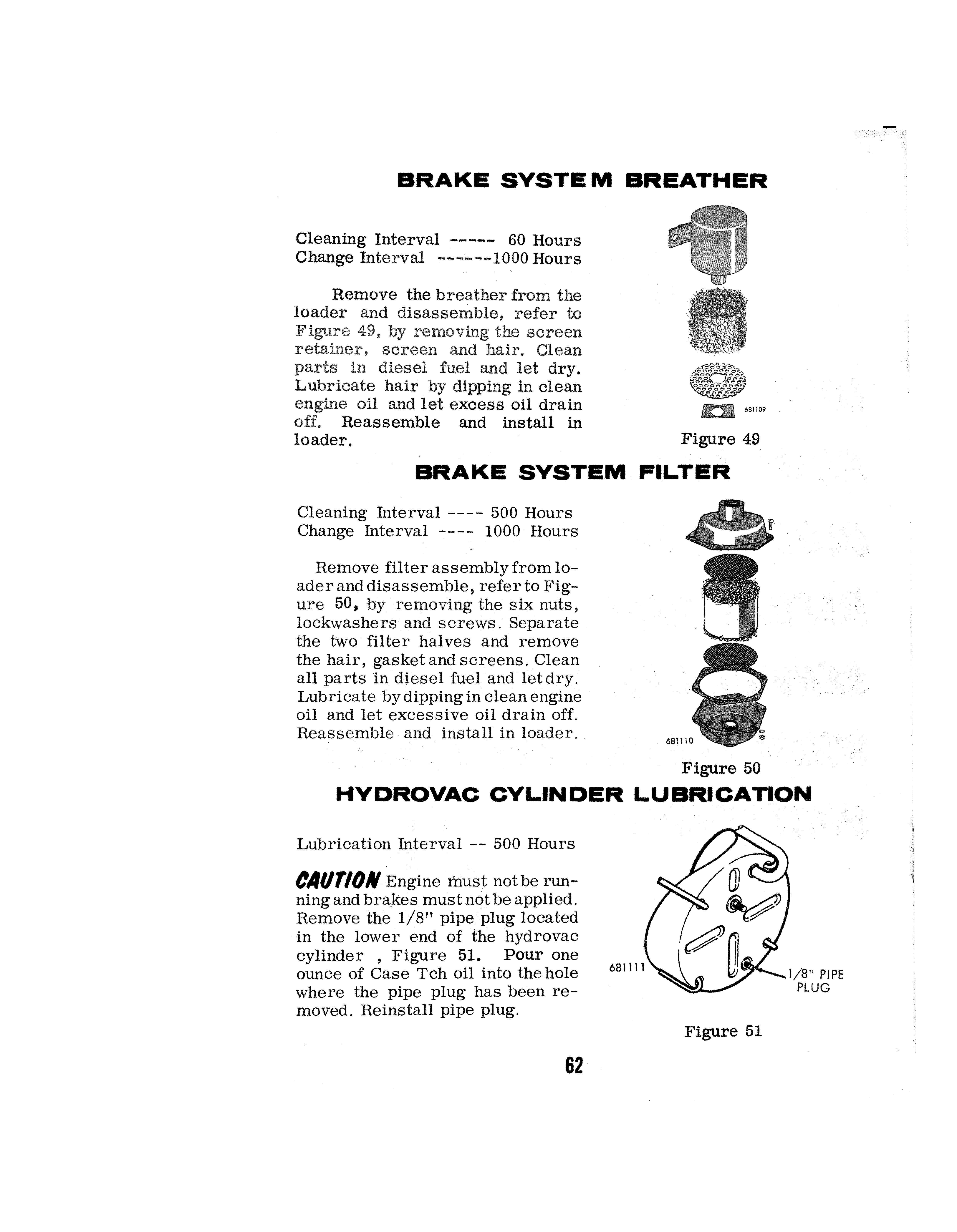
Figure 50
HYDROVAC CYLINDER LUBRICATION
Lubrication Interval -- 500 Hours
CAl/T/ON Engine must not be running and brakes must not be applied. Remove the 1/8" pipe plug located in the lower end of the hydrovac cylinder , Figure 51. Pour one ounce of Case Tch oil into the hole where the pipe plug has been removed. Reinstall pipe plug.
62
681111
Figure 51
1/8 11 PIPE PLUG