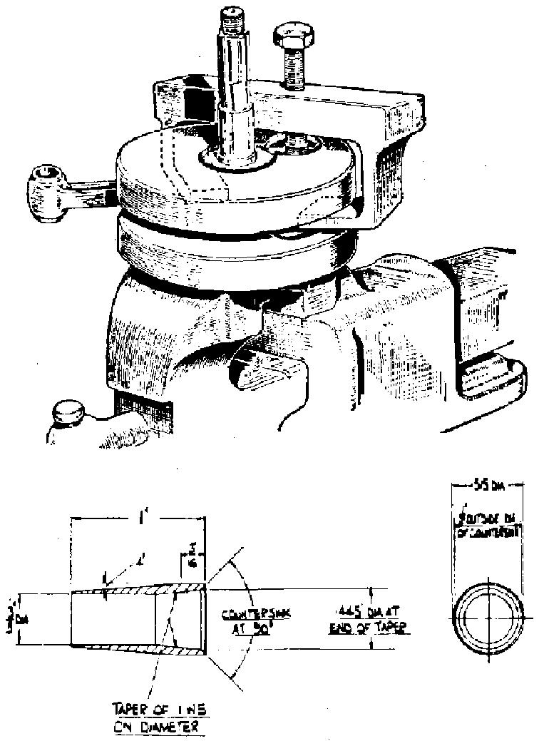
Removing the rear mudguard. Remove Âź" bolt securing rear guard to frame loop. Remove c" stud fixing bottom front of the guard to the frame lug. Remove bolt (3) and spacer, and chain guard. Remove bolt fixing rear chain guard at front. To remove the rear loop. Remove stud uniting rear loop to seat lug. Remove nut for stud on right side of rear loop. Remove this stud with brake pedal attached, take away the rear loop. Remove screw for plate in swinging arm. Release the two cotter pin nuts which locate the bearing tube. Push out the bearing tube. Swinging arm bushes. The two flanged bushes are housed in steel sleeves which are not supplied separately. The bushes are of the oilite type, but provision is made for lubrication via the centre plate screw (use heavy duty oil). If lateral movement develops at the wheel end this could be due to end float between the arm and the frame lug, particularly after long mileage, with a sidecar attached. Taking up side play. When it has been ascertained that end play is manifest, it is extremely difficult to absorb this movement by moving the bushes with the arm assembled in the frame, even with a sturdy support on one side of the arm. Whilst the bush in the opposite end is drifted in, there is always a certain amount of spring in the two extremities of the arm. It is therefore preferable to take the swinging arm away from the frame. To decide if the bearing tube or the bushes are worn, the spindle diameter is .9995"/.9990", the bush diameter in situ is 1.001". At the factory a pilot reamer 1" diameter is used for these two bushes, for correct alignment.
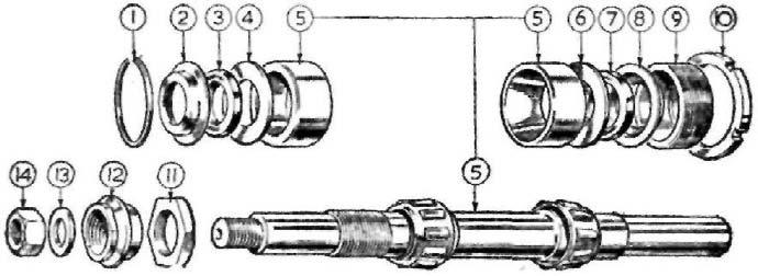
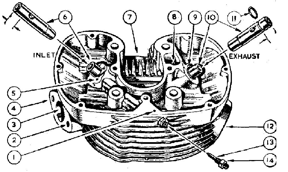
WHEEL BEARINGS Heavyweight Models The break down of the front wheel bearings: is shown in Fig. 26. It is vitally important to avoid tightly adjusting bearings of the taper roller type, as a crushing action takes place, the rollers will be damaged beyond further use. Should excessive movement suddenly develop, the bearing should be dismantled for inspection, for with correct adjustment and constant lubrication, these bearings will last in definitely. To dismantle the bearing. Remove the front wheel. Remove nut securing brake cover plate (12). Remove locating nut (11) and washer. Remove locking ring (10) and cover disc. Remove adjusting ring (9). Press out the spindle from the threaded end which will push out items 6-7-8 and bearing ring 5. The bearing ring will remain in the left side of the hub. To extract the bearing ring. Press in the washer (4) sufficiently far enough to permit the circlip (1) to be extracted. Use a piece of steel tubing passed through the hub and drift out the bearing sleeve, which will also eject the washer (4), oil seal (3) and collar (2). 87