25 minute read
Front forks


operating through the oil filler cap opening.
Completely unscrew the dutch cable adjuster.
Disengage, from the handlebar operating control lever, the clutch inner wire.
Pull cable, by its lower end, till removed from the machine, easing it through the frame cable clips while doing so. Dismantling shock absorber. Three thin and three thick rubbers are housed in the clutch centre and are located by the clutch hub steel plate (Fig. 20). For access, take out the three screws and move the plate to enable a screwdriver to be used to prise out the plate. To take out the rubbers use a. "C" spanner to turn the hub and compress the thick rubbers, which will come out easily after the thin ones have been extracted. Clutch bearing. The clutch hub is secured to the steel back plate by three spring studs and locknuts. After separating the back plate from the hub the bearing can be removed. When replacing, apply a little anti-centrifuge grease to the bearing.
FRONT FORKS Heavyweight, 350 c.c. Lightweight and 250 c.c. Scrambler Models
(The figures in parenthesis refer to Fig. 21) Stiff fork motion. First try the effect of releasing the two bolts securing the front mudgard to the fork slider (15). If normal movement is restored use washers between the mudguard and the slider to relieve side strain, or remove the guard and spread the sides. Try also releasing the four cap nuts (33) and work the forks violently to line up the inner tube and retighten the nuts.
If the fork motion is unduly stiff, and assuming the fork tubes are not bent by impact, it is possible that the black bushes (9) have swollen and are a tight fit on the tubes.
To rectify, dismantle the forks and ease down the inside diameter of the bush with emery cloth, until it is an easy sliding fit. Oil the fork tube, or use graphite before assembly. Fork noise on full deflection. Check the bottom cover tube (53) for contact with the slider extension (54), the cover tube may be deformed or canted. Remove the cover tube and set the tube face where it abuts against the fork crown (39) so that it is at complete right angles to the axis of the tube. The tube should be concentric with the slider extension. Usually there are score marks on the slider, under these circumstances. Rattle in forks. One of the damper rods (25) may be detached from the top anchorage. A low oil content will have the same effect. Fork spring rattle. Three neoprene rubber sleeves (Nos. 2, 4 and 5) are placed over the fork inner tubes, near the top. bottom and centre of the fork spring. If these sleeves have piled up at the bottom of the spring, the spring can rattle against the fork tube. Reposition or renew the sleeves to rectify. Apply some grease to the fork springs before refitting. Lateral fork movement. If the steering head bearing adjustment is correct and if there is a juddering effect when the front brake is applied, this can
be due to lateral movement caused by wear on the black fork bushes. The movement can be detected also by jacking up the front wheel clear of the ground when, by raising and lowering the front wheel, the movement will show up. Replace the bushes to rectify.
It is rare for the steel bushes to be affected, providing the fork oil content is not contaminated by abrasive. When replacing the bushes make sure the inside of the fork tubes is perfectly clean. Indifferent steering. If the machine is inclined to steer in an elongated figure of eight, this denotes unwanted friction in the steering which can be due to: (1) Steering head bearing over tightened. (2) There is friction, which cannot be released if a steering damper is used. (3) The steering head bearing is unduly loose and the fork stem is rubbing against the inside of the ball race. (4) The ball races are pitted, as a result of driving with a loose bearing adjustment (see 'Steering head adjustment').
In the case of (2) take out the bolt securing the steering damper plate to the frame. If the friction is removed, use washer(s) between the plate and the lug on the frame. Handlebars oscillate at low road speed. This trouble is not associated with the front forks, or wheel alignment. If the handlebars oscillate or 'wobble' at low road speeds and stops as the road speed increases, this is due to either one or both tyres not running true with the wheel rim and invariably becomes manifest after the tyres have to be changed. In the main the front tyre is responsible. Oil leaks from forks. First try the effect of tightening the slider extension (7) to compress the oil seal against the bush. If the leakage persists, replace the oil seal (8).
Should the leak take place at the lower end of the fork slider (15) check the damper tube bolt (31) and its washer for security. Loose head lamp brackets. The top fork cover tube (20) with lamp bracket incorporated is compressed between the handlebar lug (41) and the fork crown (39) with a rubber packing ring (18) interposed. If the rubber ring deteriorates or collapses, the tension on the tube will be reduced. Usually the trouble can be rectified without completely dismantling the front forks, by using a fork spring leather washer 021116 for each cover tube as packing.
Release the two nuts (45 and 46).
Tap upwards The handlebar lug (41).
Make a cut across one side of the washer and feed it round the fork tube, between the rubber and the fork crown. A little soapy water will assist the washer to slide over the rubber.
Re-align the head lamp and tighten the two nuts. Head lamp beam. If the lamp beam is out of parallel to the machine. thump the head lamp shell with the heel of the hand in the required direction. Bent fork inner tubes (17). The fork tubes can be straightened providing the set does not exceed 10° out of true.
Support the tube in 'V' blocks and use an Arbour press. NOTE—The fork tubes must be smooth and free from bruises and blemish, particularly in the part where the oil seal operates, otherwise the seal will be damaged beyond further use, with serious oil leakage. Fork damper conversion (Scrambler Models). For the 1962 season an improved type of fork damping was introduced in the Heavyweight forks fitted to Scrambler Models.
Earlier type forks can be converted by:
Dismantling the forks.
Dismantling the damper tubes (34).
Seal off, by welding, the small hole below the slot for the circlip (37).
Reduce the overall length of the top cover tube (16) to 1 z".
Reduce the overall length of the slider extension (7) to 3 d".
Use fork springs 016782.
Discard the buffer springs (10).
Fit two gaiters (dust protectors).
Fit four gaiter clips 042775. If new parts are required, instead of converting use: 2 Bottom cover tubes … 028046 2 Slider extensions … 028051 2 Damper tubes … … 028048 2 Main springs … … 016782 2 Gaiters … … … 020463 4 Gaiter clips … … 042775 Removing the front forks. Remove the two drain plugs (56) in turn and catch oil in a container.
Raise the front wheel with boxes under footrests.
Remove handlebars (use padding on the petrol tank to avoid damage),
Remove head lamp and disconnect speedo drive cable.
Remove front wheel, mudguard and stay.
Remove rubber grummets from tube bolts (22), also the two bolts. Use spanner 018667.
Remove lock nuts (24) and adaptor to release damper rods (25).
Remove domed nut (45) and adjusting nut (46).
Tap off the handlebar lug (41) using a rawhide mallet, until the lug clears the fork stem (40) and tubes, the forks can then be taken away as a unit, Watch for steering race ball bearings, 56 in number. Dismantling the forks. Hold the fork stem in a vice.
Remove slider extension (7) from the slider (15) by unscrewing from the slider.
Remove slider by giving it a sharp jerk downwards. The oil seal is a close fit in the top of the slider. If there is resistance in separating the slider, apply a little heat 1o the top part, which will expand and enable the slider to come away with ease, with the damper assembly attached,
Remove two Allen screws (38) then pull out the fork tubes. To remove steel bush. Prise out the circlip (12) and pull off the bush.
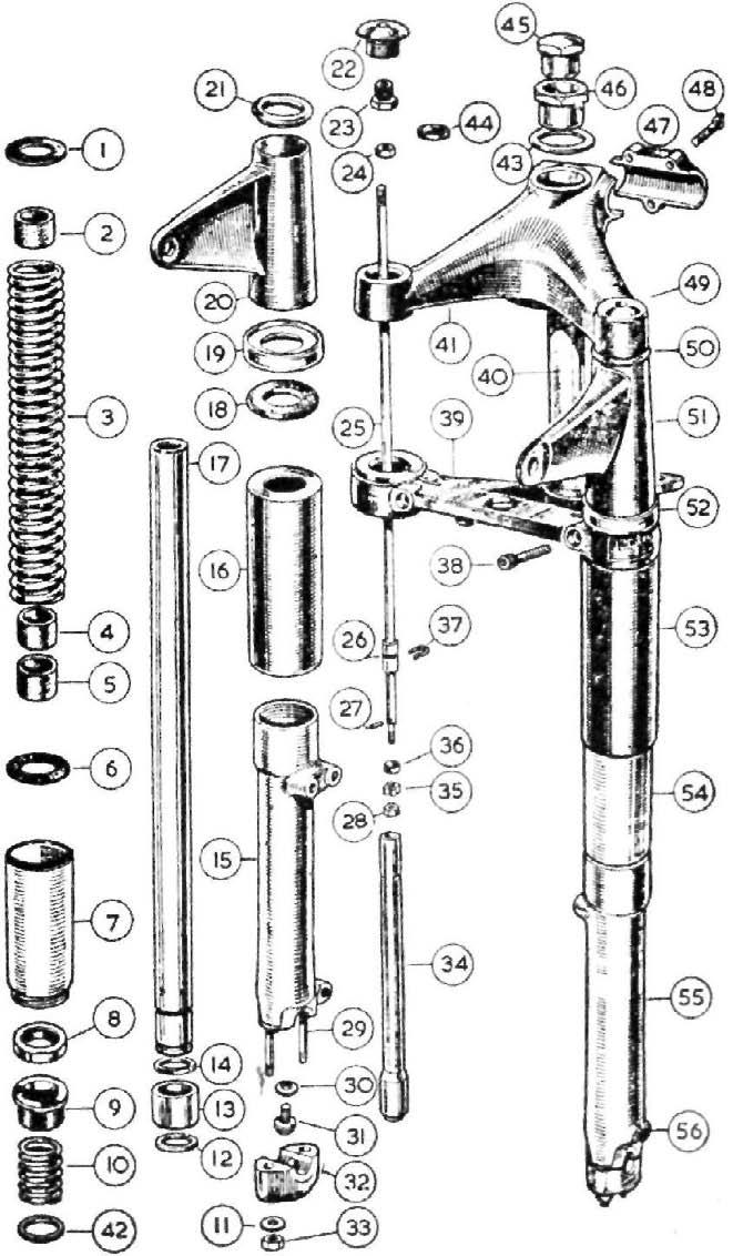
1 2 3 4 5 6 7 8 9 10 11 12 13 14 15 16 17 18 19 20 21 22 23 24 25 26 27 28 29 30 31 32 33 34 35 36 37 38 39 40 41 42 43 44 45 46 47 48 49 50 51 52 53 54 55 56 Washer, leather, for fork spring top seating. Buffer, rubber, for fork inner tube. Spring, main, for front fork. Buffer, rubber, for fork inner tube. Buffer, rubber, for fork inner tube. Washer, leather, for fork spring bottom seating. Extension for fork slider. Oil seal, for fork inner tube. Bush, top, plastic, for inner tube. Spring, buffer, for front fork. Washer, plain, for fork slider cap securing stud. Circlip, locating fork inner tube bottom bush. Bush, bottom, steel, for fork inner tube. Circlip, locating, fork inner tube bottom bush. Slider, for fork, with studs (right side). Tube, fork cover, bottom. Tube, fork, inner. Rubber ring for top cover tube housing ring. Housing ring, top cover tube. Tube, fork cover, top, right, with lamp lug. Spigot ring cover tube. Bolt, top, for fork inner tube. Adaptor. Nut, lock, for top end of damper rod. Rod, for fork damper. Sleeve, plunger, on fork damper rod. Pin, stop, for fork damper valve. Nut, lock, for damper valve seat. Stud, securing cap to fork slider. Washer, fibre, for damper tube bolt Bolt, fixing damper tube to slider. Cap. for fork slider. Nut, for fork slider cap securing stud Tube, for fork damper. Seat, for fork damper valve. Valve, for fork damper. Clip retaining damper rod sleeve. Screw, pinch, for fork crown. Fork crown, not sold separately. Stem, for fork crown, not sold separately. Lug, for handlebar and steering head. Collar for buffer spring. Washer for fork stem adjusting nut. Ring, rubber, sealing, for inner tube top bolt. Nut, lock, for fork stem. Nut. adjusting, for fork stem. Clip (half only), for handlebar lug. Screw, pinch, for handlebar clip. Bolt, top, for fork inner tube. Spigot ring top cover tube. Tube, fork cover, top, left, with lamp lug. Housing ring top cover tube. Tube, fork cover, bottom. Extension, for fork slider. Slider, for fork with studs (left side). Screw, plug, with fibre washer, for fork slider oil drain hole.
NOTE—Washer (43) deleted from assembly.
If the circlip becomes distorted during removal, replace it with a new one. To dismantle the damper tube. Use a thin wall box key to take out bolt (31) in the slider recess ½" across the flats, pull out the damper tube, with damper rod assembled.
Pull out the circlip (37), extract the damper rod with valve assembled. If the valve is taken off the rod, watch for small pin (27). TABLE OF FORK SPRINGS USED 250 c.c. Scrambler Model and Lightweight 350 c.c. Part No. 014950 Free length 11" Wire gauge .207" 350 c.c. Trials Model Part No. 014950 Free length 11" Wire gauge .207" Heavyweight Scrambler Model Part No. 021790 (CSR) Free length 11¼" Wire gauge .222" Part No. 016782 1962 (CS) Free length 12¾" Wire gauge .212" Heavyweight Touring Model Part No. 022369 Free length 11.90" Wire gauge .212" Heavyweight Sidecar Model Part No. 021789 Free length 12¾" Wire gauge .222" Buffer springs. All Models except 350 c.c. Trials Part No. 022079 Free length 2G" Wire gauge .192" 350 c.c. Trials, 250 c.c. Scrambler and 350 c.c. Lightweight Part No. 010360 Free length 2D" Wire gauge .187" To remove one fork tube. If attention to one fork tube only is necessary, the fork tube and components can be extracted by: (1) Taking out the front wheel, mudguard and stays. (2) Remove the domed nut (22), disconnect the damper rod and release the Allen screw (38).
Usually the fork tube is a close fit in the two top members (39 and 41), thus to avoid damage to the internal thread in the fork tube, a draw bolt is required, which is also used to pull back the tube. The tools for the large, also small, diameter fork tubes are shown in Fig. 22.
Insert the tool into the fork tube which can now be driven out.
If at this stage the slider has to be removed, and if the tube is held in a vice, use a suitable clamp and hold the tube at the lop and away from the oil seal travel. Assembling the forks (without a draw bolt). Hold the fork crown in a vice.
Assemble a fork tube with its components as described in 'Assembling the forks with a draw bolt'.
Push the fork tube into the fork crown,
Insert the key 018667 in the Allen screw.
With one hand pull up the tube until it protrudes 6½" and quickly tighten the Allen screw.
Then assemble the second tube in a similar manner.
Fit the crown races with bearings as previously described and pass the fork stem through the frame.
If assistance is available hold the forks in position, assemble the top
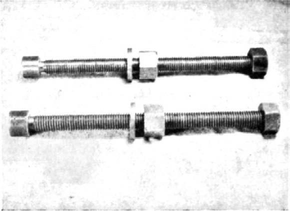
FIG 22 Fork tube tool frame race and bearings.
Alternatively, place a box under the forks to support.
Assemble the two top cover tubes and handlebar lug, connect the damper rods to the top bolts.
Engage the top bolts as far as possible, then release the clamp screws.
Firmly tighten the top bolts then the clamp screw. (See 'Special precautions').
Adjust the steering head bearings and fill oil to each fork tube. Steering head adjustment. The steering head frame races are of the floating self-aligning type and have spherical seats. Therefore they do not fit tightly in the head lug.
Occasionally test the steering head for correct adjustment by exerting pressure upwards from the extreme ends of the handlebars.
It is particularly important that the adjustment is tested after the first 100 miles because of the initial settling down that always occurs in that period.
Should any shake be apparent, adjust the steering head bearings. Adjust steering head bearings by: Jacking up the front of the machine so that all weight is taken off the front wheel. (A box under each footrest serves that purpose).
Slacken the two fork crown Allen screws.
Slacken the domed nut at top of the steering column.
Screw down the nut underneath the domed nut a little at a time and while doing so, test the head assembly for slackness by placing the fingers over the gap between handlebar lug and frame top lug, at the same time exerting upward pressure by lifting from the front edge of the front mudguard. Tested in this? manner the slightest slackness is discernible.
Continue to tighten the lower adjusting nut until no perceptible movement can be felt and yet the steering head is perfectly free to turn, then tighten down the domed nut in order to lock the adjustment.
Securely tighten the two fork crown Allen screws (this is very important).
Remove packing from under footrest,
Special precautions: It is vitally important to firmly and positively tighten the two Allen screws (38) which clamp the fork tubes.
Movement between the tubes and the fork crown (39) will cause 'fretting' which can weaken the tube,
Never attempt to repair a fork slider after damage by impact, by welding. Where serious damage has occured after frontal impact, carefully examine the slider for latent cracks, Steering angle. When the Duplex tube frame was introduced in 1960, a slight alteration to the steering angle was made to improve steering, also road holding. The parts affected are the fork crown and stem and the handlebar lug.
Whilst the difference between the old and new parts is exceedingly small, it does affect interchange of the fork parts individually, viz., whilst both the new type handlebar lug with fork crown can be used on early models as a pair, they cannot be used separately.
As the new parts are virtually identical in appearance, they can be identified by the figure 6 stamped on each part. Fitting a sidecar. To accommodate the extra load the solo fork springs should be exchanged for a stronger type (see 'Table of fork springs'). In the case of a heavy type sidecar, the rear suspension springs must be changed also. Fit a steering damper to offset heavy steering and stop handlebar wobble.
See 'Technical Data' for engine sprocket. To re-assemble the forks (using a draw bolt). Check steering head races for pitting or damage. Pack the lower crown race with grease and fill with 28 steel bearings, put the lower frame race over the stem to retain the bearings. Pack the top frame race with grease, fill with 28 bearings and place it in the frame.
Take up the fork crown and pass it through the frame, fit the handlebar lug and hold these two members together by fitting the nut (46).
Assemble the top cover tubes in the sequence shown in Fig, 21 and fit them between the fork crown and handlebar lug. It may be necessary to release the nut (46) to do this, then retighten this nut to clamp the cover tubes. The steering head adjustment can be dealt with later. Assembling the fork tube. With the fork tube horizontal apply a little oil to the bottom end of the tube.
Fit the oil seal, metal backing towards the top, use a rotary motion at the bottom end of the tube.
Fit the black bush, flange upwards, buffer spring and collar (42).
Fit one circlip, the steel bush and second circlip.
Fit from the top end, slider extension, leather washer (6).
Take up the fork slider, with damper rod assembled, pass it over the fork tube from the bottom end, engage the slider extension.
Fit rubber sleeves, spaced over fork spring length.
Fit main spring, leather washer and top tube (16).
Fit the tube assembled into the two top members, as far as it will go, tighten the clamp screw lightly to hold the tube in position.
Fit the draw bolt, well engaged in the tube and pull the tube home.
Firmly tighten the clamp screw to stop the tube from moving and take away the tool.
Fit damper rod (see 'Changing fork springs') to tap bolt and firmly tighten. Fill each tube with 6½ ozs. (186 c.c.) SAE 20 oil. Changing the fork springs. The fork springs can be examined, or exchanged, without entirely dismantling the forks. The draw bolt, as illustrated, is necessary for this operation.
First detach the front brake cable at the handlebar end.
Take out the two fork tube nuts (49), disconnect damper rods.
As the front wheel spindle is attached to the forks, it is obvious that the fork tubes are extracted simultaneously. To do so, engage the fork tool in the tube (a fair way down) and drive the tube downwards a small amount.
Transfer the tool to the other fork tube and treat it likewise,
Repeat the operation, transferring the tool from one tube to the other, until they are clear as depicted. To reassemble. Refit the assembly and enter the tubes as far as they will go. The tubes should be parallel with the covers. Run back the large nut on the tool and engage it in one of the tubes. Run down the tool nut and tighten, to pull the tube back a slight amount, thus reversing the method used for extracting the tubes.
An old engine push rod, with the adjuster cup taken out can be used to bring up the damper rods. Alternatively, use a loop of copper wire. Assemble the damper rods to the top anchorage and firmly tighten the lock nuts. Refit the tube top bolts, firmly retighten the two clamping screws.
1964-1966 Front Forks
Lubrication. Use one of the grades of oil, S.A.E. 20 as shown in the table of lubricants. The normal oil content is five fluid ozs. (142 c.c). Attention is only necessary at the first 1,000 miles and again at 10,000 miles when the oil should be changed by draining. An exploded drawing of the front forks is shown in Fig. 24 from which it will readily be seen that the fork springs abut against the filler plugs (34), before removing these plugs weight must be taken off the front wheel, by placing the machine on its central stand to avoid the forks collapsing. To drain the forks. With the machine on the central stand: Unscrew the two filler plugs (34). Have available a container to catch oil drained, then remove the drain plug screw (7) with its washer, with the container under the fork leg. If the wheel is inclined to one side, draining will be more complete. Deal with the other fork leg in a similar manner. Filling oil. It will be seen that the air space between the fork spring, and the inside of the tube is very close; therefore fresh oil must be filled with
extreme care, to avoid losses by spilling. Use a measured container for the correct content of 5ozs. Replace the drain plugs before filling, also firmly tighten the filler plugs after. Steering head adjustment. On a new machine the filler plugs (34) should be checked for tightness due to settling down, check as well the steering head bearing at the first 100 miles, and then occasionally, as the mileage increases. Using the machine with movement in these bearings will damage the races, Movement in these bearings can usually be detected when the front brake is applied. To check, raise the front wheel well clear of the ground, with a box under the crankcase. Try to raise or lower the front wheel with one hand and use the fingers of the other hand encircling the handle bar lug where it meets the frame, when movement can be felt. To adjust bearings a thin open ended spanner 1 a" across the flats is needed. First release the tube clamping stud nut (28), unscrew the stem nut (37) slightly. Use the thin spanner on the sleeve nut (30) and manipulate as necessary. The bearing should be devoid of play with free movement. Retighten the column nut, also the clamping stud nuts, Steering lock. The lock is pressed into the handle bar lug, and can be removed by driving it out from underneath. A number is stamped on the bottom of the lock for key identification. Dismantling the forks. The forks can be removed as a unit, or the fork legs can be removed individually. To take out one fork leg remove the front wheel as described elsewhere. Take off the front mudguard with stays. Release nut for pinch bolt (28). Remove filler cap plug (34), disconnect it from the damper rod, by using two spanners.
The fork inner tube can now be drawn downwards clear of the handlebar lug and fork crown. If the tube resists removal fit back the filler plug without being connected to the damper rod, screw in a few turns, then give it a few sharp blows with a soft faced mallet to separate the tube from its taper fixing in the handlebar lug. To remove the forks as a unit. Follow the instructions given for removing a, fork leg, as far as disconnecting the filler plugs from the damper rods. Proceed by taking off the headlamp leaving it suspended by the loom. Separate the control cables from the levers, and remove handlebars. Remove the column nut (37) then give the underside of the handlebar lug one or two blows with a mallet until it is clear of the fork tubes. At this stage support the ends of the forks, for after removing the sleeve nut (30) the forks will drop out. Watch for steel balls for the races, there are 18 in each race (36 in all) if a steering damper is fitted detach the fixed plate from the frame. To dismantle a fork slider. Remove from the fork slider the bolt fixing damper tube (11). Unscrew the bottom cover (23), holes are provided for a C spanner. Take away the fork slider (5),
The damper tube with the fork spring can be extracted, from the tube. To dismantle further, take off nut securing fork spring, unscrew the damper tube cap (16) with a tommy bar through the holes in the damper tube, for if this is held in a vice it will distort and become useless. The damper assembly sequence is clearly depicted in Fig. 24. NOTE—When removing the oil seal, sealing washer and flanged bush pass
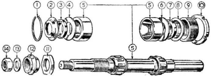
FIG 23 Exploded view of front forks—1959 (Lightweight type)
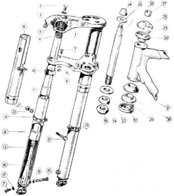
1 Fork, H. 2 Inner tube top screw. 3 Inner tube top screw fibre washer. 4 Top cover tube. 5 Inner tube top adaptor. 6 Main spring. 7 Drain screw. 8 Top cover tube shakeproof washer. 9 Top cover tube fixing screw nut. 10 Oil seal. 11 Assembled part. 12 Assembled part. 13 Slider extension. 14 Damper tube. 15 Damper tube retaining screw. 16 Damper tube retaining screw fibre washer. 17 18 19 21 22 23 24 25 26 27 28 29 30 31 32 33 34 35 Drain screw fibre washer. Mudguard clip left. Mudguard clip right. Mudguard clip bolt. Mudguard clip bolt washer. Mudguard clip bolt nut. Nut, domed top. Washer top domed nut. Head stem. Spacer for head stem. Adjusting race. Balls steering. Frame race top and bottom. Dust cover for ball race. Crown race. Washer head stem bottom nuts. Head stem adjusting nut, bottom. Head stem lock nut, bottom.
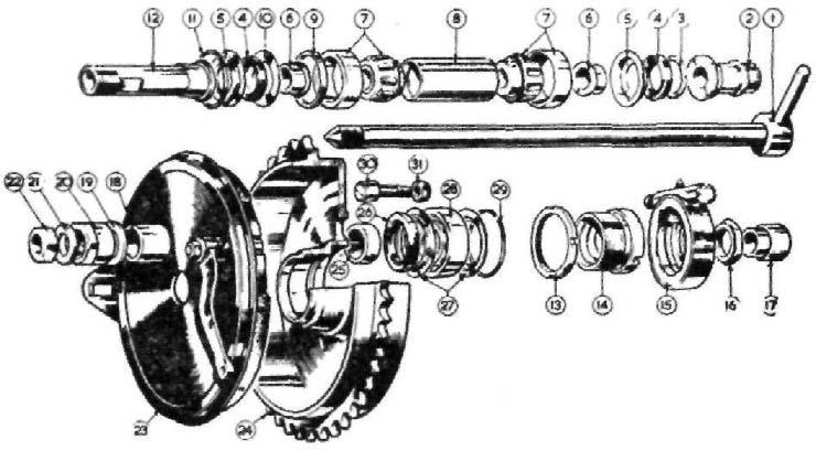
1964-66 Front Fork Assembly
1 Fork main tube 2 Main tube bush 3 Main tube bottom bush 4 Main tube bottom bush circlip 5 Fork end left hand 6 Fork end right hand 7 Fork end drain plug 8 Washer for plug 9 Oil damper tube 10 Oil damper rod 11 Oil damper tube bolt 12 Washer for bolt 13 Washer for tube 14 Nut for rod top 15 Nut for rod bottom 16 Damper tube cap 17 Piston locating peg 18 Oil damper valve cup 19 Oil damper valve cup slotted ring 20 Main tube lock ring with cup 21 Main spring 22 Main spring locating bushes 23 Spring cover tube 24 Soring top cover tube securing plate 25 Screws securing plate 26 Crown lug complete with column 27 Pinch stud for crown lug 28 Nut for stud 30 Fork head race adjuster nut 31 Top cover left hand 32 Top cover right hand 33 Main tube top cover ring 34 Fork main tube filler and retaining plug 35 Washer for plug 36 Fork head clip 37 Fork crown and column lock nut
FIG 24
them along the fork tube and take off from the top end past the taper end, if the oil seal is to be used again. Assembling the forks. It will be apparent from the dismantling instructions given that there is nothing complicated in the fork assembly and if the reverse sequence is used, no difficulty should occur with the following precautions.
The fork tube, where the oil seal operates, must have a smooth finish and free from blemish.
The oil seal is fitted from the top of the tube, with the visible spring facing downwards against the flange for the bush.
The damper tube cap also the damper tube fixing bolt must be properly tightened.
Finally tighten the bottom cover (23) when the front wheel has been put back.
Fill 5 ozs. of S.A.E. 20 oil to each fork leg.
Front Forks 250 c.c. Model
An exploded view of the front forks, is shown in Fig. 23. Dismantling the forks. Remove the front wheel as described in 'Wheels and brakes' section.
Take off the head lamp front and detach bulb holders.
Disconnect the speedometer drive cable.
Detach the black and blue cable plugs.
Detach ammeter wires and dip switch cable.
Detach handlebars.
Detach front mudguard by taking out the two clip bolts, expand the clip a trifle to avoid damage to enamel.
Detach drain plugs (7) and catch the oil.
Detach head stem nut (24), watch for three shim washers.
Detach steering head stem and support the forks. Watch for head bearings (29), set of 39 and take away forks. Support the forks in a vice, take out screw (2), and pull off the bottom slider extension (13) with fork spring attached.
Detach two screws securing top cover tube, and take tube away.
Detach bolt (15), pull out fork spring and damper. The spring is screwed on to the damper, also the top spring anchor. Removing the oil seal. The oil seal will come away attached to the slider.
Secure the slider in a suitable clamp fixed in a vice.
Bring the mudguard clip up to the oil seal body, using a series of light blows with a hammer directed on to the ears of the clip. Move the clip round the seal body whilst doing this to remove it squarely. Re-assembling the front forks. The work involved is straightforward with the following precautions: (1) After fitting the cover tubes leave the two fixing screws loose. When the forks are assembled and working correctly, retighten the screws. (2) Assemble the oil seal to the slider squarely. (3) When refitting the slider bring the seal up to the bush. Use a small radio-type screwdriver or similar tool, insert the tool between the oil seal rubber and the fork bush. Use a rotary motion pressing gently against the