17 minute read
Wheels and Brakes

BRAKES
Lightweight Scrambler and 350 c.c. Trials Model
The front brake. The front brake is dimensionally the same as the rear brake.
Brake adjustment to compensate wear on the linings is effected by finger adjustment on the rear brake rod and front brake cable.
After considerable mileage, brake lining wear will adversely affect the leverage of the brake shoe expander.
To restore the leverage without relining the brakes, packing washers 000174 are used under the heat treated thrust studs. The washers used must be uniform in thickness, to ensure both brake shoes make contact with the drum simultaneously.
Heavyweight Models
Front brake. The front brake drum is cast in the hub and is machined after the wheel has been built, thus ensuring concentricity. During the process of lacing the wheel spokes, slight distortion can take place. If a wheel is rebuilt and brake efficiency is impaired, the brake drum should be skimmed to restore efficiency. Front brake cover plate. The brake cover is located by a nut 021931 at the back of the plate. This nut is adjusted so that the plate when assembled is flush with the edge of the hub shell. The plate lock nut 018071 is fitted with the hexagonal side against the plate. Water enters the brake. Check the location of the cover plate for correct position. Centralising the brakes. For maximum brake efficiency both brake shoes must contact the drum simultaneously when the brake is applied. Release the spindle nut, also the cover plate lock nut. Closely adjust the brake cable and put pressure on the brake lever. Whilst maintaining the pressure, retighten the lock put and spindle nut, this action will allow close adjustment of the brake shoes, without binding.
In exceptional cases the hole in the plate for the wheel spindle can be enlarged a slight amount. Removing the plate lock nut. If there is difficulty in releasing this nut and a vice is not available, put the wheel spindle into one of the fork slider caps, with wheel outside the forks and tighten the clamp nuts. which will act as a temporary vice. Rear brake. The rear brake drum is detachable. The front and rear brake shoes are interchangeable. See details for Scrambler brake for brake shoe adjustment.
WHEELS AND BRAKES 1963 Heavyweight Models
For the 1963 season all models were fitted with journal type wheel bearings, as opposed to the taper roller type previously used. No adjustment to these bearings is possible, or necessary; the only attention needed it to renew lubricant and clean every 10,000 miles, the bearings being lubricated on initial assembly. The front wheel. Two journal bearings type RMS 6 are used in the front
hub with a pull-out wheel spindle. A super oil seal is fitted against the bearing on the brake drum side to prevent grease entering the brake drum.
A similar oil seal is used in the bearing retaining sleeve at the opposite end of the hub, also a felt sealing ring.
The hub is packed with grease during assembly, subsequent lubrication should not be necessary until the machine has covered 10,000 miles, when the bearings can be re-greased if necessary. (See table of lubricants.) To remove the front wheel. With the machine on the centre stand, disconnect the front brake cable from the brake expanding lever, then remove the bolt (securing the torque stay) from the brake plate and release the spindle nut 000001.
Remove the four nuts securing the detached fork slider caps, take off both slider caps, when the front wheel can be removed. - Dismantling the front hub. Both wheel bearings are a press fit into the hub.
To avoid “scruffing” the bearing housings in the hub during the process of removing and refitting the bearings, the hub must be gently heated to cause the hub material to expand and relieve the interference fit. Have available a new oil seal 029263.
With the front wheel removed, take off the spindle lock nut 029246, pull out the spindle and brake plate.
Remove oil seal collar 029262.
Prise out the oil seal 029263.
Gently heat the hub in the vicinity of the wheel bearing 029264 (do not concentrate the applied heat in one place) drop the hub on to a flat wood bench, when the bearing will move away from the centre of the hub. Invert the hub, use a suitable drift to drive out the bearing, placing the drift on opposite sides of the bearing so that it is extracted parallel with its housing.
Pull out the bearing spacing tube 029266.
Remove the lock ring lefthand thread 029238, also the hub disc.
Unscrew the bearing retaining sleeve 029269.
Re-heat the hub and drift out the second bearing as described for the first one. To assemble the front hub. Gently heat the right side of the hub, insert the bearing and press it fully home by screwing in the bearing retaining sleeve (lefthand thread). Invert the hub and pack some grease against the bearing just fitted. Insert the bearing spacing tube and fill some more grease to the hub. Re-heat the brake side of the hub, insert the bearing and press it fully home.
Fit the oil seal (metal backing outwards) flush with the hub.
Fit the hub disc and secure it with the lock ring.
Insert the oil seal collar into the oil seal, put the spindle through the brake plate and the hub and tighten the spindle fixing nut. Refitting the front wheel. Refit in the reverse sequence given for removal, with the following precautions: Ensure the bolt fixing the brake torque arm to the brake plate is securely tightened. Do not over tighten the four nuts securing the two fork slider caps.
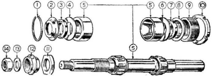
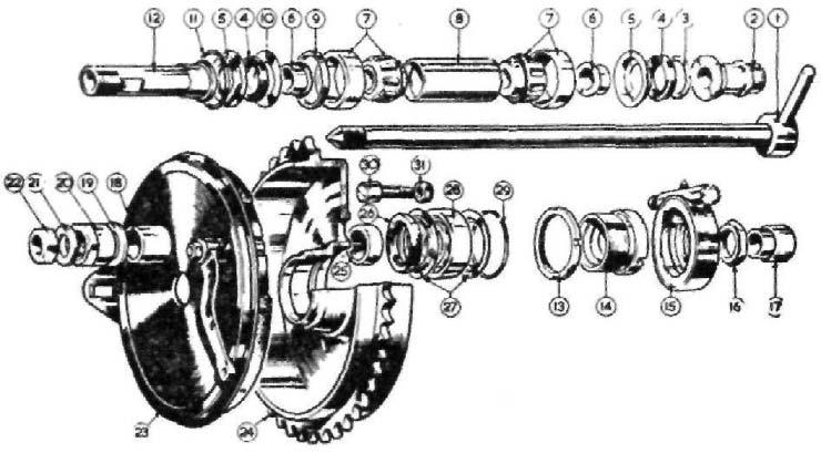
FIG 28 Rear brake and wheel bearings, de-luxe models
1 2 3 4 5 6 7 8 9
10 11 12 13 14 15 16 Withdrawable wheel spindle Speedometer gear box sleeve Ring retaining oil seal (small) Oil seal Cup for oil sseal Oil seal distance piece Taper roller bearing complete Spacer between bearings Bearing spacing collar (brake side) Ring retaining oil seal (large) Circlip Brake drum dummy spindle Lock nut for adjusting ring Adjusting ring Speedometer gear box complete Speedometer gear box fixing nut 17 18
19 20 21 22 23 24 25
26 27 28 29 30 31 Spacer for withdrawable spindle Outer spacer for brake cover plate Washer for cover plate fixing nut Brake cover plate fixing nut Spindle end washer Spindle end nut Brake cover plate complete Rear brake drum Inner spacer for brake cover plate Brake drum bearing oil seal Brake drum oil seal washers Brake drum ball bearing Circlip retaining bearing Driving peg (5 off) Nut securing driving peg (5 off)
The rear wheel. A journal type bearing RMS 5 is used in the right side of the rear wheel hub, also a roller type bearing CRL 8 in the brake drum. The pull-out spindle passes through both bearings and the hub.
The wheel is detachable from the brake drum. To remove the rear wheel. Using the box key 029385 (supplied with the tool kit) remove the five extended nuts 029235.
Remove the wheel spindle nut 014869, pull out the wheel spindle, when the speedometer drive will come away from the hub with the drive cable attached.
Slide out towards the rear spindle distance piece 029243, the wheel will now come away from the brake drum.
If the machine is leaned over on the right side, the wheel will come out under the brake drum. To re-fit the rear wheel. Put the wheel back, insert the spindle through the frame and hub (without the distance piece of speedometer drive), which will help to line up the wheel.
Fit the five extended nuts and screw home lightly.
Take out the wheel spindle, fit the distance piece, put back the spindle with speedo drive through the hub and frame.
Position the speedometer drive and cable, re-lit and tighten the wheel spindle nut. Now firmly re-tighten the five extended nuts. Dismantling the rear hub. With the rear wheel removed, unscrew the bearing retainer sleeve 029236 (lefthand thread) together with the oil seal and distance piece, which will come away with the retainer. Invert the hub, extract the circlip 029234 (use round-nose pliers) take out the distance piece 029231.
Gently heat the hub in the vicinity of the bearing 029233, drift out the bearing. Removing the oil seal 029237. Tap the oil seal distance piece out of the bearing retainer, which will dislodge the oil seal. Rear brake drum. To remove the roller bearing, use a suitable drift or a piece of steel tube to drift out the roller bearing. Invert the brake drum and press out the oil seal.
WHEELS AND BRAKES 1964-1966
To remove the front wheel. With the machine on the central stand: Detach the brake cable from the expander lever. Detach the brake cable adjuster from the brake plate. Detach the right hand spindle nut. Release the pinch stud in left fork slider end. Take the weight of the wheel by the left hand, pull out the wheel spindle. The wheel can be taken out of the forks. To refit the wheel. Reverse the procedure described for removal, with the following precautions. Remove traces of rust from spindle and grease. Exercise care to correctly locate brake plate in the fork slider. Do not tighten unduly the slider pinch bolt, overtightening can cause a fracture. NOTE—If the fork motion is stiff after refitting the wheel, slack off the spindle nut and work the forks up and down (the fork tubes will take up alignment), then retighten the spindle nut. To remove the rear wheel. The rear wheel is detachable from the brake drum. With the rear wheel clear of the ground: Take out the three rubber grummets (4). Remove the sleeve nuts (8) which retain the wheel to the brake drum. Unscrew the wheel spindle (20) and remove it. Take away the distance piece, between the speedometer drive, which will come away also, there is no need to separate the cable from the drive. Pull the wheel away from the driving studs in the brake drum. Incline the machine to the right side, then pass the wheel under, clear of the machine.
L WHEE T FRON
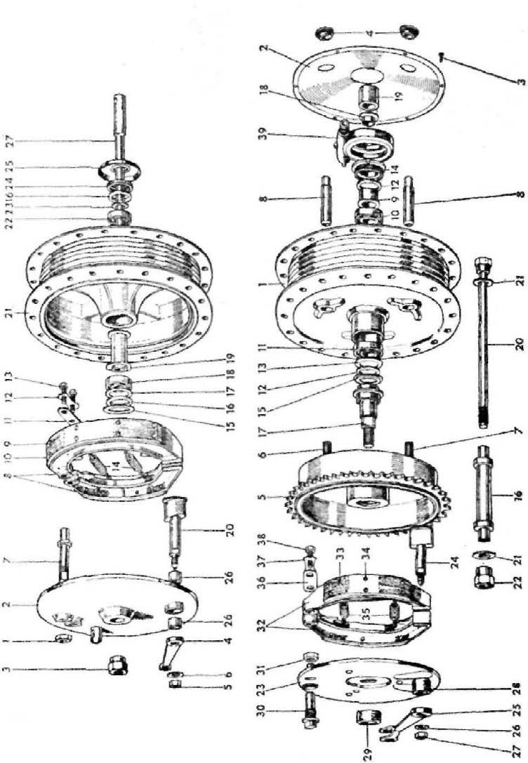
FIG 29
To remove the brake drum. With the rear wheel removed: Take off the brake rod hand adjuster, then remove the rear chain connecting link. Release the nuts securing the dummy spindle, pull back the brake drum clear of the fork ends. To dismantle front hub. The wheel hubs are packed with grease during initial assembly, and should not need further lubrication for at least 10,000 miles, when the hubs should be dismantled for cleaning and fresh grease used. To dismantle the front hub, with the wheel removed take away the brake plate with brake shoes.
Unscrew bearing lock plate on left side of hub, holes are provided for a peg spanner or use a punch. If the plate resists removal use a little heat which will facilitate removal, take out felt sealing washer and distance piece.
To eject the bearings use a drift through the brake side (the front wheel spindle can be used for this purpose) when a few light blows from a mallet will drive out the bearing until it is clear of the hub, and no more, as the other bearing goes into the hub during this process.
Take out the spindle, or drift, invert the wheel and repeat the process to eject the double bearing which will bring with it the large steel washer. the felt washer, also the thin steel washer. Assembling the hub. Clean and repack both bearings with fresh grease (see table of lubricants). Press into the left side of the hub the single bearing, fit the distance washer (flat side against the bearing), then the felt washer and secure with the lock plate.
Invert the hub, insert the distance tube (small end first) against the bearing.
Enter the double bearing square with the hub, use a drift through both bearings and drive home until the bearing abuts against the distance tube.
Fit the smallest of the two washers, the felt washer, then the large steel washer.
With a suitable punch peen the hub material, where it joins the washer in three equi-distant positions to retain the washer. Rear hub dismantling. With the wheel removed, remove the speedometer drive lock ring (this has a lefthand thread), take out felt washer and distance piece. To eject the bearing use the wheel spindle with its washer also the distance piece that goes between the speedometer drive and the frame placed on the spindle. Partially drive out the bearing until it abuts against the reduced diameter inside the hub. Take out the spindle, use a short length of steel tubing with the outside diameter slightly smaller than the inside diameter of the bearing and drive out the bearing.
Invert the wheel, then drift out the other bearing, which will take with it the steel cup, felt washer and the thin steel washer. Assembling the hub. Deal with the bearings as already described and assemble by first fitting the single row bearing, in the reverse order described for dismantling, with the following precautions: when tightening the lefthand lock ring avoid damage to the slots for the speedometer drive. Finally "peen" the hub dished washer to the hub. The hub assembly sequence is shown in Fig. 29. Dismantling the brake drum. A bearing is not used in the brake drum:
when the spindle nut is removed together with the spacer and washer, the spindle can be taken out. Balancing the wheels. At high speeds, if the tyres are out of balance, the steering can be affected and in extreme cases the front forks can 'flap' at maximum speed. As oil seals are used on both wheel spindles, the wheel cannot be accurately balanced until the friction caused by the seals is removed. The courses open are: (1) Remove the oil seals. (2) Obtain two ball races with an internal diameter sufficiently large enough to take the wheel spindle, mount the wheel on two boxes.
If the wheel is correctly balanced, it should remain stationary in any position in which the wheel is placed. The most likely out of balance position will be where the valve is situated or where a security bolt is fitted. The heaviest part will of course come to rest at 180° or 6 o'clock. To counter-balance, use thin strips of lead twisted round the spoke. Special weights for this purpose are supplied by the tyre makers. When the wheel is in perfect balance, secure the strips of lead with insulating tape which should be painted with jointing compound. The effect of a balanced wheel has to be tried to be appreciated if continued high speeds are permissible.
Lightweight Models
To remove front wheel (1959 type). With front wheel clear of the ground, run back the brake cable adjuster, disconnect the cable.
Release the two nuts securing the guard stay.
Give both nuts a sharp tap to centralise the stays.
Take off both spindle nuts, the wheel will come out of the sliders. To remove front wheel (1960-1961 type). A pull out spindle is used on these models. Follow instructions for earlier type wheel, then remove the right side spindle nut and pull out the spindle. A tommy bar can be used in the spindle hole provided. To remove front wheel (250 c.c. Scrambler). Refer to details given for the Heavyweight Models as the wheel arrangement is identical. To remove front wheel (350 c.c. Lightweight Model). Disconnect brake cable, take off nut securing brake torque arm to brake.
Release the spindle nut, take off the two caps on the slider ends, the wheel will come out. To remove rear wheel (Lightweight Model). Remove rear chain guard.
Remove speedo drive cable.
Remove chain connecting link.
Remove rear brake rod adjuster.
Release both wheel spindle nuts, pull the wheel clear of the fork ends. Standing on the left side lean the machine to the left and take out the wheel.
When refitting, take care to carefully locate the dogs for the speedo drive into the slots in the hub. To remove rear wheel (Scrambler Model). Remove rear chain connecting link.
Remove rear brake rod adjuster.
Remove speedo cable.
Release wheel spindle nuts, pull the wheel to the right to clear the brake anchorage and pull back the wheel.
Take the wheel out on the right side of the machine.
Wheel Bearings Lightweight
Front wheel (1959 Model). Remove the brake cover plate assembled, then knock out the wheel spindle which will eject the bearing, the oil seal and cup. Front wheel (1960-62 Models). (Fig. 30). It will be seen that the outside diameter of the spacing tube (13) is nearly the same as the inner member of the bearing (12). In consequence the projection into the spacing tube is small.
Use a steel rod with a square end, inserted through the inner member of nearest bearing and 'feel' for the projection. One or two blows on the rod with a light hammer will dislodge the bearing and bring with it the oil seal and cup. Rear wheel (all Models). Use the method detailed for the 1959 front wheel bearing.
250 c.c. CSR Model
Removing the front wheel. Disconnect front brake cable at wheel end.
Disconnect brake torque arm by removing bottom fixing bolt.
Remove front wheel spindle nut.
Remove four nuts securing fork slider clamps.
Remove both clamps, the wheel can now be removed. Front brake. The air vent slots are intentionally sealed to prevent entry of water. For competition work the metal seal can be removed by a penknife passed through the vent slots. Front wheel bearings. These are journal type and no adjustment is necessary. The bearings are pre-packed with grease on assembly.
Bearings should be cleaned and re-greased at five to eight thousand miles. Bearing assembly. The assembly sequence is in the following order:
Oil seal cap.
Oil seal felt washer.
Oil seal collar.
Oil seal thin washer.
Bearing SKF 6302 (02).
A spacing tube separates the two bearings, both assemblies are identical. Removing front wheel bearings. Use a steel rod or bar with a section of ¼".
Insert this tool half-way inside the hub and lever it sideways, which will move the bearing spacer tube.
Place the tool on the bearing ring and drift out, moving the tool from one side of the bearing ring to the other. Brakes (Lightweight Models). The front and rear brake shoes are identical and interchangeable.
When new linings are required and when possible, service exchange brake shoes should be used.
Factory serviced shoes are ground on a fixture, so that the linings
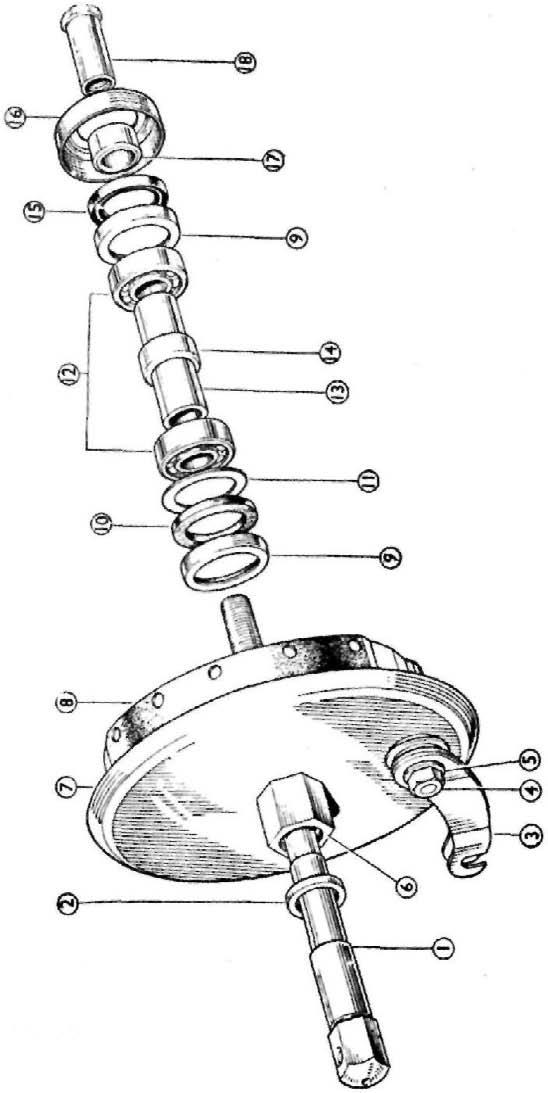
FIG 30
1 2
3 4 5
6
7 8 Key to FIG 30 1960-62 front hub assembly
Spindle, front wheel Washer, front wheel spindle (350 c.c. only) Lever, brake shoe expander Nut, brake shoe expander lever Washer, brake shoe expander lever Spacer, hexagon, front cover plate Cover, front brake plate Brake shoes, pair 9 10 11 12 13 14 15 16 17 18 Enclosure cup, oil seal Seal, felt, for bearing Washer, bearing felt seal Bearing, for hub Spacing tube, bearing Pressing, spacing tube Seal, rubber, for bearing Enclosure cap Spacer, front spindle Nut, front spindle
will be concentric with the brake drum, with immediate efficiency, providing the brake drum is not badly scored.
The brake drums are not detachable.
If braking efficiency is impaired by reason of over greasing the wheel hub, the brake shoes should be de-greased and not treated with petrol or paraffin, which only tends to make the grease more fluid.
Contrary to general belief, a smooth surface on the brake linings gives the best braking. Centralizing the brake shoes. If the rear wheel and the brake cover plate has been disturbed, when the wheel is refitted leave the spindle nut 043303 and lock nut 043305 slightly loose.
Press hard on the rear brake pedal, tighten the lock nut whilst pressure is maintained.
The fact of opening out the spindle hole in the cover plate to the extent of Q" will ensure centralization. Brake squeal. Check linings and drum for dust from linings. Centralize brake shoes or fit new type rear brake expander lever 043419, which will also improve braking efficiency. Wheel bearings (Lightweight Models). Two journal bearings at each end of the hub are a press in fit. The bearings are greased when assembled. The bearings should be cleaned and re-greased every 4,500-5,000 miles. Use grease of the anti-centrifuge type for these bearings.
If wear develops on the right-hand front wheel bearing, entry of water is the cause. Fit the new water excluder 043420 to shroud the bearing.
Discard cover 043282 and spacer 043358. Wheelbearings (250 c.c. Scrambler). Taper roller bearings similar to those used on the Heavyweight Models are fitted to both wheels. The outer cups are pressed into the hubs.
These bearings rarely need adjustment, providing grease is applied via the nipples on the hub, say every 1,000 miles.
For service details see Heavyweight Models. Speedometer gear box lubrication. Where a grease nipple is not fitted, periodical lubrication is not necessary as the drive parts are made from self-lubrication material. A little oil on the seal is beneficial when the drive is removed from the wheel.