11 minute read
Dynamo


borundum stone or very fine emery cloth and afterwards wiped with a cloth moistened with petrol. Adjustment of contact breaker (Magneto type SR-1). If and when adjustment is necessary slacken the two screws securing the fixed contact plate and adjust the position of the plate until the gap, when the contacts are fully opened, is set to the thickness of the gauge. The correct gap should be .010" to .012".
DYNAMO
A LUCAS type E3-N dynamo is fitted. It is anti-clockwise in rotation. The cutting in speed is 1250-1500 r.p.m. at 7 volts and at 1,850 to 2,200 r.p.m. is gives an output of 5 amps at 7 volts. The replacement part number is 20028A. The negative brush is insulated and the positive brush is earthed. The two exterior terminals are marked "D" and "F" indicating the respective terminals for the Positive and Field wires that lead to similarly marked terminals on the Regulator Unit. Inspect commutator and brush gear every 5,000 to 6,000 miles. (Maker's Recommendation.)
Remove the cover band to inspect commutator and brush gear,
The brushes are held in contact with the commutator by means of springs. Move each brush, see they are free to slide in their holders, if dirty, or if sticking, remove and clean with a cloth moistened with petrol. Take care to replace brushes in their original positions, otherwise they will not “bed” properly on the commutator.
If, after long service, the brushes have become worn to such an extent that the brush flexible wire is exposed on the running face, or if the brushes do not make good contact with the commutator, they must be replaced by genuine LUCAS brushes.
The commutator must be free from any trace of oil or dirt and should have a highly polished appearance. Clean a dirty, or blackened, commutator by pressing a fine dry cloth against it while the engine is slowly turned over by means of the kick-starter. (It is an advantage to remove the sparking plug before doing this.) If the commutator is very dirty, moisten the cloth with petrol,
At every 10,000 miles, the complete dynamo should be handed to a Lucas Service Station for dismantling, replacement of worn parts, cleaning and lubrication.
Electrical breakdown of the dynamo is most unusual and therefore before assuming this unit is defective, it should be tested as follows:
Check that the dynamo, regulator and battery are correctly connected. Test dynamo in position by: (a) Remove the two wires from the dynamo terminals and connect the two terminals with a short length of wire. (b) Start the engine and set to run at normal idling speed. (c) Connect the negative lead of a moving coil voltmeter (calibrated not less than 0 to 10 volts) to either of the two dynamo terminals and connect the positive lead to a good earth point on the dynamo or engine. (d) Gradually increase the engine speed, when the voltmeter reading should rapidly rise and without fluctuation. 114
Do not allow the voltmeter reading to rise above 10 volts.
Do not race the engine in an attempt to increase the voltage. It is sufficient to run up the engine to a speed of 1,000 r.p.m.
If the above reading is obtained the dynamo is in order.
If there is no reading, check the brush gear.
If there is a low reading of approximately ½ volt, the field winding may be at fault.
If there is a low reading approximately 1½ to 2 volts, the armature winding may be at fault.
If the tests, mentioned above clearly indicate the dynamo is not charging, it is then desirable to remove the dynamo from the machine in order to make further tests and repairs or replacements. To remove the dynamo (before 1957).
Remove the left side foot rest arm.
Place a tray under primary chaincase to catch the oil.
Remove chaincase band binding screw and remove metal band and also endless rubber band.
Remove nut and washer in centre of chaincase when outer half can be taken away.
Remove spring circlip, locking plate and nut securing dynamo sprocket and withdraw sprocket with a suitable tool (Use spanner 017254 to hold sprocket while nut is being slackened, this relieves the dynamo shaft of all bending strain.)
Detach dynamo cables and loosen dynamo clamping bolt to fullest extent.
Twist dynamo by hand until the locating strip on its body is in line with the keyway cutaway in the rear engine plate housing the dynamo, in which position same can be withdrawn tilting upwards to clear gear box while doing so.
To re-fit the dynamo, reverse the foregoing taking care to accurately locate the dynamo sprocket key when applying the sprocket. See separate instructions for correct dynamo chain adjustment and re-fitting outer half of chaincase. Ensure that dynamo sprocket securing nut is well tightened before refitting locking plate and retaining circlip.
A.V.C. UNIT
Although the voltage regulator and the cut-out are combined structually, they are electrically separate.
The regulator is set to maintain a pre-determined generator voltage at all speeds and regulates the output of the dynamo to the battery according to the state of charge of the battery. The charge rate is at its maximum when the battery is discharged, automatically tapering off to a minimum as the battery becomes charged and its voltage rises.
Normally, during day-time running, when the battery is in good condition, the dynamo gives only a trickle charge, so that the ammeter reading will seldom exceed 1 to 2 amperes, i.e. half to one division on scale. The cut-out is an automatic switch which is connected between the dynamo and the battery. When the engine is running fast enough to cause the voltage of the dynamo to exceed that of the battery the cut-out allows the 115
battery to be charged by the dynamo. On the other hand, when the engine speed is low, or the engine is stationary, the cut-out disconnects the battery from the dynamo, thereby preventing current flowing back from the battery to the dynamo, a proceeding that would soon cause the battery to become completely discharged.
The regulator and cut-out are accurately set during manufacture, If, under normal running, conditions, it is found that the battery is continually in a low state of charge, or is being constantly over-charged, then the regulator setting should be checked by a qualified electrician and, if necessary, reset. Whenever possible, this should be carried out by a LucasService Depot or Agent.
The A.V.C. Unit is retained by two bolts with self-locking nuts. The self locking nature of the nuts prevents subsequent slacking off. The four terminals of the A.V.C. Unit are plainly marked by the letters F.A.D.E. Wires from F and D go to similarly marked terminals on the dynamo. The A terminal is connected to one of the ammeter terminals and the E terminal is “earthed”.
We specially warn against unskilled meddling with the settings of the regulator and the cut-out contacts.
Later machines may be fitted with a new A.V.C. Unit type RB-107, but the foregoing notes will still apply with Che exception of terminal grouping which will be F.A.E.D. To remove control box (after 1957). The A.V.C. unit is held in sponge rubber and housed in a partition at the rear top corner of the tool box. To remove it, open the box lid, grasp the unit between the fingers and thumb of one hand, and gently and firmly pull it out. Re-fit with cover outwards.
The four terminals of the control box are plainly marked by the letters D.E.A.F. Wires from F and D go to similarly marked terminals on the dynamo. The A terminal is connected to one of the ammeter terminals and the E terminal is 'earthed'. Battery—All Models (MLZ9E). A lead-acid battery Lucas type is used on all models.
The voltage is 6, the capacity is 12 ampere hours, at the 10 hour rate.
Machines are issued with dry charged batteries, the acid is filled by the dealer.
All models have the POSITIVE battery terminal connected to 'EARTH'.
To remove the head lamp rim, release the screw retaining the lamp rim with one hand and support the light unit with the other.
The light unit can then be taken off the lamp. To refit. Engage bottom tag on lamp rim with the small slit in the shell and gently force the top of the rim back into the shell, after which retighten the retaining screw on the top of the lamp body.
The main bulb is secured by a bayonet fixing holder which is removed by turning anti-clockwise.
The pilot bulb is a plug-in or push fit.
The headlamp rim is detachable from the light unit by removing six spring clips.
Main bulb
Home Models … … Lucas No. 373 6-volt 30/24 watt prefocus (left hand dip).
French Export Models … Lucas No. 379 6-volt 36/36 watt 3-pin duplo (vertical dip). Parking Bulb … … … Lucas No. 988 3-watt M.C.C. Setting. The headlamp should be set so that when the machine is carrying its normal load the driving beam is projected straight ahead and is parallel with the road surfaceDipper switch. Every 5,000 miles the moving parts of the dipper switch should be lubricated with thin machine oil. Headlamp (Alternator Models). A separate ignition switch is incorporated in the right side of the headlamp body. Lucas stop tail lamp (Model 564). The correct size of bulb to be used in rear lamps' is based on the cubic capacity of the engine. The replacement bulb for this lamp is Lucas No. 384, 6-volt, 6/18 watt. Small bayonet cap. Lucas horn (Model HF 1441). Horns are pre-set to give their best performance and, in general, no further adjustment is necessary.
If the horn becomes uncertain in its action, giving only a choking sound, or does not vibrate, it does not follow that the horn has broken down— the trouble may be due to a discharged battery, a loose connection, or short-circuit in the wiring of the horn.
In particular ascertain that the horn-push bracket is in good electrical contact with the handlebars.
It is also possible that the performance of a horn may be upset by its mounting becoming loose,
ALTERNATOR Model RM15
The following data applies to three versions of Model RM15, namely, 540, 210, 18, fitted to magneto ignition machines, 047, 534, fitted to coil ignition machines, and 540, 210, 05, fitted to two-way radio equipped machines. Test equipment required. (1) First-grade moving coil a.c. voltmeter. 0-20 volts. (2) First-grade moving coil d.c. ammeter. 0-25 amps. (3) One ohm load resistor (capable of carrying 20 amperes without overheating). Test No. 1. For this test, the battery must be in good condition and more than half charged. (1) Connect the d.c. ammeter between the battery negative terminal and the battery main cable. (2) Start the engine and set it to run at approximately 3,000 r.p.m. (3) Observe the ammeter readings in each of the positions of the lighting switch.
The figures given in the following table are the minimum acceptable battery input currents. If the readings obtained are lower than the figures quoted, proceed to Test No. 2.
Minimum acceptable battery charging currents.
Off … Parking Head … 2.75 2.0 2.0 2.5 1.5 2.5 Boost switch Boost switch Open Closed 4.0 9.0 2.5 7.0 3.5 3.5
Minimum acceptable voltage readings,
Voltmeter and Resistor connected between Despatch number of unit. 540, 210, 18 047, 534 540, 210, 05
White-with-Green and Green-with-Black cables
White-with-Green and Green-with-Yellow cables
White-with-Green and Green-with-Black (with Green-with-Yellow connected to Green-with-Black) 4.0
6.5
8.5 4.0
6.5
9.0 9.5
13.0
15.5
Each cable in turn and earth Zero Zero Zero
Unsatisfactory readings can be due to defective wiring or connections.
Ensure that all snap-connector joints and earth connections are in good condition before proceeding to Test. No, 2.
If considered necessary, check the rectifier by substitution. (1) Disconnect the three alternator output cables. (2) Start the engine and set to run at approximately 3,000 r.p.m, (3) Connect the one ohm load resistance in parallel with the ax. voltmeter and check the voltage between the alternator output cables. (4) Conclusions to be drawn from results of above tests:
Demagnetised rotor magnets indicated by all readings being low.
Short-circuited coil indicated by individual reading being low.
Earthed coil or coils indicated by voltage reading between any output cable and earth.
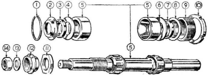
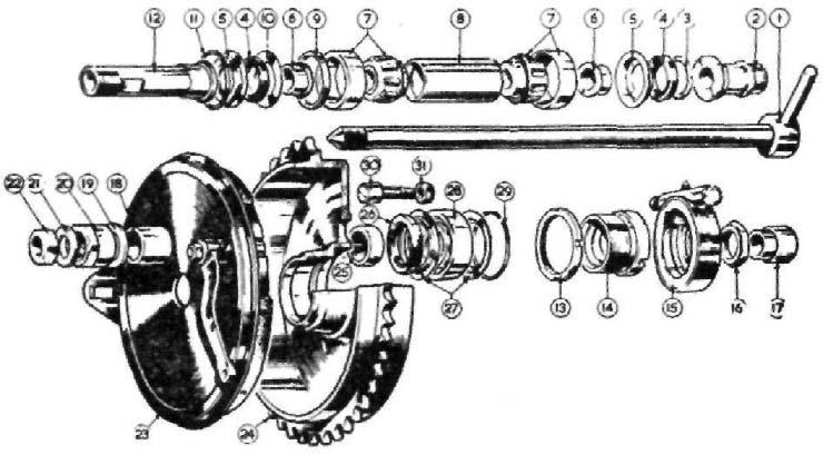
Alternator. Model RM15, with rotor, withdrawn (REC 728).
CONDENSER CHECK
When investigating a misfire, and where the condenser is suspect, the use of an external condenser will prove if this component is defective,
Use a sound condenser with two crocodile clips attached.
Attach one clip to the low tension terminal on the distributor, the other to a convenient earth position.
A short test, by running the engine, will indicate if the condenser is defective.
In the case of Single Cylinder Models, remove contact breaker cover, fit one clip to terminal for contact breaker pivot post, the other to earth.
CHECKING THE RECTIFIER
If a spare rectifier known to be in good condition is available, the simplest check is that of substitution. (In this connection, Lucas rectifier 47132 is used with alternators 540, 210, 18 and 047, 534, while rectifier 47142 is used in conjunction with alternator 540, 210, 05.)
When a satisfactory substitute is not available, the rectifier is best checked by removing it from the machine and bench testing it.