6 minute read
Wipac alternator


Air leaks either at junction of carburetter and inlet manifold, or by reason of badly worn inlet valve stems or guides.
Faulty engine valve seatings.
Sparking plug faulty, or its points set too closely.
Ignition advanced too much.
Contact breaker points dirty, pitted, loose or set too closely.
High-tension wire defective.
Pilot jet not operating correctly. Partially choked or incorrect air supply.
Rockers adjusted too closely. Heavy petrol consumption may be due to:
Late ignition setting.
Bad air leaks. Probably at carburetter or manifold joints.
Weakened valve springs.
Leaky float (causing flooding).
Taper needle extension insufficient.
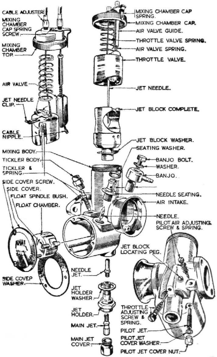
Poor compression, due to worn piston rings or defective valve seatings. (Test compression with throttle wide open.) Carburetter flooding. If the carburetter is flooding, the float spindle bush (Fig. 31) may be pinched between the float swivel and the float chamber cap.
Reduce slightly the width of the tube or renew the gasket for the cover.
Exercise care to avoid over tightening the pilot jet which can deform its seating in the mixing chamber. A defective jet block fibre washer will allow fuel to leak across the choke. Notes on Carburation. The main jet originally fitted is deemed to be the most suitable. There should be no necessity to alter the main jet size without good reason, Le. by. fitting an air filter, running with an open exhaust pipe system or at specified altitudes.
Riders with considerable experience can, after driving at full throttle for at least a third of a mile decide, after 'reading' the sparking plug if the main jet size is suitable or otherwise.
Without such experience it is preferable to drive at full throttle and close the air lever ¼". If the engine speed increases,. the main jet is small. Conversely, if the engine speed decreases, the main jet is large.
Jet alterations should he made in stages of 10 c.c. increase in jet size, viz. size 200 to 210.
WIPAC ALTERNATOR
The series 114 Alternator consists of a six pole Stator ring 5" in diameter with six coils and a six pole permanent magnet rotor. There are three main leads coloured white, light green and Orange. Three coils are connected in series to white and light green, the other three coils are connected in series to white and orange. The output from these coils is a.c. converted to d.c. by means of a bridge-connected metal rectifier. The output of the alternator is controlled through the switch on the headlamp and connects three or six coils according to its position. Emergency starting. The emergency position is intended for starting when the battery is discharged. This position is marked 'EMG' on the ignition switch.
In this position the two groups of alternator coils are connected in parallel, and if the lights switch is in the 'OFF' position the full output of the alternator goes into the battery. This will raise the voltage of a discharged battery to a level sufficient to start the engine. In the EMG position the charge rate is high—the engine should not be run in EMG too long. The boost charge thus provided may be used to restore a discharged battery. Switch over to IGN after ten minutes. Rotor demagnetised. Although the WIPAC Rotor is robustly built and holding a very high magnetic charge, it can become demagnetised if the machine is run with battery connections reversed, or if the rectifier breaks down. A demagnetised rotor should be returned to WIPAC for satisfactory remagnetisation. Testing. Testing of component parts can be carried out if the following instruments are available: 0-12 d.c. Volt Meter. 0-15 a.c. Volt Meter. 1 ohm Resistor (capable of carrying 8 amps.). 10-0-10 d.c. Ammeter.
High grade and accurate moving coil instruments must be used. The 1 ohm, resistor must also be accurate, otherwise correct readings cannot be obtained. Engine speed when testing should be in the region of 2,500 r.p.m. Tests should not be attempted at speeds below 2,000 r.p.m. A few revs. above or below 2,500 will not affect the readings of an alternator in good condition. Charge rate test: (1) First check the battery voltage which, if fully discharged, should he substituted for one that is in good condition. (2) Disconnect the brown negative lead from the double connector, (3) Connect the d.c. ammeter in series with the battery wire and the double connector. (4) Run the engine at 3,000 r.p.m., the minimum permissible readings are shown in the following table:—
Ignition switch Lights switch Minimum charge rate
Ignition on Ignition on Ignition on Emergency on Off Low High Off 1.0a 13a 1.0a 6.0a
The rate of engine speed and condition of the battery will affect the charge rate recorded. The figures shown in the table in comparison with the recorded figures indicate if the system is functioning correctly. NOTE —If the charge rate is down with lights on HIGH check the main bulb wattage. Low or no charge rate test. Check the alternator output by: (1) Disconnect the white, orange and light green wires from the four
way connector. If a maroon colour lead is also used, leave this in position. (2) Using the a.c. voltmeter with the one ohm. resistor across the terminals (parallel) join one wire from the voltmeter to the white wire, the other meter wire to the orange wire. Run the engine at a speed equivalent to 30 m.p h. in top gear, the voltage reading should be between 6.2 and 6.8 volts.
Transfer the meter wire from the orange wire to the light green and repeat the test. A low reading on one of these tests indicates a fault in the coils. A low reading on both tests can be due to a partially demagnetised rotor.
If no reading is shown on both tests, the alternator is defective (see test 3). (3) A short circuit to earth on one or more coils will affect the a.c. voltage output.
To check, with the front chain case in position, use the d.c. voltmeter in series with a battery in good condition. Connect the wire from the meter to the white wire, the battery wire to a good and convenient earth on the engine. If a reading is shown on the meter, one or both coils are shorting to EARTH. NOTE —The white wire is common to all coils.
Remove the outer portion of the chain case, check the alternator wires for damaged insulation, also coil connections before discarding the alternator,
When the fault is located, repeat the tests previously described. Rectifier tests. Before testing, verify the earth connection is clean and secure. Check also the wires attached to the rectifier for loose connections. Take out the white, green.and brown wires from the rectifier,
For this test use a 6 volt battery connected to a 3 watt bulb and holder.
Test in the following sequence: Positive wire to Light Green White ” ” ” } Bulb earthed. Bulb lights. Rectifier O.K. ” ” ” ” ” ” Brown Brown } Bulb on Green. No light. Bulb on White. No light. Rectifier faulty.
Reverse the battery connections with: Negative wire to Light Green White ” ” ” } Bulb earthed. No light. Rectifier O.K. ” ” ” ” ” ” Brown Brown } Bulb on Green. Bulb lights. Bulb on White. Rectifier faulty. NOTE —The common cause of rectifier trouble is invariably due to reversed battery connections, which can also demagnetise the rotor, if the engine is run with these connections reversed. The battery positive terminal is connected to EARTH (translucent), the negative is the feed line (brown). Ignition and lighting switches. Both switches in the head lamp are