5 minute read
Wheel bearings

Removing the rear mudguard. Remove ¼" bolt securing rear guard to frame loop.
Remove c" stud fixing bottom front of the guard to the frame lug.
Remove bolt (3) and spacer, and chain guard.
Remove bolt fixing rear chain guard at front. To remove the rear loop. Remove stud uniting rear loop to seat lug.
Remove nut for stud on right side of rear loop.
Remove this stud with brake pedal attached, take away the rear loop.
Remove screw for plate in swinging arm.
Release the two cotter pin nuts which locate the bearing tube. Push out the bearing tube. Swinging arm bushes. The two flanged bushes are housed in steel sleeves which are not supplied separately. The bushes are of the oilite type, but provision is made for lubrication via the centre plate screw (use heavy duty oil). If lateral movement develops at the wheel end this could be due to end float between the arm and the frame lug, particularly after long mileage, with a sidecar attached. Taking up side play. When it has been ascertained that end play is manifest, it is extremely difficult to absorb this movement by moving the bushes with the arm assembled in the frame, even with a sturdy support on one side of the arm. Whilst the bush in the opposite end is drifted in, there is always a certain amount of spring in the two extremities of the arm. It is therefore preferable to take the swinging arm away from the frame.
To decide if the bearing tube or the bushes are worn, the spindle diameter is .9995"/.9990", the bush diameter in situ is 1.001". At the factory a pilot reamer 1" diameter is used for these two bushes, for correct alignment.
WHEEL BEARINGS Heavyweight Models
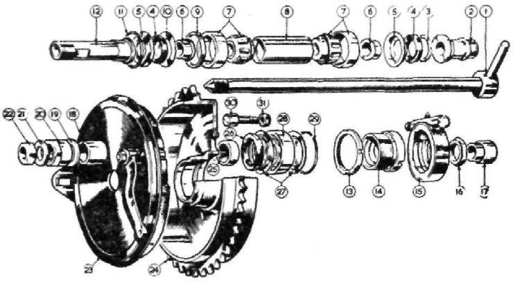
The break down of the front wheel bearings: is shown in Fig. 26. It is vitally important to avoid tightly adjusting bearings of the taper roller type, as a crushing action takes place, the rollers will be damaged beyond further use. Should excessive movement suddenly develop, the bearing should be dismantled for inspection, for with correct adjustment and constant lubrication, these bearings will last in definitely. To dismantle the bearing. Remove the front wheel.
Remove nut securing brake cover plate (12).
Remove locating nut (11) and washer.
Remove locking ring (10) and cover disc.
Remove adjusting ring (9).
Press out the spindle from the threaded end which will push out items 6-7-8 and bearing ring 5.
The bearing ring will remain in the left side of the hub. To extract the bearing ring. Press in the washer (4) sufficiently far enough to permit the circlip (1) to be extracted.
Use a piece of steel tubing passed through the hub and drift out the bearing sleeve, which will also eject the washer (4), oil seal (3) and collar (2).
FIG 26 Front wheel bearings
1 Circlip 2 Oil seal cup 3 Oil seal 4 Washer retaining seal 5 Wheel spindle complete 6 Washer retaining seal 7 Oil seal 8 Oil seal cup 9 Adjusting ring 10 Adjusting ring locknut 11 Nut locating brake coverplate 12 Nut securing brake coverplate 13 Spindle end washer 14 Spindle end nut
Avoid using heavy hammer blows when taking the spindle out, as this action can cause indentations in the bearing sleeve. Adjusting the front wheel bearing. Release the locking ring (10), screw in the adjusting ring (9) until the bearing is devoid of end movement, unscrew the adjusting ring half a turn only, give the opposite end of the spindle a light blow to move the bearing ring away from the bearing.
Position the cover disc and firmly retighten the lock ring.
There should be approximately .002" side rock at the wheel rim if the adjustment is correct. The friction of the oil seals can create a false impression that the bearing is tight. Dismantling rear wheel bearing (Fig. 28). Before removing the rear wheel, release the speedo drive fixing nut (16), disconnect speedo cable and take out the wheel.
Remove the nut (16) and speedo gear box, release the lock ring (13).
Remove adjuster sleeve (14) and speedo gear box sleeve (2), and cover disc.
Remove the washer (3), oil seal (4) and oil seal cup (5); also distance piece (6).
Turn to the brake side of the hub, when with the use of a short steel rod or tubing, with an external diameter of J" drift out the hub internals, leaving the bearing ring (7) in situ. To remove the bearing ring. Press inwards the steel cup washers (5) to permit extraction of the circlip (11), take out the cup washer, oil seal and spacer (6). Drift out the bearing ring with a length of steel tubing. NOTE—When refitting the circlip press back the bearing ring. See 'Wheel bearing adjustment'.
Brake drum bearing Fig. 28. With the brake drum away from the frame. to dismantle:
Remove dummy spindle (12).
Remove circlip (11) and cup for oil seal (5).
Remove bearing by drifting out, with second cup.
Remove oil seal (4) and distance piece (6).
Refit the oil seal with metal backing towards the inside of brake drum. Use a little anti-centrifuge grease for the bearing.
1 2 3 4 5 6 7 8 9 10 11 12
13 14 15
16 17 18 19 20
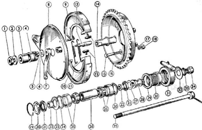
FIG 27 Non-quick-detachable wheel assembly Nut for wheel solid spindle 21 Oil seal, for bearing Washer, for wheel spindle nut 22 Spacer, on spindle, for oil seal Spacer, for wheel spindle nut 23 Ring, retaining hub bearing, large Spacer, for cover plate, outer 24 Spacer, between bearing and oil Nut, for expander lever seal Washer, for expander lever nut 25 Bearing, roller Lever, expander 26 Spacer, between bearings Plate, cover 27 Ring, retaining hub bearing, Shoes, brake, with linings small Linings, for brake shoes. 28 Spacer, on spindle, for Spring, for brake shoes speedometer gearbox Pin thrust, adjusting brake 29 Nut, lock, bearing adjusting ring shoes 30 Ring, adjusting bearing Expander, for brake shoes 31 Speedometer gearbox Spacer, for cover plate, inner 32 Washer, outside, speedometer Bolt, retaining, sprocket to gearbox hub shell 33 Nut, locking, speedometer Sprocket and brake drum gearbox Washer, sprocket retaining bolt 34 Spacer, on spindle, speedometer Nut, sprocket retaining bolt gearbox side Ring, spring, locating bearing 35 Spindle, rear wheel solid Cup, for bearing oil seal 89