38 minute read
Engine overhaul


.016 inch so that the tappets may be well clear of the quietening curves of the camshafts.
The timing gears are marked to facilitate their replacement.
To re-set the valve timing, by using the marks on the gears, proceed as follows;—
Turn over, the engine till the mark on the small timing pinion is in line with the centre of the inlet (rear) camshaft bush. Insert the inlet camshaft so that the No. 2 or No. 3 mark on it is in mesh with the mark on the small timing pinion, according to model.
Rotate the engine in a forward direction till the mark on the small timing pinion is in line with the centre of the exhaust (front) camshaft bush.
Insert the exhaust camshaft so that the No. 1 mark on it is in mesh with the mark on the small timing pinion.
Trials Models
Inlet opens 26° before top dead centre.
Inlet closes 53° after bottom dead centre.
Exhaust opens 64° before bottom dead centre.
Exhaust closes 25° after top dead centre, taken with 0.016" tappet clearance and with the valve 0.001" off its seat.
Removing the engine from frame. The engine with gear box can be removed as a complete unit—removing the gear box first makes handling easier. Disconnect battery wires as a precaution against fire.
Start by stripping down as described for "removing the cylinder and piston".
Remove drain plug from front chain case to drain oil.
Remove near side footrest and engine plate cover—two screws.
Remove four snap connectors on alternator cables.
Remove six chain case screws and inspection cap.
Remove chain case cover—with care to allow the cables to come through the rear portion of the case.
Remove three clutch springs—take away the pressure plate.
Remove gear box mainshaft nut securing clutch.
Remove nut fixing rotor on engine shaft—use a close fitting ring spanner.
When a duplex front chain is used remove the clutch and engine sprocket simultaneously as the chain is “endless”. When a single chain is used take out the connecting link.
Remove fairing for timing cover 042053/4, pull out the contact breaker wire. Removing the gear box.
Remove connecting link from rear chain, take out the clutch cable.
Remove kickstarter crank and gear pedal.
Remove gear box adjuster bolt 042394 also all nuts fixing right side
rear engine plate with distance pieces behind it. Release the two clamp nuts then take away the plate and the gear box. Take out the engine by:
Removing five studs passing through the crankcase and frame.
Raise the rear end of the crankcase—pull it back and out of the frame.
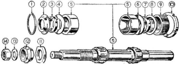
If difficulty exists, take the machine off the central stand the frame will open and let the engine come out. Dismantling the engine. Before dismantling, study the exploded view of the engine. Special tools required. (1) Extractor bolt for automatic ignition device 042247. (2) Small timing pinion extractor 043332. (3) Clutch withdrawal tool 040449—only required when clutch is a tight fit on the shaft. With engine removed from frame.
Remove drain plugs from crankcase and oil reservoir.
Remove contact breaker base plate—use tool 042247.
Remove four bolts for cam housing—gently tap it to remove,
Remove nine bolts for reservoir, it will then come away.
Remove small timing pinion nut RIGHT HAND THREAD then strip down the timing gear in the following order. (1) Camshaft. (2) Camshaft distance piece—wide, (3) Camshaft follower exhaust. (4) Camshaft distance piece—narrow. (5) Camshaft follower, inlet. Warning. An attempt to separate the crankcase halves, without first removing the oil pump plunger 042178 will result in serious damage, by making the crankcase beyond further use.
Remove oil pump guide pin 010079 and sleeve 010138.
Remove screwed plug and 'O' ring 042178,
Remove oil pump plunger 042104—insert a piece of rod in the spindle hole to extract it.
Remove felt filter cap 042058, take out the filter.
Remove six crankcase bolts 042035, one bolt 042036, also stud 016103 —the timing case half can now be separated from drive side.
Remove the breather stator fixing tube at the rear of the crankcase. On engines after number 8979 the stator is fixed by a bolt below the drive side bearings.
The crankcase must be heated to relieve the interference fit of the bearings in the crankcase—not above 200 centigrade, when the crankcase will come away leaving the ball bearing in the case.
Re-heat the case—use a drift to drive out the ball bearing,
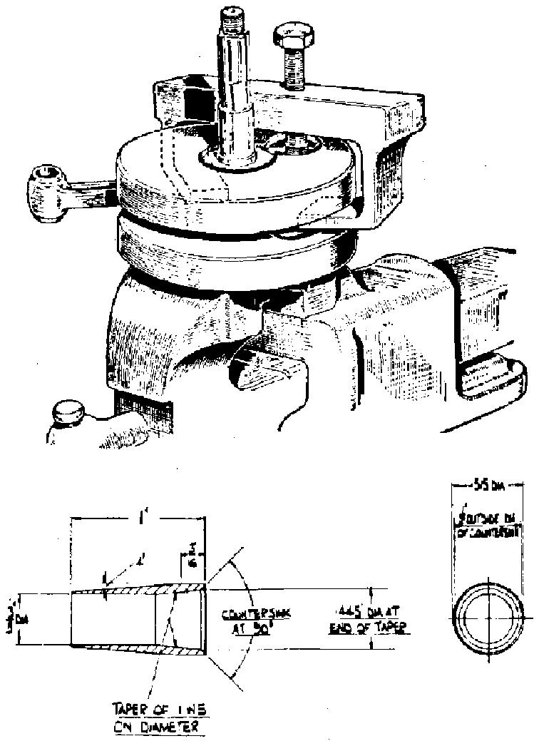
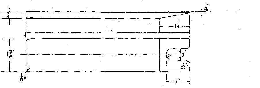
Take off the breather stator from the shaft, watch for the key which must be removed before taking off the inner bearing. Dismantling the flywheels. A flywheel separating tool is shown in Fig. 7, With one crank pin nut removed place the tool over the flywheels as shown—position the draw bolt. By screwing in the bolt the flywheel will come away from the crank pin.
Flywheel tool
FIG 7 Removing the flywheel shafts. Both shafts are a force fit in the flywheels and are removed by using an arbour press. Removing the timing side bush. Support the case with a suitable piece of tubing and press out the bush from inside the case—the retaining pin will come out with the bush. Removing the cam wheel bush 042101 in the cover. First take out the oil seal 042183—press out the bush from inside the cover, warming the cover will make it easier to remove.
When re fitting the bush locate the slot in it at 12 o'clock. Replacing the oil seal 042183. The oil seal is refitted with the metal backing facing outwards, a simple tool to avoid damage to the seal when the cover is fitted is shown in Fig. 7.
Assembling the flywheels. The importance of using an arbour press to assemble the flywheels cannot be too highly stressed. To rely on tightening the crank pin nuts will result in a broken crank pin, due to the flywheels flexing when the engine is under load. It is for this reason that after fitting the crank pin, both flywheels must be forced together under a press, so that the shoulder of the crank pin is hard against the flywheel. It is after this operation that the nuts are tightened. The torque spanner setting when cast iron flywheels are used is 140 ft. lbs. With engines that have steel flywheels the torque setting is 190 ft. lbs.
If, after assembling the flywheels, the connecting rod is not free to rotate, this could be due to one or both drive shafts moving inwards and rubbing against the connecting rod. Drive home the shaft that is affected, The flywheels should run true, in centres, to a limit of .001" to .002" and no more, Refitting the timing side bush. Locate and press in the bush, then fit the locating pin, designed to prevent the bush moving. Replacement bushes are sized to allow for contraction when in the crankcase. If the shaft will not enter, or is a tight fit, ream the bush to .8755" to .8750". The bush should be flush with the inside of the crankcase. Refitting the drive side bearings. The crankcase should be gently heated to fit the bearings, assemble in the following order:
Fit the bearing 012542—nearest to the engine sprocket.
Fit the stator 043036—locate with the tube, or bolt whichever is fitted.
Fit the bearing ring in the crankcase—“peen” the ring in three places.
Fit the centre member for the bearing on the drive shaft, fit the key for the rotor 041021—then fit the rotor to engage with the key, apply oil to it.
Insert flywheels into the drive side crankcase.
Apply jointing compound—“Wellseal”—to crankcase joint, verify all oilways in the timing side crankcase are clear, then fit the case to the drive side half.
Pass the seven bolts through the crankcase and tighten,
Check the small bolt for the oil pump plunger 042046—the tip may have broken away. When renewing the “O” ring—fit this to the widest of the two rings. Insert the plug 042044 chamfered end first and locate it with the pin 042046 mentioned above. Fitting the oil pump plunger. Apply some clean oil, insert the plunger into the crankcase to a. depth of l n" from the screwed plug face. Check the end of the guide pin (which engages with the annular slot in the plunger) for wear at the top end. A small flat worn at this end will curtail, or cut off the oil supply to the rocker gear and a new pin must be fitted. Using extreme care, screw in the sleeve with the guide pin 010079—the reduced end goes inside the sleeve—and make sure that the guide pin engages with the annular groove in the plunger. Do not use force, move the plunger to engage the pin if necessary, use a spanner only when the sleeve is fully home. Failure to observe these precautions can ruin the plunger beyond further use.
Fit the housing plug 042045 with its washer. Firmly tighten as an air leak at this point will affect the oiling system.
Fitting the timing gear. Assemble as detailed in para VALVE TIMING. Oil filters. Before fitting ensure that the fabric filter is undamaged and is clean.
350 c.c. and 500 c.c. Heavyweight Models
Removing the engine from frame. If the engine has to be removed for dismantling, commence by following the instructions given for removing the cylinder and piston. To facilitate crankcase assembly removal then:
Disconnect two wires from the battery.
Disconnect both oil pipes (watch spanner manipulation at crankcase end) and drain oil tank.
Lever the oil pipes off (tank end) with a screwdriver or a piece of wood.
Disconnect four snap connectors for alternator wires and contact breaker cable, lift off the engine plate cover to expose connectors.
Remove rocker box oil pipe from crankcase. Remove timing cover 027093.
Remove central nut for front chaincase, place a receptacle under chaincase to catch oil.
Remove outer portion, with extreme care, feeding the alternator wires through the rear portion of chaincase.
Remove nuts securing rotor to engine shaft.
Remove clutch springs and clutch pressure plate.
Remove nut on gearbox mainshaft securing clutch. An 'easy to make tool' to prevent the mainshaft moving is shown is Fig. 8.
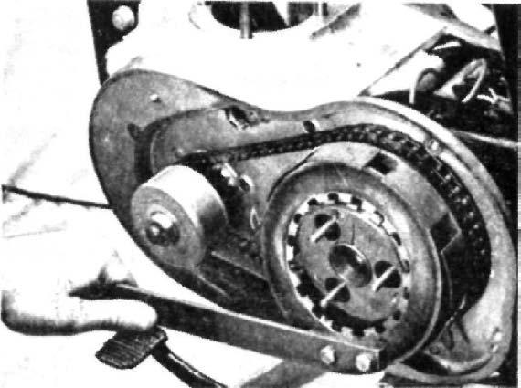
FIG 8
Remove front chain and take off clutch assembly (use clutch withdrawal tool 040449).
Remove rotor, engine Sprocket, watch for distance piece behind it.
Remove three countersunk screws fixing rear portion of chaincase to engine.
Remove crankcase breather pipe.
Remove front engine plate bolts and take away engine plate.
Remove both footrest arms,
Remove three bolts passing, through rear engine plate and crankcase.
Release the top and bottom gearbox fixing nuts a few turns,
Move the crankcase assembly forward, Lift and take it out of the frame, NOTE—If a magneto is fitted, follow details given for removing Scrambler type engine. Warning: When the engine has to be re-installed, connect the two oil pipes at the crankcase end first.
Screw home as far as possible the two nipple nuts by finger application, to avoid the risk of cross threading. Finally tighten without undue force with suitable spanner. Removing tappet guides. Both guides are a force fit in the crankcase, the guide with its tappet are removed together from inside the timing chest. It is preferable to effeot this operation with the engine in a dismantled state, with both halves of the crankcase bolted together to avoid distortion and give additional support.
Heat the crankcase in the vicinity of the guides, sufficiently to enable them to be drifted out. Use the same method to refit the tappet and guide. The two dowel pins for the cover can fall out, when the crankcase is heated. When the guide is correctly located, the outside diameter is just flush with the crankcase face. Dismantling the rocker box. The design of the rocker box is basically the same on all single cylinder models. Some Lightweight 250 c.c. models do not use a valve lifter, but a later type rocker box 044034 can be used on this type of engine. Use the following parts for the valve lifter assembly:— Valve lifter lever 013969. Valve lifter spring 044035. Valve lifter screw 000451. Valve lifter washer 000039. Valve lifter lever ring 014523. Valve lifter cable 026254. Valve lifter lever assembly 026239.
The rocker box is supplied with bushes. The existing rockers, etc., can be transferred.
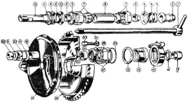
It is best to refer to Fig. 3 to understand the assembly sequence of the parts used in the rocker box. To dismantle, place a box spanner (that will fit the nut 000003) firmly in a vice. Invert the rocker box, place one of the two rocker spindle nuts into the box spanner.
Using an open end spanner, release and remove the rocker axle nut inside the rocker box.
Using a soft drift, tap out the axle, when the inside rocker will drop
off the spindle. The outside rocker with spindle can be pulled out together with the steel sleeve 017292.
Either one or two felt sealing rings used midway between the two rocker axle bushes can be prised out with a sharp pointed tool. As a guide, measure the protrusion of the inner bushes before removal. Removing the rocker bushes. If the rocker box is slightly heated, the rocker bushes can be drifted out without difficulty. Refitting the rocker bushes. It should be explained that the location of the rocker bushes controls the end play between the bushes and the rockers. Re-heat the rocker box and fit one of the inner bushes, chamfered end first. The bush should be to the amount measured before dismantling, which usually is approximately E". With the four bushes assembled and if new ones are used, they should be reamed to s" + .00075" — .00050" in situ. Introduce the felt ring(s) into the groove. A taper mandrel inserted into the felt ring is desirable to compress the felt to enable the steel sleeve to pass through. Put the steel sleeve (with some oil on it) over the rocker spindle with the outside rocker attached, carefully work the assembly through the bushes and felt ring.
Refit the inner rocker and using again the box spanner firmly tighten both nuts. If the rocker assembly is tight to move, a light tap on the outer end of the rocker spindle with a light hammer will move the bush and give a free movement. The end play should just be discernible. If the end play is in excess, take out the spindle assembly and tap outwards one of the bushes. NOTE— The rocker arm valve end should be central with the valve stem. Separating the crankcase. With the crankcase out of the frame start by:
Removing oil pump guide pin and sleeve (6) Fig. 9.
Removing four bolts securing cap for oil pump plunger and pull out the plunger.
Removing bottom and front crankcase bolt.
The crankcase can now be separated, as the small timing pinion will pass through the timing side bush; the pinion can be dealt with later. Separating the flywheels. To do this use the tool and method described for the 250 c.c. Scrambler models. Removing small timing pinion. The nut securing this pinion has a lefthand thread. The pinion is a taper fit on the shaft and usually requires an extractor tool B2151. When using any kind of extractor, apply light pressure on the withdrawal part of the tool, then give the end a sharp blow with a hammer, the shock will dislodge the pinion. A new pinion will absorb backlash and cure timing gear rattle. Removing the drive side bearings. Gently heat the drive side crankcase and drift out both bearings. Check both bearings for roughness caused by pitted race tracks. Renew the bearings at the slightest sign of roughness, the bearing should spin by hand rotation smoothly and quietly. Removing the timing side bush. Support the half crankcase firmly, press out bush from timing cover end, the locating peg will come out with bush. If a new bush is used, ream in situ to 1.125" + .0005" — .0000". Replace locating peg when bush is in position. Camshaft bushes. These rarely wear, do not be misled by waggling the
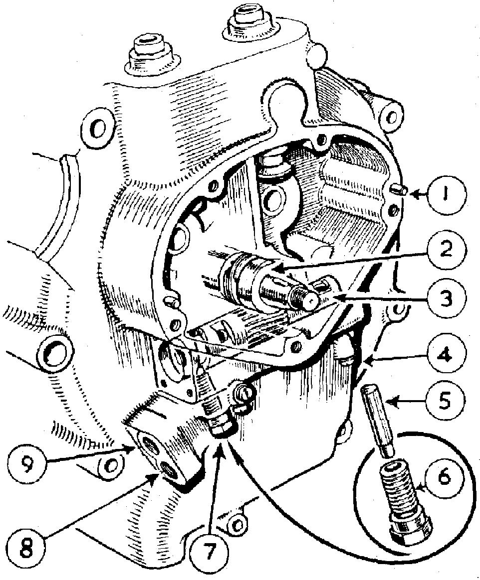
FIG 9
The rotating oil pump plunger is here shown in situ, together with the guide screw which registers in the plunger profiled groove, thereby providing the reciprocating movement.
Key to FIG 9 1 Dowel peg, locating timing gear cover. 2 Timing side flywheel axle with integral gear for driving oil pump plunger. 3 Oil pump plunger. 4 Screw (one or three) with fibre washer, plugging oil passages cast in crankcase. 5 Guide pin, for oil pump plunger. Inserted relieved tip downward as shown. 6 Screwed body to accommodate the oil pump plunger guide pin. 7 Body, with guide pin in position engaged in profiled cam groove of oil pump plunger. 8 Tapped hole, for pipe feeding oil to oil pump. 9 Tapped hole, for pipe returning oil to oil tank. camshaft supported in the back bush only, the bush is short and some movement will be manifest even with a new bush. Press in new bushes from inside the crankcase with oil holes lined up, Both bushes are located flush with the crankcase. When new they should be reamed in situ to ½" + .0005" — .0005". If new bushes are used, assemble the cam-wheels, fit the timing cover tightly and check cam-wheel for end float and free movement. Use a shim washer 016847 to absorb end movement. End play can dislodge the metal cap on timing cover by hydraulic effect. Reassembling the flywheels. If attention to the big end assembly is needed, it is preferable, wherever possible, to use a factory serviced con rod, as the big end liner, also small end bush, is finished ground in situ to ensure concentricity. Alternatively, use a lapping tool A8078 for the new con rod liner after it has been replaced. The degree of interference fit between the liner and the con rod controls the contraction of the liner. Although liners issued as spares are finished ground to a pre-determined size, concentricity cannot be guaranteed, hence the use of a lapping tool in some cases. Removing the flywheel shafts. Both shafts are a press fit in the flywheels. Remove in turn each shaft nut, support the flywheel and press out with an arbour press, or similar equipment. Refitting the shaft. The correct location of both shafts is of vital importance. If the drive shaft is incorrectly located, the alternator output will be adversely affected. Looking at the outside of the flywheel, the shaft should be inserted with the keyway for the rotor pointing forwards (approximately 9 o'clock).
If the timing side shaft is incorrectly located, the oil supply can be curtailed (with damage to the oil pump plunger), also the valve timing will be deranged. Use a pencil and scribe a line on the shank of the shaft dead central with the oil hole. Offer up the shaft with the scribed line central with the oil hole in the flywheel. Tap the end of the shaft to prevent it moving then press firmly home with a suitable press. To check location of shaft, fit the small pinion, the mark on the pinion should be exactly at 12 o'clock.
Fitting the crankpin. If the engine has covered considerable mileage prior to dismantling, and a new crankpin is needed, the roller cage should be replaced also. Metal or abrasive can become embedded in the soft metal used for the cage, which with further use can cause abrasive wear. Verify oil holes in the crankpin are clear and clean before fitting. Scribe a pencil line (as described for timing shaft) on crankpin shank, enter the crankpin with the line central with oil holes in timing side flywheel and tap it home. Press the crankpin into the flywheel until it lightly abuts against the crankpin sleeve. Fit the roller cage and fill with rollers (30) that have been checked for uniformity in diameter.
Apply some engine oil to the con rod liner, also rollers, or a little Molybdenum Disulphide preparation will provide immediate lubrication. Offer up the drive side flywheel, roughly align both wheels with a straight edge placed on the outside diameter of both wheels. Place both wheels under an arbour press and force each flywheel firmly against the crankpin sleeve. Run. down both crankpin nuts evenly (do not tighten one nut at a time).
Finally tighten both nuts with a torque spanner set to 190 ft. lbs. Set both flywheels with shaft to run true to .001" to .002" error. Reassembling the engine. When refitting the driving side bearings heat the crankcase, introduce the bearing 026762 squarely with the housing, then washer 021859 followed by bearing 021872. Use a mandrel or old drive side shaft to line up bearings, The inner member of both bearings should rotate independently to avoid end loading. Move outer bearing to free off.
Remove every trace of jointing compound from the crankcase joints. also the cylinder base faces. Apply some jointing compound of the nonflaking type, such as "Wellseal", to both crankcase faces. Use oil on the crankcase bearings, put both cases together, pass three bolts through the crankcase evenly spaced (as a temporary measure). Set the cylinder base face square and even (the cylinder can be fitted temporarily for this purpose) then firmly tighten the three crankcase bolts. The flywheel should rotate by hand application freely without tight places if the flywheel shafts are running true. Check for end float, which should be .012" minimum between the flywheels and crankcase. Bearing 026762 is a C3 fit. Refitting the oil pump plunger. First renew the paper gaskets on the pump end caps, stick the gaskets to the plates with jointing compound.
Remove burrs or particles of old gasket from crankcase faces. Take up the oil pump plunger, oil it and insert in crankcase. Clean the interior of screwed body (6) Fig. 9, Oil and insert guide pin (5) as illustrated, the pin should revolve freely. Fit the screwed body and pin with extreme care to ensure the guide pin is located in the annular groove in the pump plunger, using the finger to do so. It may be necessary to revolve the flywheels to locate the pin. The screwed body can be finally tightened with a spanner. "Failure to observe these important instructions can ruin the pump gear beyond further use". Now fit the two end caps. Fitting the camshafts. Refer to details on valve timing. Refitting the timing gear cover. If there is evidence of oil in the contact breaker compartment, the oil seal 024287 should be replaced. To prevent
damage to the oil seal during the process of refitting the cover, a guide tool is used. The tool is fitted over the shaft for the cam wheel, with a little oil on it to guide the seal over the shaft. The seal should be fitted in the cover with the metal backing facing outwards, Clean the lace of the cover and stick a new gasket to it. The cover 024016 can now be put back with three screws 000482, Resetting the ignition timing. Fit the automatic timing control (make sure the weights move freely, apply a spot of oil on the pivot pins) and the contact plate, and roughly assemble the timing control. Set the ignition before fitting the cylinder head as the piston travel can be measured more easily.
Follow details for setting ignition timing previously described.
1962 350 c.c. Short Stroke Engine
The general arrangement of the standard and sports versions are similar in respect of engine design. The bottom part of the engine, excluding the flywheels, is similar to the earlier type engine.
Service details given for the 350 c.c. Heavyweight model apply also to this later type engine.
The push rod tunnels are integral with the cylinder, with oil seals in a recess in the cylinder barrel. Scrambler type valve springs are also used for high r.p.m. The compression ration is 8.5:1.
This engine develops considerably more b.h.p. than the earlier type.
A list of parts that differ from the earlier type are tabulated:—
350 c.c. G3-16 028106 R/Box steady bolt 029318 R/Box steady bolt 028100 Head gasket 028596 Push rod assy. 022518 Push rod rubber 028104 Cylinder head 026030 Inlet guide 024519 Exhaust guide 026028 Inlet valve 028105 Exhaust valve 026861 Valve spring 026862 Valve spring 028531 Crankcase assd. 028102 Cylinder base stud 028095 Cylinder barrel 028101 Cylinder base gasket (New Parts) 014044 Valve spring collar inlet and exhaust 014042 Valve spring collet inlet 014039 Valve spring collet exhaust 015422 Rocker box 028123 Carburetter 041014 Carburetter O ring 015875 Carburetter spacer 028107 Piston 028114 Piston ring chrome 028115 Piston ring plain 028116 Piston ring scraper 028113 Gudgeon pin 028097 Flywheel T/S 028096 Flywheel D/S 015351 Cylinder stud nut 042157 Cylinder stud washer
Scrambler Models CS and TCS
Basically the design of the two above models is identical, with the exception of the bore and stroke.
The 500 c.c. version has a bore size of 86 mm. and 85.5 mm. stroke, as opposed to 596 c.c. engine, which has a bore size of 89 mm. and 96 mm. stroke. The peak r.p.m. of the 500 c.c. engine is 6,200, the larger capacity engine peaks at 5,500 r.p.m.
A number of engines were fitted with a Monobloc type carburetter with a bore size of 1 x".
Where a sudden change in diameter between the carburetter outlet, the carburetter spacer and the inlet port occurs, the parts or whatever part is affected should be flared out or blended, to overcome any abrupt change in diameter.
The use of G.P. type carburetter with a bore size of 1 a" with a parallel inlet tract will increase the volumetric efficiency of the engine. Attention is drawn to the use of late type camshafts in early type engines, see paragraph on 'valve timing'. Port polishing. If, during the process of tuning, the ports are polished, the metal removed must be of the smallest amount possible to avoid drastic changes in the port shape. This applies particularly to the metal immediately below the valve inserts, which could cause the inserts to collapse. It is usually considered that a nice bright polished finish to the sphere of the cylinder head and piston crown is essential for best results. This is not so, for the ideal condition of the combustion chamber is when it has reached a nice black or ebony-like finish. This probably explains why it takes a little time for the engine to settle down before coming on 'full song'. Therefore the sphere of the head should not be disturbed, other than to remove soft carbon formed near the exhaust valve. If the engine is 'set up' correctly and under race conditions, the carbon formation should be negligible. Compression ratio. The normal compression ratio on the CS and TCS engines is 8.7 to 1. An alternative piston giving a ratio of 12 to 1 is available, With this piston the ignition is put back to a maximum of 34°. Straight petrol can be used, octane 100 (research method). A suitable spark plug with a high heat factor is essential. 1957-1959 engines. The cylinder head and piston introduced for the 1960-61 season is more efficient that the earlier type. These new parts can be used together on earlier engines, but not separately.
The big end is robust in construction, the crankpin is materially and dimensionally identical to the G50 race model Matchless, As with the 250 c.c. Scrambler Model, it is of paramount importance that the big end is rigidly assembled, to avoid power loss, apart from the risk of breakage. In consequence, if renewals are made, both flywheels must be forced firmly against the two shoulders of the crankpin, by using a press designed for this work. In fact a 12-ton press is used in the factory to assemble the flywheels. An attempt to drive the flywheels together and rely on nut tightness can only lead to mechanical trouble. Big end wear. Wear on both edges of the crankpin is due to inertia wear, caused by the crankpin cage rubbing on the crankpin. This becomes most acute when the engine is run at high r.p.m. with little or no load. This wear does not affect or cause movement in the big end assembly. Wear on the roller path of the crankpin can be due to abrasive impregnated in the
big end cage. In the event of damage to the crankpin, by reason of detonation, due to excess ignition advance, pre-ignition (soft plug), or unsuitable fuel, it is essential to replace the roller cage as well as other big end parts. The crankpin and liner for con rod have a mirror like finish (5 micros) and are made to close limits. To ensure uniformity each roller should be measured by micrometer and selected to a uniform diameter; 1962 big end assembly uses 28 ¼" x ¼" rollers. Timing side shaft. Normally the thread for the small timing pinion is left hand. A number of engines were issued with right-hand threads, these shafts can be identified by the use of a tab, or lock washer, between the pinion and pinion retaining nut. An improved type shaft was introduced for the 1960 models, identifiable by a wider gear. Should wear develop on the oil pump plunger, the new type shaft should be used. Crankcase hearings. The bearings fitted to the drive side of the crankcase are usually trouble free. If a Scrambler Model is used extensively for racing, or when the power output has been increased by tuning with the fitment of an ultra high compression piston, a heavy duty roller type bearing can be used in place of the ball type. The new bearing is of the Hoffman type RMS 10 (2½" x 1" x ¾") and should be fitted next to the flywheel. When the bearing is pressed into position, the crankcase should be peened alongside the outer bearing sleeve in three equi-distant positions, to keep the sleeve in location, Timing side bush. It must be mentioned that the outer end (timing gear side) of this bush is swaged out to make it slightly bell mouth, thus preventing the bush from moving inwards towards the flywheel. This means that the bush must be extracted by pressure on the flywheel end of the bush to avoid damage to the crankcase during removal. Cylinder head and barrel joint. Normally there is an annular space between the spigot on the cylinder barrel and the small face on the cylinder, when the cylinder head is assembled. This space can be eliminated by individual machining, assuming the necessary machining facilities are available. To do this, machine back the wide face on the cylinder head, leaving a gap of .001" between the small recess in the cylinder head and the narrow spigot on the cylinder barrel. Use grinding paste on the wide face of the cylinder head, also in the small recess. Grind the head on to the cylinder barrel until both faces on the cylinder head are mated to the cylinder barrel to give a gas-tight joint. Should an oil leak develop from the cylinder head face, regrind the spigot situ only.
Dismantling the Scrambler engine. Follow the details given for the Heavyweight Single Cylinder Models, as the sequence is identical with the exception of the cylinder head bolts. Check the cylinder head steady stay for ovality in the bolt holes caused by movement due to looseness, and get the holes built up by weld and re-drill or replace the stay. Engine movement due to torque can cause vibration. Removing the engine from frame. With the cylinder head and barrel, also piston removed, start by:
Removing magneto case outer cover (see note).
Removing magneto chain with both sprockets.
Removing magneto control cable handlebar end and contact breaker vent pipe and front engine plate.
Removing both oil pipes (be careful with spanner manipulation at crankcase end).
Removing outer portion front chain case.
Removing clutch assembly, engine sprocket and chain (see note).
Removing rear portion front chain case.
Removing crankcase release pipe.
Removing bolts passing through rear engine plates and crankcase, then loosen top and bottom gear box fixing bolts, loosen also footrest rod and central stand pivot bolt which tend to clamp the crankcase.
Removing bottom front engine bolt.
Removing crankcase assembly from frame. When a duplex tube frame is not used, wheel machine off the stand, the frame will open and facilitate removal of crankcase.
FIG 10 Magneto sprocket remover
NOTE— Use a tyre lever with one end bent at right angle to prise off the lower magneto sprocket. To remove top sprocket, slacken off all timing cover screws, use tool B 4018 (see Fig. 10), inserted between magneto sprocket and magneto body. With the armature nut removed, a light tap on the tool will dislodge sprocket. A tool to prevent the engine turning (top gear engaged) whilst unscrewing the gear box mainshaft nut and also engine sprocket nut is shown in Fig. 8, which is easy to fabricate. Separating the crankcase. Before attempting to separate the crankcase, the oil pump plunger must be removed by taking off the cap at the rear end of the pump plunger housing, then remove the screwed body (No. 6. Fig. 9), and guide pin (5). Insert a piece of stout wire or wheel spoke in the plunger hole and pull out the pump plunger, Removing the small timing pinion. This pinion is a taper fit on the shaft and needs a tool or puller to extract it from the shaft. Put the tool in position and lightly tighten the draw bolt (do not over tighten), then give the end of the draw bolt a sharp blow with a light hammer, the pinion will then come away from the shaft. Separating the flywheels. The flywheel separating tool B 2140 as described for the 250 c.c. model, can also be used for the Scrambler. As an
alternative, use an Arbour press with one flywheel supported by two stout steel bars placed on four blocks, which is the best method if suitable equipment is available. Removing the timing side bush. Firmly support the crankcase on the timing cover end, press out the bush from inside the crankcase. To fit a new bush, reverse the crankcase, press in the new bush, the inner edge should be flush with the crankcase. This bush is fine bored in production with the bush in position. The new bush should be reamed to .8752" to .8757". Timing side bearing sleeve (022352). This is a press fit on the shaft, the normal outside diameter is 1.2581" to 1.2585". Timing side bearing (022351). To remove bearing s]eeve, apply heat to the crankcase, drop the crankcase on the bench, when the bearing sleeve will fall out. Camshaft bushes. See details given for 'Heavyweight Single Cylinder Models'. Rocker box. For dismantling instructions refer to 'Heavyweight Single Cylinder Models'. Assembling the flywheels. These must be assembled with a suitable hand press. Tighten the crankpin nuts with a torque spanner set to 240 ft. lbs. The shafts should run true to .001" to .002". Cylinder head joint. As a gasket is not used, the joint is remade by grinding the cylinder head on to the barrel by moving the head to and fro through an arc of about 30° and not in a full circular motion. Continue grinding until a full matt surface on both parts is shown. Valve timing. Up to 1959 cam wheels marked SH were used with part number 018333 and 022567 for the inlet and exhaust respectively, Both cam wheels are marked for correct assembly. Install the inlet cam with the No. 2 mark to register with the mark on the small pinion. Use No. 1 mark for exhaust to also register with mark on small pinion,
The push rod clearance for these cams is nil for the inlet and .005" for the exhaust (engine cold). The inlet push rod should be just free to revolve by finger application. The clearance of .005" for the exhaust represents one flat on the adjusting screw away from the nil clearance setting. Position the engine for push rod adjustment as described for Touring Heavyweight Models.
The valve timing on average is as follows: Inlet opens … … … 59° b.t.d.c. „ closes … … … 69° a.b.d.c. Exhaust opens … … … 74° b.b.d.c. „ closes … … … 48° a.t.d.c.
These readings are taken with the valve .001" off its seat with running push rod clearance. The valve lift is .375". Valve timing—1960. A more efficient type of inlet cam was introduced for and after the 1960 season. The inlet cam is marked C1, Part No. 024534, and is used in conjunction with the 1959 exhaust cam 022567. The valve timing with the new cam allows the inlet to open at 67° b.t.d.c. and to close at 80° a.b.d.c. with a nil clearance and the valve .001" off its seat. The valve lift is .428".
Fitting new type camshafts. The special inlet cam No. 024534 first introduced in 1960 can be fitted to earlier type engines providing the crankcase alongside the timing side bush is machined for clearance, as the valve lift is higher. The inlet tappet guide should also be reduced in length (inside the timing cover) to the extent of 8", also use inlet valve guide 026030. G80 R Models. Engines for this model use the inlet cam 024534 and a special exhaust cam marked CE Part No. 024535, the exhaust valve opens 83° b.b.d.c. and closes 60° a.t.d.c.
The valve lift is .445" (use No. 1 mark). This combination is best suited where high r.p.m. is required for short circuit events, or in drag events providing the engine is taken up to 3,500 r.p.m. before take off. Where good torque is needed at comparatively low r.p.m. the 1960 set up is the best arrangement. Valve springs. These springs (which are shot blasted after manufacture) must be free from bruises or blemishes, which can cause a spring breakage. The free length (unassembled) taken between the wire centre for the spring leg and the portion which engages with the valve spring collar is 1A". Valve spring collets. Must be free from burrs and a good tight taper fit in the valve spring collar. Loose fitting collets can cause a valve breakage. 1962 Engines. An improved type of valve operating mechanism is used on these engines, comprising the following parts: (1) Long push rods … … … 2 off 028185 (2) Short tappets … … … „ 028182 (3) Tappet guides … … … „ 028184 (4) Inlet rocker … … … 1 off 042043 (5) Inlet camshaft … … … „ 028191 (6) Exhaust camshaft … … „ 028193
The new type parts can be used on earlier type engines.
1964 Model GS5 CS; G80 CS; 350 c.c. and 500 c.c. Standard Models
Lubrication. A gear type oil pump driven by the worm gear on the timing side axle is retained by two studs, and secured by two nuts. A conical shaped heat resisting rubber seal is attached to the pump body, where it abuts against a drilling in the timing cover.
From here oil is fed to the big end via a steel quill, which enters the timing side axle, lubricating the big end assembly. A by-pass from the main feed, taken from the timing cover conveys oil to positively lubricate the rocker gear. The oil supply is regulated in a manner described for the earlier type engines. The oil seal. It is important that the oil seal is under light pressure when the timing cover is fitted, for a reason that is self evident. When both valves are closed and the timing cover fitted, the pressure of the seal should move the cover outwards, making a gap of about .010". If pressure does not exist, use packing shims, provided for this purpose, between the seal and the pump body. Conversly too much pressure can mutilate the seal and cause oil leakage.
The oil pump. The face of the oil pump body, where it joins the crankcase, must be perfectly flat also free from bruises and blemish; otherwise the oil “pick up” from the pump will be curtailed, as the pump will suck air at this point. Use a little Wellseal as jointing compound on the pump body when fitting.
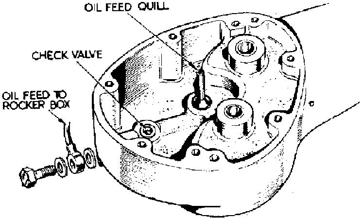
There are more than one type of oil pump worm nut and pump pinions. If at any time hew parts are fitted, check the new ones against the old ones before they are installed. The pump pinions are of the three start type. If the pump is dismantled, on assembly make sure the end plates do not protrude over the pump body; they should be just below the pump body. Check valve. A simple check valve (Fig. 11) is provided to prevent oil seeping into the crankcase when the engine is stationary.
FIG 11 Oil check valve
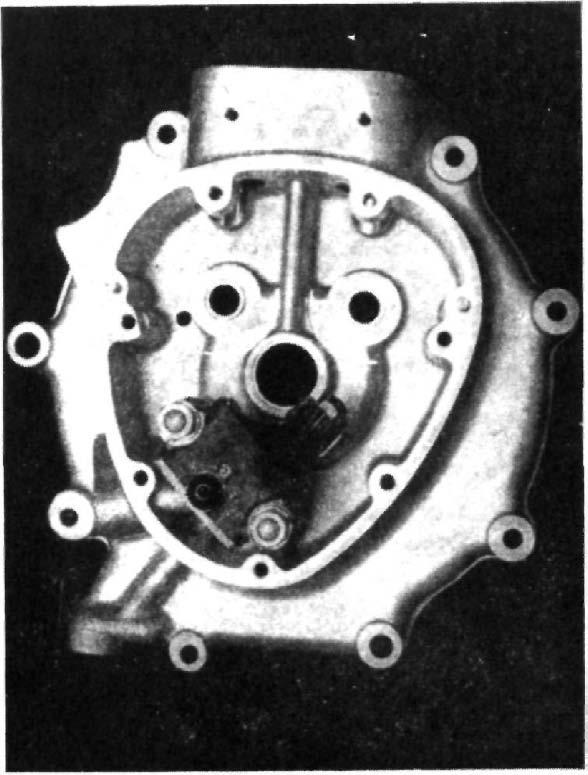
The bearing oil seal. A thin bronze bush is used in the timing side crankcase, this does not constitute a bearing as it is simply an oil seal to stop oil leaking past the roller bearing. 1964 models only. Crankcase bearings. The design of the driving side bearings is unaltered. Details for removal as described for earlier models still apply. A flanged type roller bearing is now used in the timing side of the engine on all single cylinder engines. The bearing sleeve is an interference fit in the crankcase, to take it out the crankcase must be gently heated, then the action of dropping the case on to a flat wood bench will dislodge the sleeve. Separating the crankcase. First take off the oil pump worm drive nut which has a left hand thread. Take off the oil pump, retained by two nuts. Remove the small timing pinion, which now has a parallel bore. With all the bolts passing through the crankcase taken out the case can be parted, the inner member for the roller bearing will remain on its shaft. The flywheels. To take off the, inner member for the roller bearing use two taper steel wedges behind the bearing, once a gap is formed a puller can be used to extract the bearing member from its shaft.
FIG 12 1964 crankcase Tappets and guides. The timing side crankcase tappet guide in situ has two locating diameters ¼" wide at the top and bottom of the guide bousing. The guides are located by a grub screw in register with a vee shaped groove machined circumferentially on the outside diameter of the guide. As the tappet foot is larger than the outside diameter of the guide, the tappet must be taken out from inside the timing chest, after removing the guide. Removing the tappets. With the push rods, timing cover, oil pump, and cam gear removed, take out the grub screws, warm the crankcase, then push the tappet and guide upwards until the guide is clear, then take out the tappet from inside the timing chest. The short interference fit makes it easier to remove the guides.
Fitting tappets and guides. Warm the crankcase, pass the tappet up the guide hole and put on it the tappet guide. Press the guide home until the edge of the large diameter is just flush with the crankcase face, the vee shaped groove should now register with the grub screw hole, fit the screws.
Timing gear. The cam on all single cylinder models for 1964 will not interchange with 1963. Single marking is used on all cams, and for identification each cam wheel is marked with the factory part number. The 500 c.c. scrambler inlet cam is 030124, exhaust 030125. Inlet cam for the 350 c.c. is 030121, the exhaust is 030123. For the 500 c.c. standard engine the inlet cam is 030122, and for the same engine the exhaust is 030123 (same as the 350 c.c). 500 c.c. Scrambler Model. The alternative piston to give a ratio of 12 to 1 is suitable for the new engine, for use with octane 100 fuel. When this piston is. used the ignition timing must be put back to 33° to 34° full advance. For long distance events, the use of a compression plate .050" thick should be used, to maintain engine efficiency. Ignition timing all 1964/65 singles. Maximum advance 350 c.c. 34° (8.9 mm.) 500 c.c. 38° (10.98 mm.) 500 c.c. Scrambler 38° (10.98 mm.) All with the ignition unit fully advanced. ” ” ” ”
On coil ignition models the ignition unit can be advanced by using a tool in the slot provided in the end of the cam. Carburetter settings. 1964/65 350 c.c. models type No. 389/208 Main jet, 260 (with or without air filter) Slide, 3 Pilot jet, 25 Needle jet, .1065 Needle position, central notch 1964/65 500 c.c model Type No. 389/209 Main jet. 290 (with or without air filter) Slide, 3.5 Pilot jet, 25 Needle jet, .106 Needle position, central notch 1964/65 500 c.c. Scrambler Type No. G.P.5 (1 8" choke) Main jet, 310 (with air cleaner 290) Air jet, .125" Slide, 6 Needle, G.P.6, 5th notch.