26 minute read
Gearbox and Clutch


THE GEAR BOX 250 c.c. and 350 c.c. Lightweight Models
It will be seen in Fig. 13 that the gear box internals are situated above the centre line of the gear box shell. It is for this reason that at least three pints of engine oil must be filled and maintained for satisfactory lubrication.
POSSIBLE FAULTS
Top gear disengages. This is most likely to occur on early type gear boxes before 7988 (250 c.c.) and 2300 (350 c.c).
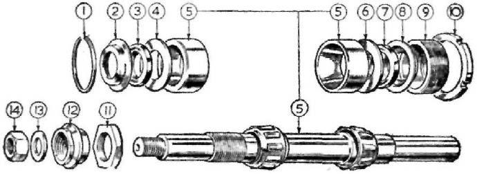
To rectify, discard the sleeve gear 041273 and sliding gear 041276 as shown in Fig. 3. Replace the sleeve gear with modified type 044075, also sliding gear 044076, which use undercut dogs for positive engagement. Should the fault develop on a later type gear box, the plunger 042835 may be damaged on the extreme end, or the spring for plunger 040045 is weak allowing the gear to disengage. Both gears must be changed to convert. Third gear only disengages. The only remedy is to renew the two third gear pinions 041276 and 041277. Usually this is due to bad gear changing and possibly clutch drag. Bottom gear only disengages. This can only be due to end play between the first gear pinion and kickstarter bush. To remedy, use a shim washer .020" thick placed over the layshaft between the pinion and kickstarter bush. Difficulty in selecting the gears. Usually due to a distorted pawl spring 041327 preventing the pawl from rocking. Gear pedal does not centralise. The footchange pedal spring is broken. Replace with improved cross over type 043453. Separate the legs when fitting.
FIG 13 Lightweight gearbox with end cover removed
First gear modification. In gear boxes made before number G8603 (250 c.c. model) and M2701 (350 c.c. model) a plain layshaft first gear 041291 was used. This is superseded by a bushed pinion 044080. The new first gear can be used with the existing second gear pinion. Wear on kickstarter axle bush. Only likely to occur on early models with gear box numbers before G6014. This can happen if the kickstarter return spring 040043 is overwound, which tends to pre-load the kickstarter bush against the first gear pinion. Gear boxes after the above number are fitted with a circlip 042900 encircling the kickstarter axle 042130 with a thrust washer 042901 to prevent pre-loading also wear on the axle bush. The new parts can be fitted to earlier type gear boxes. Oil leaks. Two metal discs or core plugs are used to seal the aperture for the layshaft and quadrant spindle. These discs are a press fit in the gear box shell.
To rectify an oil leak from this part of the. gear box it is necessary to take away the primary drive and rear portion of the front chaincase as described in removing the engine. Take out the gear box internals to drive out the discs and use replacements. Clean all traces of oil from the two apertures, apply jointing compound and tap the new discs into position. Allow plenty of time for the jointing compound to set before refilling gear box with oil. Oil leaks from end covers. Can only be due to a broken or deformed gasket. Stick the gasket with jointing compound to the gear box shell before refitting the cover. Dismantling the gear box. (All nuts are right-hand, except rear chain sprocket nut 041271.) With the gear box in the frame and clutch removed:
Remove exhaust pipe and silencer in one piece.
Remove right side footrest arm.
Remove gear indicator bolt 040137.
Remove gear change pedal, by releasing the pinch bolt.
Remove four screws securing the fairing and take it away. Gear box end cover. Take out the gear box drain plug, catch oil in a suitable receptacle.
Remove ratchet nut 041340 and ratchet 041283.
Remove six screws securing end cover, take off cover then remove ratchet and nut. The ratchet cannot be removed without taking off the cover. See Fig. 3. Gear box inner cover. Remove clutch inner cable from lever.
Remove, by unscrewing clutch body lock ring 041280, use a soft drift and hammer.
Remove clutch operating body 042141 (watch for a" ball inside).
Remove mainshaft nut 041265.
Remove ratchet nut 041340 and washer.
The cover can now be removed exposing internals, Removing gear box internals. Remove footchange quadrant 041334 with spindle assembled.
Remove, by unscrewing selector fork shaft 041345 (use a spanner on the two flats).
Remove gear cluster with mainshaft, layshaft and two striker forks.
The plunger 042835 together with its spring 040045 will remain in the gear box shell. Removing sleeve gear and sprocket. Remove the rear chain. The sleeve gear sprocket nut 041271 has a left-hand thread. As the sprocket on the sleeve gear is subject to reversal by accelerating and decelerating the sprocket nut must be positively tight. In consequence the sprocket 041269 must be firmly held during the process of unscrewing, or tightening the nut. A chain bar is easy to fabricate. Use a short length of ½" x .305" chain attached to a bar of suitable length, which is the best medium of holding the sprocket.
Turn back or flatten the tab washer between the nut and sprocket. Use a well fitting ring spanner 1½" across the fiats to release the nut. Removing the sleeve gear. With the sprocket removed, press or gently tap the gear into the gear box shell. Removing sleeve gear bearing. Prise out the oil seal, note the way it is fitted. Use a suitable drift to drive out the roller bearing. The distance piece 041391 will remain in gear box shell.
Remove bearings from gear box shell. Push out the two metal caps 041394/5 then drift out the layshaft bush 041289 and bush for footchange spindle 041307.
It is most unlikely that the spindle bush will be affected by wear. NOTE—The roller bearings for the sleeve gear are self-aligning and can be waggled about when unsupported by the mainshafts. This can give an erroneous impression that the bearing is badly worn. Removing bearing from inner cover. Support firmly the cover and press out the bush 041299. The kickstarter axle bush 041298 goes into a blind hole. Screw a coarse thread tap into the bush, and pull out the bush.
There is a peg to locate the clutch body 042141, watch this, when using a drift to extract the ball bearing 012545 for the mainshaft.
Two oilite bushes 042145 are used for footchange spindle. Carefully note their location before driving out. An “O” ring 040006 is used between the outer bush and the cover, which should be discarded before fitting new hushes. Removing sleeve gear bushes. Support the gear in a vice (note the location of the two bushes), then drift out. Refitting the bearings. The oilite bushes in the outer cover are made to size and do not require reaming.
Ream the layshaft bush in gear box .6260" to .6255". Refitting sleeve gear bushes. These two bushes are thin and somewhat brittle. Oil the outside diameter of each bush, insert them squarely in the gear and gently press into position.
Ream both bushes .689" to .688" in. situ. Refitting the sleeve gear sprocket. The flat side of the sprocket should face outwards (away from the gear box) see instructions on removing sprocket nut. Refitting The oil seal. The metal backing faces outwards. Gently and squarely tap the oil seal into position. Assembling the gear box internals. The assembly sequence of the various
pinions is clearly illustrated. Ensure the plunger and springs are in position in the gear box shell.
For clarity, assemble in the following order: (1) Fit footchange spindle and quadrant. (2) Take up the main shaft fit first, second and third gear, enter shaft through sleeve gear. (3) Fit mainshaft selector fork and locate it in quadrant. (4) Take up layshaft fit second and third gear, enter shaft in bush. (5) Fit layshaft selector fork and locate. (6) Pass selector fork shaft through both selectors and screw home. (7) Fit low gear pinion. Precautions during assembly of gear box. (1) Make sure the selector forks 041341/3 are correctly indexed. (2) If the end cover does not go back properly, do not use force, take off the cover and find out what is wrong. (3) Make sure all gaskets are undamaged, stick them on to the gear box and covers some time before they are refitted. (4) Make sure the small peg inside the ball race housing has not fallen out. This locates the clutch operating body, (5) Insert the pin 042143 for clutch body from the top end. If this pin is a loose fit, give the top end a few light blows with a hammer to deform it and make it fit tight. (6) Put a little clean oil on all moving parts. DO NOT OMIT TO FILL THREE PINTS (1.8 LITRES) OF SAE 50 OIL. The kickstarter axle. Should it be necessary to dismantle the kickstarter, take off the gear box end cover as described elsewhere. The ratchet pinion 041300 is in tension by the ratchet spring 041358. To relieve this tension temporarily, fit the kickstarter crank, and depress it which will release the pinion and enable it to be taken away.
Remove the circlip encircling the shaft, should one be fitted, prise out the end of the return spring 040045, the shaft can now be extracted. CSR Models. The gear box for the CSR model is identical to the standard machines, with the exception of the clutch, which is the same as used on the 350 lightweight. See technical data for gear ratios.
CLUTCH—LIGHTWEIGHT
To dismantle the clutch, remove outer portion of front chain case (see ENGINE SERVICE).
Remove the three clutch spring adjusters, take out the springs and cups.
Take out the clutch plates, noting the order in which they are removed.
Remove the clutch body from the mainshaft. Use a box spanner F" across the flats. Engage top gear, use the tool to stop the clutch from rotating whilst the nut is unscrewed as shown in Fig. 8. Alternatively press hard on the rear brake lever to hold the clutch stationary.
Usually the clutch will came off the shaft splines without the use of an extractor tool.
Friction material is bonded to the plate. When new the segments protrude 3 / 64 ".
Check the steel plates. If they are not flat, the clutch will slip. Put all
the steel plates together, hold them up to the light when it will be seen if one or more of the plates are buckled. Later type plates are "dimpled" to prevent buckling,
Check the free length of the clutch springs which should be 1¾" overall length. Assembling the clutch. The sequence of assembly is in the following order: 250 c.c. model. (1) Thick steel back plate chamfer inwards. (2) Plain steel plate. (3) Friction plate (double sided). (4) Plain steel plate. (5) Friction plate (double sided). (6) Plain steel plate. (7) Friction plate (single sided). 250 c.c. Scrambler. (1) Thick back plate. (2) Plain steel plate. (3) Friction plate (double sided). (4) Plain steel plate. (5) Friction plate (double sided). (6) Plain steel plate. (7) Friction plate (double sided). (8) Plain steel plate. (9) Friction plate (single sided). 350 c.c. model. (1) Thick back plate (recess for back plate inwards). (2) Friction plate (double sided). (3) Plain steel plate. (4) Friction plate (double sided). (5) Plain steel plate, (6) Friction plate (double sided). (7) Plain steel plate. (8) Friction plate (double sided). (9) Plain steel plate. Dismantling the clutch shock absorber. With the clutch removed, take out the three countersunk screws, prise out the cover plate 043187.
Use an old gear box mainshaft held in a vice and put the clutch body on the shaft. Use the tool shown in Fig. 14 then compress the large rubbers, by leverage, use a pointed spoke to pick out the thin rubbers. The thick ones will come out without difficulty.
Use the same method if the gear box is still in the frame, with top gear engaged and pressure on the brake pedal. Very firmly tighten the plate screws and centre pop between the screw head and the plate. Assembling the clutch. After replacing the rubbers, make sure that the three screws are well tightened, then centre pop the screws for security as these screws are prone to come loose. The clutch bearing. The bearing race plate is shown in Fig. 3 part No. 043196. After removing the clutch, take out the three stud nuts 040356,
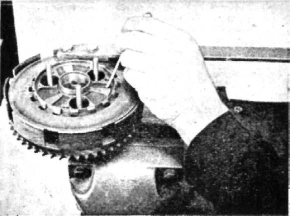
FIG 14 Removing clutch shock absorber rubbers
then the plate 043195, to expose the rollers and cage. Note the closed end of the roller face faces the plate 043195. To remove clutch cable. Remove oil filler cap from kickstarter case cover.
Screw right home the clutch cable adjuster, as far as it will go.
Disengage the cable from the operating lever inside the cover. The cable, after removal from the handlebar lever, can be pulled through the clips fixing it to the frame. Clutch spring adjustment. Should clutch slip develop, first make sure the operating mechanism is in correct adjustment (see clutch adjustment). The correct position for the clutch spring adjuster nuts is—the spring stud should just protrude through the recess in the adjuster nut. Clutch adjustment. Attention to the clutch is usually confined to adjustment of the operating mechanism. To avoid clutch slip or drag, it is essential to have x" free movement between the clutch outer casing and the clutch cable adjuster. Without such movement the operating mechanism will be pre-loaded causing wear on the operating parts, also clutch slip. Conversely, excessive movement in the clutch cable will prevent separation of the friction plates and cause the clutch to drag, thus making the gear selection difficult.
As the clutch inserts tend to settle down, this has the effect of lengthening the clutch push rod, as the width of the friction inserts are slightly reduced. To deal with clutch drag, or clutch slip, first unscrew the clutch cable adjuster lock nut which is located at the handlebar end, run down the adjuster as far as it will go. Remove the clutch inspection cap, unscrew one or two turns the adjuster lock nut 040376, shown in Fig. 3.
With a screwdriver, screw in the adjuster until contact with the push
rod can be felt, unscrew the adjuster exactly half a turn and retighten the lock nut, taking care the adjuster does not move. Complete the adjustment by unscrewing the clutch cable adjuster until there is x" movement between the outer casing and the adjuster, tighten the lock nut. Replace the inspection cap.
Clutch slip should be dealt with promptly otherwise the friction plates will be damaged and the clutch springs affected by heat. The normal free length of the clutch springs is 1¾", the clutch push rod length is 10". LIGHTWEIGHT GEARBOX MAINSHAFTS 350 c.c. Lightweight. Mainshaft 041701 was fitted to gear boxes with numbers from zero to 3757.
An improved type mainshaft 041703 was first used in gear boxes 3758 and onwards. 250 c.c. Lightweight. Mainshaft 041263 is used on gear boxes from zero to 9974, also to gear boxes between numbers 10064 to 10128 as a temporary measure.
A modified shaft type 043058 is used in gear boxes with numbers 9975 to 10063 inclusive, which is now the current type.
The dimensions affecting the various mainshafts are given in Figs. 15 and 16, the drawings are to scale. NOTE—The shaft dimensions affect the vaned shock absorber centre. For mainshafts 041263/041701 use shock absorber centre 043186. For mainshafts 043058/041703 use shock absorber centre 013509.
THE GEAR BOX Heavyweight Models
Gear box faults. If difficulty in changing gear from top to third and where it has been ascertained that the clutch is not dragging, the fault can be rectified by attention to the gear change stop plate (55). Take out the plate bolts (73), disconnect the pawl spring. Draw out the two plate holes by elongation to the extent of Q" to enable the plate to go upwards towards the top of the case. The plate must be retained in this position whilst retightening the two bolts. Should the fault occur when changing into a higher gear, elongate the holes in the opposite direction to the same amount, so that the plate can be moved downwards.
To summarise, if the fault is in changing down move the plate upwards, conversely if the fault is when changing up, move the plate down.
If gear selection is generally uncertain, first verify the location of the pawl spring (88). If this spring is distorted or fitted upside down, gear selection will be uncertain. The correct position is with the straight leg of the spring uppermost. Oil teaks from kickstarter axle. Check oil content by removing level plug (87), normal content one pint, or 20 fluid ozs., if normal. Renew the 'O' ring (69) see details 'removing bushes', Wear on kickstarter pawl (41). Usually due to a weak kickstarter return spring, causing the crank to depress by inertia over bumpy road surfaces. If the crank is too far away from the vertical position the inertia will increase.
Position the crank approximately 20° left of the vertical position.
MAINSHAFT 041701
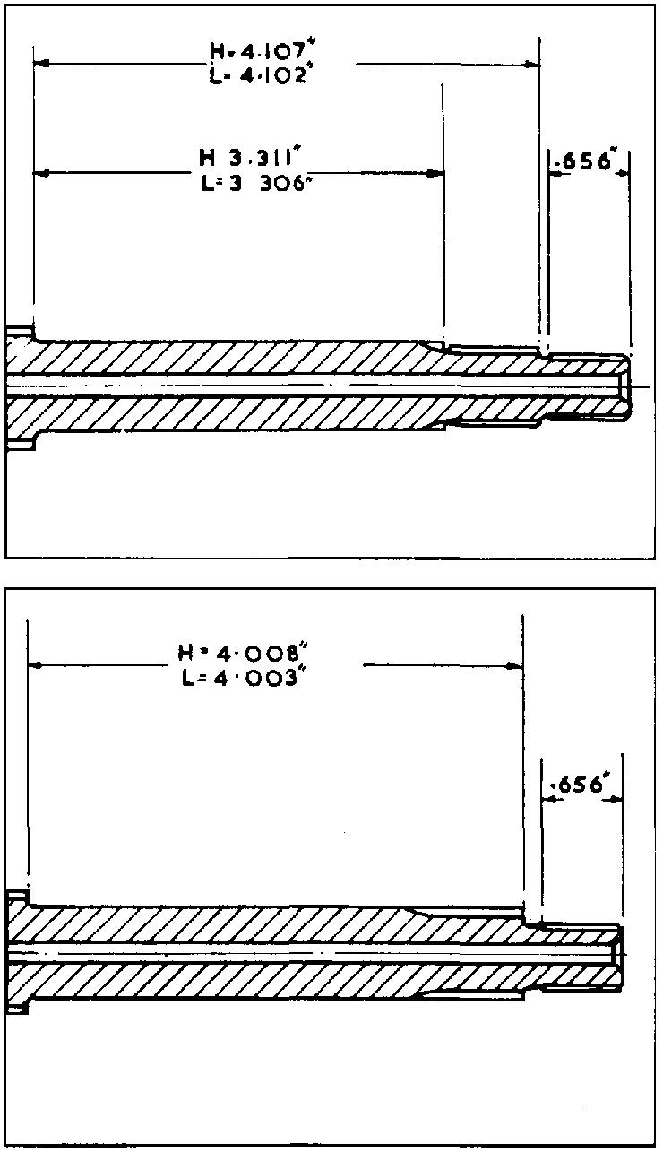
MAINSHAFT 041703
FIG 15
MAINSHAFT 041263
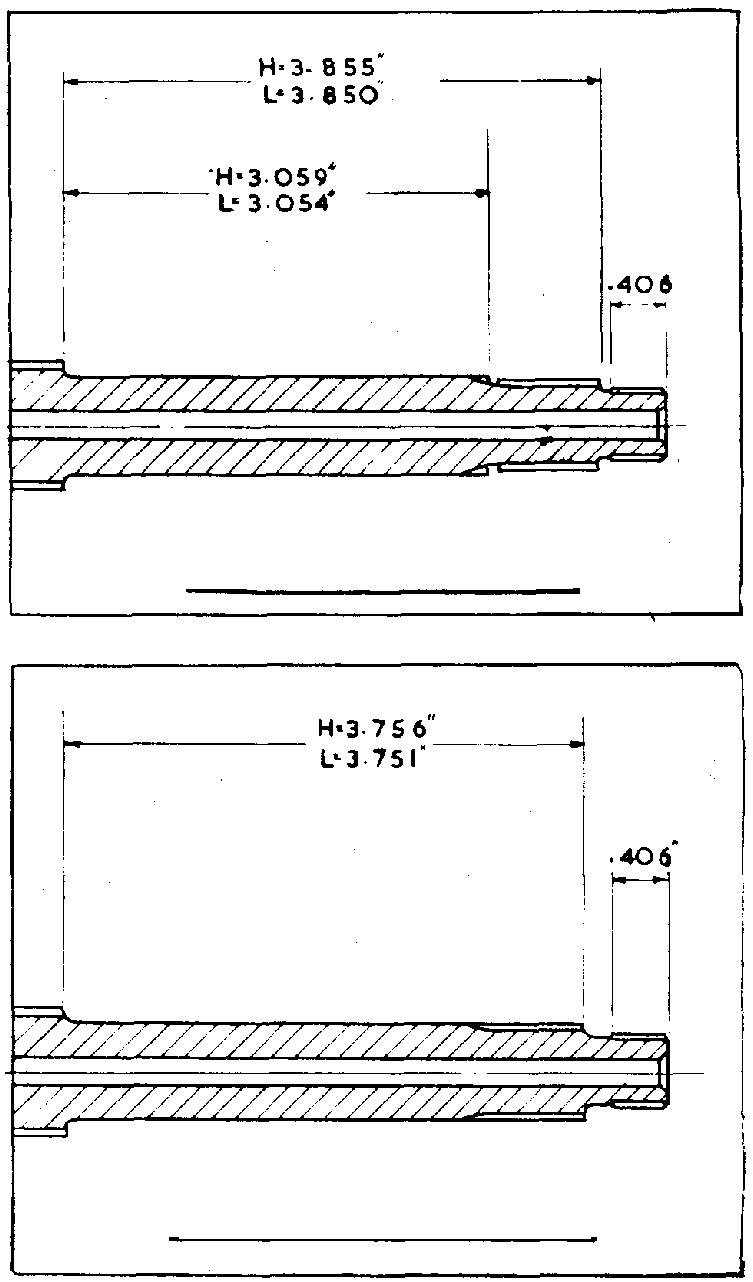
MAINSHAFT 043058
FIG 16
Damaged kickstarter stop plate (94). Can only be due to violent backfire causing excessive ignition advance, or too much throttle when starting. Drill the rivet head to remove swaging and push out the pin. Kickstarter spring disengages. This is due to the end of the spring taking 'a set' where is is located in the cover. Usually it is preferable to fit a new spring. Gear box noises. First check oil content. After considerable mileage check layshaft bearing for wear, also layshaft fixed gear pinion (36). Removing the kickstarter axle (45). Lever out the kickstarter return spring from its anchorage in the cover, the opposite end of the spring will come out easily, then pull out the axle. To replace kickstarter assembly. Fit kickstarter axle, with pawl assembled in cover, turn the axle so that the hole in it for the return spring is at 12 o'clock.
Fit return spring on the axle, insert the end of the spring, which is turned down vertically into the hole drilled in axle. Using tool recommended for spring removal, hooked in opposite end of spring, pull the spring sufficiently to enable the turned in end to enter hole drilled in the cover.
Replace inner and outer cover as detailed previously. Dismantling the gear box. (Figures in parenthesis apply to Fig. 17.) If the gear box is to be completely dismantled, first remove the clutch as detailed for 'removing engine from frame', including the rear portion of the front chain case. Have available a new set of gaskets. Removing the outer cover (56). Remove drain plug (15), catch oil as it drains.
Remove inspection cap (66) and disconnect clutch cable inner wire,
Remove bolt for indicator (62) leave pedal in position.
Remove kickstarter crank bolt (90) and take off the crank.
Remove five cheese-headed screws securing cover (68).
Remove cover by pulling on the gear change pedal. Removing the inner cover (47). Remove ratchet plate and spindle (5).
Remove clutch operating arm and roller (82).
Remove lock ring (80), take away the body and ball.
Remove mainshaft nut (74).
Remove seven nuts (89) securing the cover.
Remove cover by tapping the rear portion until it is clear of the dowels. Removing gear box internals. Remove low gear on mainshaft (39).
Remove striker fork (25) by unscrewing.
Remove striker forks (33 and 34).
Remove clutch push rod.
Remove mainshaft (11) with the gears on it.
Remove layshaft and gears; it may be necessary to rock the shaft sideways to extract from bearing. Removing the cam plate (26). Remove the dome nut (20) and take out the spring and plunger.
Remove two bolts (28 and 29) over the plunger housing.
Remove the cam plate and quadrant. Removing the sleeve gear (23). Remove screw fixing lock plate (4).
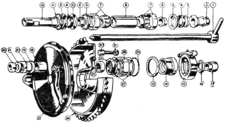
FIG 17 Heavyweight gearbox
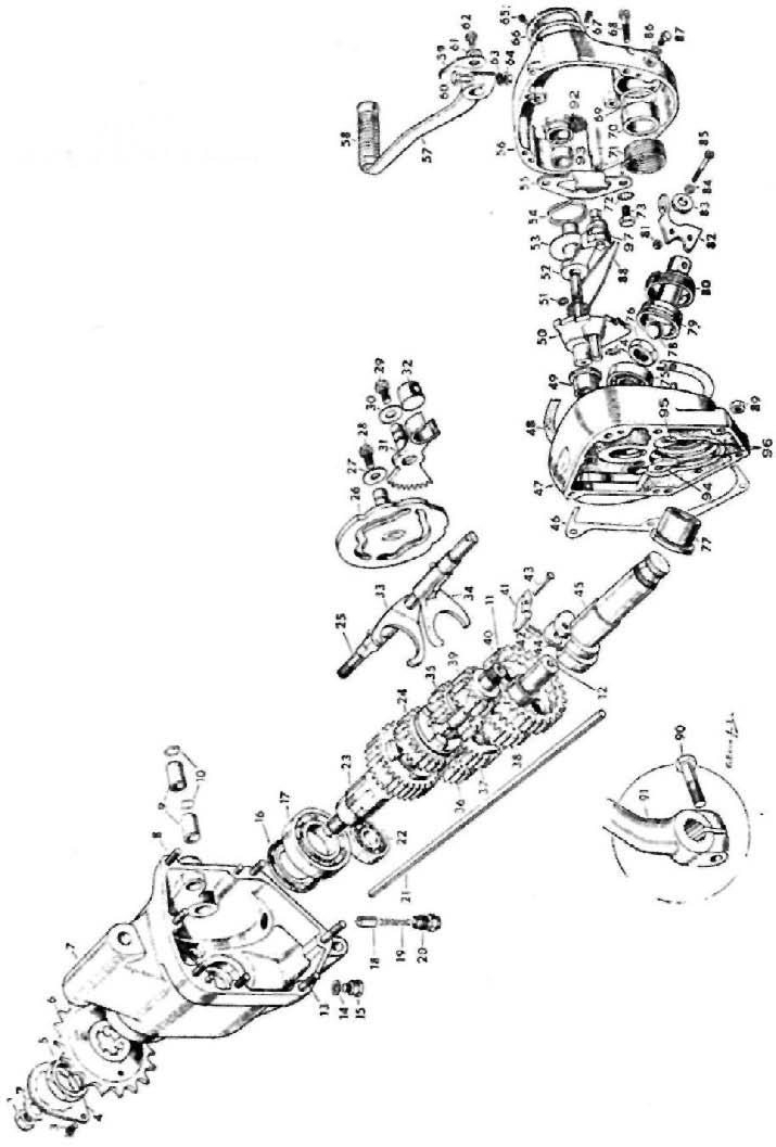
1 Clutch retaining nut 2 Washer 3 Locking screw 4 Locking plate 5 Locking nut 6 Drive sprocket 7 Gearbox shell 8 Stud (short) 9 Bush 10 'O' ring 11 Mainshaft 12 Layshaft 13 Stud (long) 14 Washer 15 Drain plug 16 Sleeve-gear oil seal 17 Main gear ball race 18 Index plunger 19 Spring 20 Domed nut 21 Clutch push rod 22 Layshaft ball race 23 Main gear 24 Mainshaft third gear 25 Selector-fork shaft 26 Cam plate 27 Washer 28 Bolt 29 Bolt 30 Washer 31 Quadrant 32 Roller 33 Selector fork 34 Selector fork 35 Mainshaft second gear 36 Layshaft small pinion 37
38
39
40
41 42 43 44 45 46 47 48 49
50
51 52 53 54 55 56 57 58 59 60
61 62
63
64 65
66 67 68 Key to FIG 17
Layshaft third gear pinion Layshaft secondgear pinion Mainshaft firstgear pinion Layshaft firstgear pinion Kickstarter pawl Plunger Pin Spring Axle Gasket Inner cover Gasket Gear-change spindle bush Ratchet plate and spindle 'O' ring Pawl carrier Washer Return spring Stop plate Outed cover Foot-change lever Rubber Indicator Foot-change lever bolt Indicator washer Indicator fixing bolt Foot-change lever washer Nut Inspection-cover screw Inspection cover Gasket Outer-cover screw 69 70 71 72 73 74 75
76 77
78
79
80 81 82 83 84 85 86
87 88
89 90 91 92
93 94
95
96
97 Kickstart 'O' ring Bush Return spring Stop-plate washer Stop-plate screw Circlip Mainshaft ball race Mainshaft nut Kickstart-axle bush Clutch operating ball Clutch operating body Lockring Clutch-roller nut Operating lever Roller Sleeve 2B.A. screw Oil level-plug washer Oil-level plug Foot-change-pawl spring Nut Kickstart bolt Kickstart crank Pawl carrier 'O' ring Pawl carrier bush Kickstart axle stop Kickstart axle cam Kickstart axle cam rivet Footchange pawl
Remove sleeve gear sprocket nut (5), which has a left-hand thread.
Use a good fitting ring spanner across the flats and refer to method of removing this type of sprocket nut described for Lightweight gear box.
Remove sleeve gear Sprocket which is splined; also distance piece.
Remove sleeve gear by tapping it through the bearing (17). Removing sleeve gear bushes. Two thin bushes of the Oilite type are used as a bearing for the mainshaft.
Note the location of these bushes in situ, before they are pressed out. As the material is somewhat brittle, exercise extreme care in pressing in the new bushes.
The internal diameter of both bushes in situ is .81325" to .81200". Removing sleeve gear bearing (17). Remove by prising out the oil seal (16) and sleeve for seal.
Remove bearing after first heating shell and drift out.
Alternatively drop the shell face downwards on a clean bench, when this bearing, also the layshaft bearing (22), will drop out. Removing the hearings. Pre-heat the inner cover and press out from inside the case the mainshaft bearing (77).
If desired the kickstarter axle bush can be extracted at the same time. To do this, firmly support the inside face of the cover and press out the bush from outside the cover. Removing the footchange spindle bush (99). This is fitted into a blind aperture. Pre-heat the case and screw in a coarse threaded tap to extract. Use the same method to remove the bush in the kickstarter axle. NOTE—The footchange bush does not require reaming when renewed. If the kickstarter axle bush 040146 is renewed, ream to .6875" to .6865"' in situ.
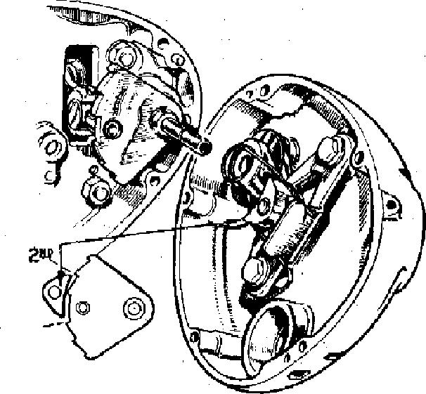
FIG 18
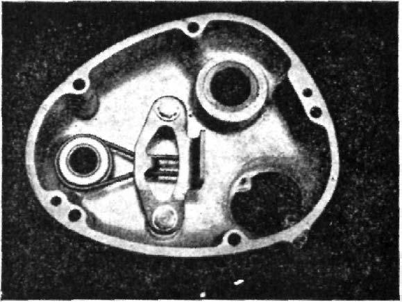
FIG 19 Re-assembling the gear box. NOTE— Apply some clean oil to all moving parts before fitting.
Fit the sleeve gear ball race (17) and layshaft bearing (22), pre-heat the shell and ensure bearings are entered squarely; apply a little clean oil.
Fit sleeve gear through bearing, and oil the sleeve or distance piece for oil seal.
Fit sleeve gear sprocket and firmly tighten left-hand sprocket nut.
Fit lock plate and screw. Refitting the cam plate (26). The cam plate must be correctly positioned on assembly, otherwise the four gears will not be indexed properly. (1) Fit the quadrant (31) also its bolt and washer. (2) Raise the lever portion of the quadrant, with the radius of the lever in line with the top right hand cover stud (top gear). (3) Insert the cam plate so that the first two teeth of the quadrant can be seen through the slot in the cam plate, then fit the bolt and washer (27). Fitting the internals: (1) Insert the mainshaft and fit to it the third gear (24). (2) Fit the second gear (35) with the striker fork (33) in the pinion groove, then insert the projection of the striker into the groove in the cam plate. (3) Fit the first gear (39).
Assemble the layshaft by: (4) Fitting the fixed gear (36), third gear (37) and second gear (38) with the striker fork (34) in the slot for second gear. (5) Insert the projection of striker fork into cam plate slot, with layshaft in the bush. (6) Line up the two holes in the striker forks and pass through the
spindle (25) and firmly tighten. (7) Fit the first gear (40). To complete the assembly. Insert the roller (32) into the quadrant in position to receive the spindle for the footchange. Examine the gasket (46) for blemish, locate it and refit the inner cover. Before finally tightening the clutch body lock ring (80) verify the operating lever (82) is in line with the clutch cable entry, to ensure a straight pull on the inner wire. Do not use force, if the cover does not go home easily, take it off and find out why. Check the position of the pawl spring (88) and refit the outer cover. Refill one pint of SAE 50 oil. Replacing the footchange pedal spring. With the outer cover removed, take out the quadrant (50) and the pawl spring behind it. Tap out the footchange sleeve (52) and its washer (53), Remove two bolts (73) and lift away the plate,
The position of the pedal spring assembled is shown in fig. 19.
CLUTCH—HEAVYWEIGHT
Three types of clutches have been used since 1957. The original design had loose friction inserts in the clutch sprocket, also in the friction plates. This type of clutch was used on all Heavyweight Models up to 1959, with the exception of the CSR Models, which were equipped with the bonded type clutch.
All 1960-61 Models, use bonded type clutches.
For the 1962 season a heavy duty five-plate type clutch was introduced for 650 c.c. CSR Models, which can be used on any earlier model.
The early type clutch can be converted by using the following components: 1 Back plate 040584. 1 Clutch sprocket 040359. 4 Steel plates, plain 043191. 4 Friction plates 043192. 1 Friction plate 043193. Clutch slip. To enable the clutch to function satisfactorily it is essential to have clearance between the clutch push rod and the thrust stud. The fact that there is play, or lost motion, at the handlebar lever end does not guarantee there is clearance between the push rod and thrust stud.
To obtain the correct adjustment run down, as far as possible, the clutch cable adjuster. Remove the chain case cap for the clutch. Release the nut using a screwdriver, screw in the thrust stud until it just touches the clutch push rod.
Unscrew the thrust stud half a turn then retighten the lock nut with care to avoid the stud moving during this process. Now reset the cable adjustment by unscrewing the adjuster, leaving 8" to x" free movement between the outer cable and the adjuster.
If the fault prevails, take down the clutch and check the steel plates for buckle. Put all these plates together and hold up to the light, which will indicate if one or more of the plates are buckled, which reduces the friction area.
1 Back plate (bonded) 2 Roller cage 3 Rollers (15) 4 Race plate 5 Spring studs 6 Spring-stud nuts 7 Centre hub 8 Shock rubbers (large) 9 Shock rubbers (small) 10 Shock plate 11 Shock-plate screws 12 Shock centre 13 Sprocket 14 Friction plates (double) 15 Steel plates 16 Friction plate (single) 17 Pressure plate 18 Pressure-plate adjuster 19 Pressure-plate-adjuster nut 20 Spring cups 21 Springs 22 Spring adjusting nuts
FIG 20 Clutch components
Replace buckled plates with the new type.
An excess of oil in the front chaincase will adversely affect the dutch. Friction plates so affected should be de-greased as they are usually serviceable. Avoid the use of petrol or paraffin and use trichloroephylene. Alternatively, copiouslv dust the inserts with Fullers Earth to absorb the oil.
Check also the clutch spring cups, which may be fouling the holes in the alloy pressure plate, preventing the spring from exerting maximum pressure. Apply a little grease to the cups before refitting. Clutch springs. If the clutch has been slipping for any length of time, the heat generated is calculated to weaken the springs, which should be renewed. The correct free length is 1G". The five plate clutch spring free length is 1 n". Discard springs which have collapsed to the extent of x". Clutch spring adjusting screws. If there is a tendency for the springs adjusting screws to become unscrewed, take out the spring, lift up the end of the spring with a pen-knife and file the end of the spring to give a square abutment of 8" or get rid of the feathered end. The abutment will then come up against the indentation at the back of the adjuster and prevent it unscrewing. The correct location of the adjusting screws is with the head of the spring stud just flush with the face of the adjusting screw.
If the machine is a combination and heavy loads are carried, and the early type clutch is used, convert the clutch to the bonded type as already described. Clutch drag. This is due to torque on the gear box mainshaft and creates noisy gear engagement. The cause is due to the clutch plates not separating when the clutch is operated. The fault may be due to: (1) Excessive play in the operating mechanism (see clutch slip). (2) Uneven adjustment of the clutch springs. (3) The steel plates are buckled. (4) The clutch plates are gummy.
In the case of (2), take off the outer portion of chaincase, operate the clutch lever and note if the outside plate is withdrawn parallel with the plate behind it. If the gap between the two plates is uneven, manipulate the spring adjuster until the gap is equal and evenly between the two plates, with a preference, for screwing in the adjuster to balance.
In the event of (4), treat the clutch plates as recommended for clutch slip to get rid of the gumminess.
Needless to say, continual use with clutch drag can cause damage to gear box pinions. Clutch nut works loose. If the mainshaft nut securing the clutch to the mainshaft works loose, this is due to damage to the splines in clutch centre for the shock absorber 040354. To remedy, replace the centre and avoid over-tightening the mainshaft nut. To remove a clutch control cable. Remove the oil filler cap from the kickstarter case cover.
Screw right home the clutch cable adjuster that is located in the top of the kickstarter case cover.
Disengage, from the operating lever, the clutch cable inner wire by