22 minute read
Engine servicing


Oil tank Tyres Oil tank/Reservoir
Ignition Gear box Chaincase
Battery
Oil tank/Reservoir Rear chain Gear box Hubs Expanders Steering head Small parts
Chaincase
Air filter
Oil Reservoir
Filter Rear chain Brake pedal Speedometer
Ignition Plug Steering head
Bolts and nuts
Rockers
Oil tank WEEKLY Check level and top-up if necessary. Check pressures and inflate if necessary. EVERY 500 MILES Drain at first 500 miles, re-fill with new oil and clean filter. Check contact breaker points. Drain at first 500 miles and re-fill. Check level of oil when machine is standing vertically on level ground. Fill up if level is low. (See chain lubrication.) Inspect each cell for level of electrolyte and top up with distilled water if necessary. Level of electrolyte should be just over top of plates. Beware of overfilling. EVERY 1,000 MILES Drain at first 1,000 miles and re-fill with new oil. In wet weather remove and soak in molten grease, Check oil level. Inject small amount of grease Inject small amount of grease Inject small amount of grease } where provision is made Smear all moving parts with engine oil and wipe off surplus, Drain, and re-fill, or monthly. EVERY 2,000 to 5,000 MILES (according to road conditions) (If fitted) clean and re-oil filter element. EVERY 3,000 MILES (Lightweight models) drain and re-fill with new oil. If machine is used for short journeys, renew oil every 3 months. (Lightweight models) clean filter in crankcase. In dry weather remove and soak in molten grease. Inject small amount of grease. Inject small amount of grease into speedometer gear box, if fitted with grease nipple. Clean contact breaker points and re-set if necessary. Clean sparking plug and re-set points as necessary. Test steering head for up and down movement and adjust if necessary. Check all nuts and bolts for tightness and tighten if necessary but beware of over-tightening. Check OHV rocker adjustment and correct if necessary. EVERY 5,000 MILES (Heavyweight models) drain and re-fill with new oil. If machine is only used for short runs renew oil every three months instead of mileage interval.
Ignition Dynamo Front fork
Carburetter
Magneto & Dynamo
Air filter (Heavyweight models) clean metal mesh filter in oil tank, Clean and adjust as detailed in Electrical section. Clean as detailed in Electrical section. Check each side of front fork for hydraulic fluid content and, if necessary, top up. Insufficient oil content is indicated by abnormally lively action, Remove carburetter float chamber side cover and clean interior. Also detach petrol pipe banjo and clean gauze strainer, EVERY 10,000 MILES Get a Lucas Service Station to dismantle, clean, lubricate and generally service. (If fitted) renew filter element,
ENGINE SERVICING—ALL MODELS
Tappet adjustment. The top ends of the two long push rods have screwed extensions. These are locked in position by nuts, thereby providing tappet adjustment. The correct tappet clearances, with valves closed and engine warm (not hot) is nil. This means the push rods should be free enough to revolve and, at the same time, there should be no appreciable up and down play. See fig, 3a on p. 25. Prepare to adjust tappets by:
Set piston to T.D.C. (both valves closed).
Remove the three nuts, and fibre washers under them, retaining tappet cover to rocker box.
Take away cover. Adjust tappets by:
With spanners, hold the sleeve, either valve and slacken lock nut. Then screw, in or out, the head until the clearance is nil. Tighten lock nut and re-check the clearance. Finally
Check adjustment so that, with no up and down movement, the long push rods are free to revolve when the valves are closed. Complete adjustment by:
Replace rocker tappet cover taking care to replace fibre washer that is under each retaining nut,
As mentioned elsewhere do not over-tighten the nuts because the joint is made with a rubber fillet and undue pressure is not necessary. NOTE—In normal conditions tappet adjustment should not be necessary more frequently than about every five thousand miles or after decarbonising and grinding valves. If adjustment is found necessary more frequently the cause should be investigated at once.
For service work on the upper part of the engine, with the exception of tappet adjustment, the twin seat and petrol tank should be removed for accessibility. To remove the rocker box. Remove the three nuts and fibre washers securing the rocker box cover, also the sparking plug. 23
Turn the engine until both valves are closed, i.e. after the inlet valve has opened and just closed.
Remove two nuts and the bolt securing the engine steady bracket to the rocker box and frame. Disconnect valve lifter cable.
Take out the nine bolts securing the rocker box to the cylinder head (one of these bolts is inside the rocker box). The location of these bolts roust be noted as they are dissimilar,
Tilt upwards the right side of the rocker box, extract both push rods and identify their location for replacement in their original positions, remove the rocker box from the cylinder head. To remove the cylinder head. Remove the exhaust pipe and silencer as one unit, then the accessory compartment cover and air niter tube if fitted. Do not rock the exhaust pipe sideways unduly to extract it from the exhaust port which can cause the end of the pipe to close in and result in gas leakage, with movement between the pipe and the port when the engine is hot. Instead squirt a little paraffin or petrol into the port and try again.
Unscrew the cap on the carburetter mixing chamber, take out both slides, wrap them in a piece of rag and attach it to the frame, out of harm's way. Unscrew the petrol pipe union and take away the petrol pipe. Four sleeve nuts and one bolt retain the cylinder head to the barrel, with these removed, the cylinder head with carburetter attached to it can be separated from the cylinder.
NOTE —Four nuts only are used on heavyweight engines.
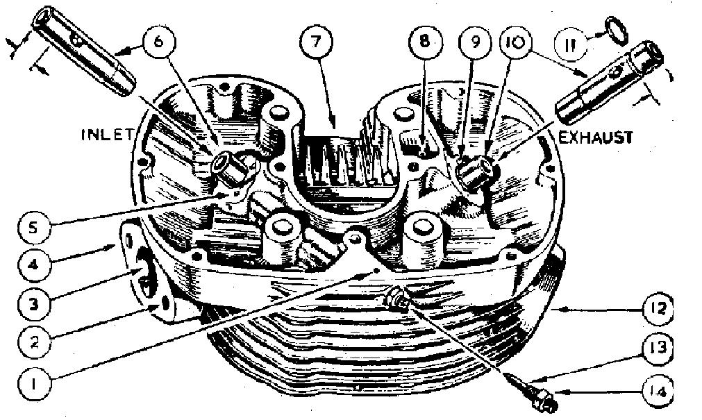
FIG 4 Cylinder head
Decarbonisation. Instead of the usual stipulated mileage interval between periods of decarbonisation, it is recommended that this is undertaken only when the need becomes apparent because of loss in power, heavy petrol consumption or generally reduced performance.
When undertaken, unless it is thought necessary to inspect the piston and rings, the cylinder barrel is best left undisturbed.
Before starting this work have available a gasket set, and if the machine has covered considerable mileage, a new set of piston rings also.
Carbon formed on the piston crown and in the sphere of the cylinder head, can be scraped off with a cheap steel rule, with the sharp corners removed, or similar tool. Deal with the cylinder head before removing the valves, and do not use emery cloth or other abrasives for this work. To remove and replace the valves and guides. The hair pin valve springs are removed by inserting the index finger through the coil of the spring and pulling upwards sharply.
A light tap on the valve spring collar will expose the valve split collets (which should be put in a place of safety), then take out the valve,
Both valve guides are located by an external circlip. The cylinder head must be gently and uniformly heated before attempting to remove or replace the guides.
With the head pre-heated tap the guide upwards out of the port sufficiently to enable the circlip to be prised out of its groove. Reheat the head and drive out the guides through the cylinder head. When refitting the guides, pre-heat the head and verify that the oil holes are in alignment with holes in the cylinder head. Use a valve spring compressor where coil springs are used. Valve grinding. The grinding is accomplished by smearing a thin layer of fine grinding paste (obtainable ready for use at any garage) on the valve face and then, after inserting the valve in the head, partially revolve, forwards and backwards, while applying light finger pressure to the head, raising the valve off its seat and turning to another position after every few movements. (Never revolve the valve continuously in one direction).
When the abrasive ceases to bite, remove the valve and examine its face. The grinding may be considered to be satisfactorily completed when a continuous matt ring is observed on both valve face and seat.
After grinding, all traces of abrasive must be carefully washed off with petrol and a piece of rag, moistened in petrol, should be pulled through the bore of each valve guide to remove any abrasive that may have entered. A holder for the valve, when grinding id the valve, can be supplied. The part number is 017482. Replacing the valves. A valve spring compressor is required to compress the springs and a special tool which is inexpensive, can be obtained from dealers. Before fitting the valve springs, position correctly the valve spring seat. The raised portion on the underside is located with the depression (5) in cylinder head. (Fig. 4.) The inlet valve is the larger of the two valves and it is vitally important to locate correctly the two split collets into the grooves on each valve stem.
Clean the valve guide bores with a piece of clean rag, apply a little
oil on the valve stems and also inside each guide before assembly. Removing the cylinder and piston. With the cylinder head removed, the barrel can be raised vertically to clear the holding down studs. Before doing so, position the engine with the piston on the top of its stroke, have available a piece of clean rag. Raise the cylinder sufficiently to enable the rag to be put into the throat of the crankcase (under the piston) as a precaution against a broken ring falling into the crankcase. then lift the cylinder clear of the four studs passing through it. Make a mark inside the piston to indicate front.
The gudgeon pin is a sliding tit in both the piston and connecting rod. Use round nose pliers to compress and extract the circlip (it is immaterial which one is removed) then push out the gudgeon pin and lift the piston off the connecting rod.
Do not disturb the piston rings unless absolutely necessary.
If new piston rings are used, they are ready for fitting, as the ring gap is allowed for during manufacture,
The top compression ring is chromium plated and has a slightly tapered extension. When new, the word TOP is etched on the ring face to indicate which way it should be fitted. Fit first the scraper or oil control ring, then the two compression rings, to avoid breakage do not expand these rings unnecessarily. Refitting the piston. Before refitting the piston apply a little oil to the gudgeon pin, also to the bosses for the gudgeon pin in the piston. Place the piston over the connecting rod in the same way as it was removed. or in accordance with the marking made, and then introduce the gudgeon pin through the piston, connecting rod and piston bosses.
It is vitally important to correctly locate the gudgeon pin circlip, and a little extra care and time should be devoted to this most simple and important operation. Use round-nosed pliers to introduce the circlip into its groove, using a rotary motion then verify that the circlip is correctly located. Refitting the cylinder barrel. Fit a new cylinder base gasket, after removing broken pieces of the old one. Use a little jointing compound on the base of the cylinder and stick a new gasket to it, no jointing compound should be on the crankcase face. Set the piston ring gaps at 120°. pass the cylinder over the four long studs and lower it gently at the same time compressing each piston ring in turn with the fingers, until the cylinder has passed the scraper ring when it can be lowered on to the crankcase. NOTE—Some clean rag under the piston to fill the throat of the crankcase will safeguard against a broken piston ring falling into the crankcase. Refitting the cylinder head. The cylinder head gasket also acts as an oil seal for the push rod tunnels, consequently it must be in good order if it is to be used again. To avoid the possibility of subsequent attention a new gasket is desirable.
This gasket is neither symmetrical nor reversible and it must be placed on the cylinder in the correct way,
A study of the cylinder barrel face will show an elongated hole (where the push rods operate).
Just behind is a tapped hole for the cylinder head bolt. (Lightweight engines only.) Close to the cylinder bore and to the right of the cylinder head bolt hole is a smaller hole, which is the oil feed passage from the pump to the rocker gear.
Place the gasket on the cylinder so that the oil feed hole in the cylinder registers with the small hole in the gasket.
Put the cylinder head in position, refit the four cylinder head sleeve nuts and the long cylinder head bolt. Do not omit the five washers. First tighten the four sleeve nuts diagonally not one side at a time—then tighten the long bolt, until all are firmly tightened. If a torque spanner is available it should be set to 35 foot lbs. for the four sleeve nuts only. Refitting the rocker box. Before attempting to refit, make sure the piston is on T.D.C. of the firing stroke, with both cam followers down.
Use a new rocker box gasket for this assembly. In the centre portion of this gasket is a projection with a small hole in it. There is also a similar size hole in the cylinder head which is the oil feed passage from the oil pump through the cylinder to the rocker gear. It will be readily seen that if the rocker box gasket is reversed the oil feed passage will be sealed, therefore ensure that the gasket is properly located before fitting the rocker box. With the rocker box gasket correctly located, take up the rocker box, pass all the holding down bolts through it, put the rocker box into position.
Take up the two engine push rods, tilt the right side of the rocker box upwards, then introduce the push rods through the head and cylinder. The exhaust push rod operates with the cam follower nearest to the contact breaker. (See Fig. 3.)
Locate the rocker arms in the push rod adjusters and first tighten the two central rocker box bolts which have screwed extensions.
Tighten the remainder diagonally including the one inside the rockerbox.
Washers are fitted under the heads of all these bolts.
It should be remembered that a soft gasket is used between the cylinder head and the rocker box, therefore the degree of tightness of these bolts is a matter of good judgment and commonsense.
Re-adjust the tappets as previously described.
IGNITION TIMING Lightweight Models
Before setting or checking the ignition timing, make sure the contact breaker gap at full separation, is .012". (See details on Contact Breaker.)
Reference to Fig. 5 will indicate the principle used. To check the timing. Position the engine as detailed for tappet adjustment. Remove the sparking plug, the cover for the contact breaker and engage top gear. Obtain a short length of stiff wire or wheel spoke about 5" long. Insert the wire through the sparking plug hole, until it touches the piston crown. By slowly moving the rear wheel backwards and forwards the top dead centre of the piston travel can be ascertained. Keep the wire vertical as far as the plug hole will permit—make a mark
on the wire to register with the seating for the sparking plug on the cylinder head. Take out the wire and make a further mark on it ¼" ABOVE the previous mark.
Put the wire through the sparking plug hole, then turn the engine BACKWARDS until the top mark on the wire registers with the seating for the sparking plug, the piston is now ¼" before top dead centre. A s" hole is drilled in the contact breaker base plate to enable a small screwdriver to be inserted, and engaged between the two bob weights for the automatic ignition control. (See Fig. 5.)
Turning the screwdriver clockwise will separate the bob weights So the fully advanced position. If the timing is correct the contact breaker points should be just about to separate.
The exact point of separation can best be found by inserting a piece of cigarette paper between the points, which when pulled lightly will be free when the contact breaker points separate.
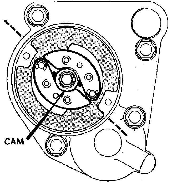
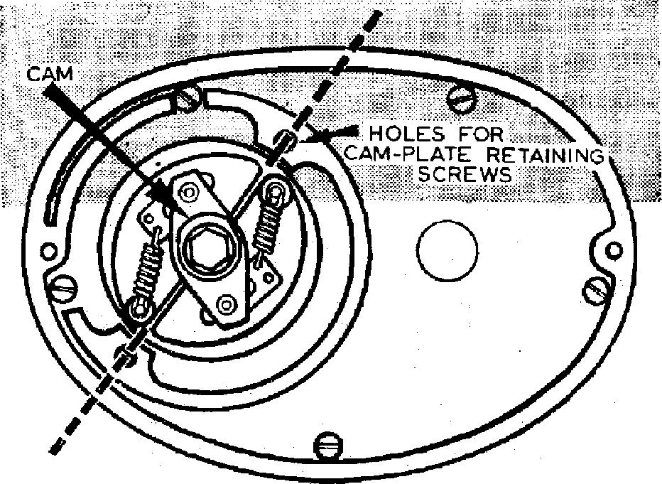
FIG 5 Automatic ignition advance mechanism (approximate ignition setting) To adjust ignition timing. By slackening the two screws in the slotted holes on the contact breaker base plate, the plate can be moved either clockwise or anti-clockwise to adjust the timing as required.
Move the plate clockwise to advance and use the method described for checking to obtain the correct timing.
To reset ignition timing. As the ignition advance is limited to ¼" B.T.D.C, this setting is critical and must be carefully carried out. The automatic ignition control unit is a taper fit on the camshaft, retained by a central bolt. To remove this unit take out the retaining bolt, use in its place a withdrawal bolt, Part No. 042247. Screw home this bolt—do not use undue force—then tap the head of the bolt lightly which will separate the unit from the shaft. NOTE— The contact breaker cam is detachable and if it is inadvertently removed, the timing should be rechecked after refitting the cam, before attempting to start the engine.
The cam wheel, also the small timing pinion which drives it, are both marked to facilitate assembly.
If for any reason, the cam wheel is removed, to re-assemble rotate the engine until the piston is on T.D.C. of the stroke, the mark on the small timing pinion tooth will then be at 11 o'clock. Take up the cam wheel, raise both cam followers, then introduce the cam into the crankcase with the mark on the tooth gap to register with the mark on the small pinion.
These markings have been selected to give the most effective valve timing and best engine performance,
To check the valve timing, as a single piece camshaft is used, it is only necessary to record the inlet valve opening also the exhaust valve closing positions to verify that the valve timing is correct.
The average valve timing, taken with .010" rocker clearance is:— Inlet valve opens 40° B.T.D.C. Exhaust valve closes 40° A.T.D.C.
See TAPPET ADJUSTMENT for running pushrod clearance.
IGNITION TIMING—COIL IGNITION Heavyweight Models
To understand the principle, a study of illustrations should be made. The automatic timing control is a taper fit on the shaft for the inlet cam, retained by a central bolt. The cam separating the' contact breaker points is rotated by two pegs engaged in the plates for the unit springs. As the cam is detachable, the position of the cam should be noted, before it is removed. Before setting the ignition timing it is essential to check the contact breaker gap. Checking contact breaker gap. Remove two screws securing the cover mounted on the timing case, also the cover. Rotate engine to fully separate contact points.
Check gap which should be .014—.016".
To adjust the gap release slightly the two inner screws securing the fixed contact plate and adjust the gap as required by moving the pivot plate in the required direction. Removing the automatic timing control. After taking off the cover:
Remove the two screws passing through the slotted holes in the fixed contact breaker plate and remove the plate.
Remove the bolt securing the automatic timing control to the cam wheel shaft. Fit a 024328 withdrawal bolt in place of the fixing bolt removed which should be lightly tightened. A sharp blow on the end of the withdrawal bolt will dislodge the unit from the shaft.
Do not disturb the contact breaker cam. Setting the ignition timing. Maximum advance 500 c.c. also 350 c.c. with engine number before 41575 is ½" or 39 deg. (12.7 mm). 350 c.c. after 41575. Y" or 34 deg. (8.73 mm). With the A.T.C. retarded use 8" for ½" or x" in place of Y".
To set the timing, have available a stiff wheel spoke or similar object 5½" long.
Remove H.T. cable and sparking plug.
Remove automatic timing control as already described.
Remove the rocker box side cover.
Turn engine so that both valves are closed (inlet valve opens then closes) then engage top gear.
Insert timing rod through sparking plug hole, feel piston by rocking engine forwards or backwards by turning the rear wheel until it can be felt that the piston is at the extreme top of its stroke with both valves closed.
Refer to Fig. 6. and fit automatic advance control, with the gap formed by the two bob weights in line with the two tapped holes, used to secure contact breaker plate. It should be noted that the peak of the cam, or narrowest part, when correctly positioned is approximately at 12 o'clock.
Press the unit firmly on to the shaft that drives it and give the end a sharp tap before re-fitting the fixing bolt. Insert a wood wedge between bob weights to fully separate if fully advanced method is used.
Take up the timing rod, check piston position in case the engine has moved. Hold the timing rod as vertically as possible through the sparking plug hole, verify piston is at the top of the stroke. Make a mark on the timing rod flush with the top face of the sparking plug hole, then withdraw the rod.
If the fully advanced method is used make a further mark on the timing rod exactly ½" ABOVE the previous mark.
With the A.T.C. retarded mate the second mark as shown in the figures given.
Put the timing rod back through the sparking plug hole and by moving the rear wheel turn the engine BACKWARDS until the highest of the two marks on the timing rod is flush with the top face of the sparking plug hole, dependant on the timing method used.
Fit the contact breaker plate with the capacitor at 3 o'clock, lightly tighten the fixing screws. The exact position of contact point separation is best determined by inserting a strip of cigarette paper between the contact points and moving the plate in a clockwise direction until the paper can be pulled away freely.
If a wedge is used to fully advance the unit, scribe a pencil line on the contact breaker plate and a similar Line on the plate housing, both lines in register. Remove the contact breaker plate, take away the wedge and
FIG 6 Setting the ignition timing (Heavyweight) re-fit the plate with the two scribed lines in register, and firmly tighten the fixing screws.
As the ignition timing is important, a re-check should be made, before re-fitting the sparking plug, rocker cover, etc.
MAGNETO IGNITION
To re-time the ignition. The normal advance is 39° (½").
Have available a stout screwdriver, or an old type tyre lever with turned up end, also a small rod or stout wheel spoke 5½" long.
Before setting the ignition firing point it is essential the magneto contact breaker points are correctly adjusted. Therefore always check these first.
Check contact breaker points by:—
Expose contact breaker by removing moulded end cover of magneto (secured by 3 captive screws).
Check setting of contact breaker points and, if necessary, re-set same.
Set ignition firing point by Remove:—
The sparking plug high tension cable from plug.
The sparking plug.
The magneto chain case cover.
The rocker box side cover.
Unscrew, several turns, nut retaining magneto sprocket to camshaft.
(No need to remove nut.)
Lever off sprocket until it is loose on the taper of the shaft. (Use stout screw-driver or old type tyre lever.)
Turn over engine till both valves are closed.
Insert rod through sparking plug hole, feel piston by rocking engine forwards or backwards till it is felt the piston is at the top of its stroke with both valves closed,
Mark rod flush with top face of sparking plug hole. Remove rod and measure ½" above the flush mark and record position on rod
Turn the front plate of the automatic unit with the fingers and thumb to its limit of movement and insert a wood wedge to hold the control in the fully advanced position.
Replace rod in sparking plug hole.
Slightly rotate engine BACKWARDS until upper mark on rod is flush with top face of sparking plug hole. (To rotate engine, engage top gear and turn back wheel by hand.) Rotate sprocket on magneto armature shaft, in anti-clockwise direction (as seen from sprocket end of magneto), till the contact breaker points are just about to separate. (To find the exact moment for the commencement of the point separation, place a piece of tissue paper between the points and turn the armature shaft (by the sprocket on it) until the paper is just released, and no more, by a gentle pull.)
Tighten nut on camshaft and ensure engine, and/or magneto shaft, does not move in doing so.
Re-check the setting which must be ½" before top dead centre. (With the ignition fully advanced.)
Do not omit to remove the wood wedge securing the automatic unit in the fully advanced position before refitting the chain cover. Replace
Rocker box side cover, magneto side cover, magneto chain case cover, sparking plug and sparking plug wire.
VALVE TIMING Standard Heavyweight Models
Taken with valve .001" off its seat Inlet valve timing.
Exhaust valve closes 30° after top dead centre—All models. Camshaft timing marks.
Use mark 1 for exhaust cam—all touring models.
Use mark 3 for inlet cam—350 c.c. touring models.
When checking the valve timing the tappet clearances must be set to