

VERSATILE.
Always a leading innovator, we supply customers with cutting-edge diagnostic and system integrity solutions. This, bound with our focus on flexibility, reliability, cost and quality, leads to offerings beyond your expectations.

www.rosen-group.com
WORLD


PIPELINES | COATINGS & CORROSION 2021


03. Guest comment
Bob Chalker, Chief Executive Officer of the Assocation for Materials Protection and Performance (AMPP).
05. Editor's comment


ASSET INTEGRITY

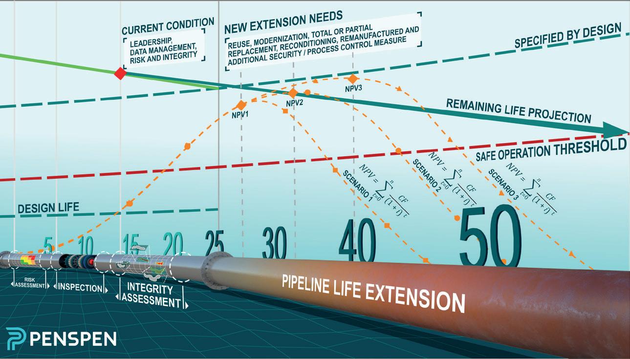
06. The stepping stones to life extension

Gustavo Adolfo Romero Urdaneta, LATAM Director at Penspen.
MATERIALS TECHNOLOGY
13. A new (virtual) reality
Michael Smith, ROSEN Group, UK.
SENSING 17. A buried solution Steve Strachan, Sensor Networks, Inc. 23. Groundbreaking pipeline insight
R. J. Pidcock, S. Blaney, B. Bilsbrough and E. Taylor, RSK Group, UK and E. Segal, Y. Lorig, ASTERRA, Israel.
SOFTWARE AND DATA MANAGEMENT 29. Dare to defer?
Christopher Blake, Head of New Business for IMRANDD.
INSPECTION
32. Rising to the unpiggable challenge Rod Lee, Pipetel Technologies Inc. (an Intero company).
35. Verifying integrity: a how to Peter Faulkner, Director of Market Development, Olympus Scientific Solutions Americas, USA.
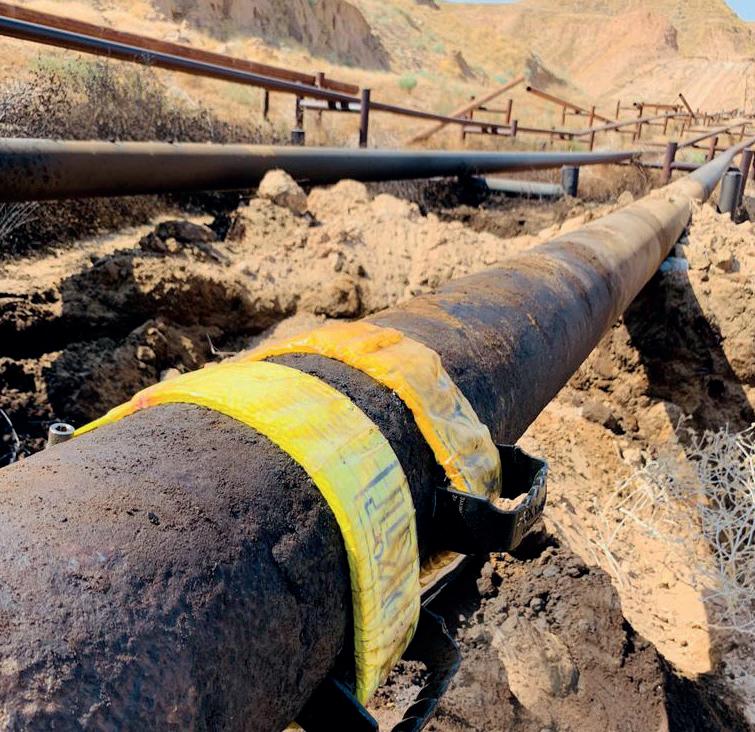
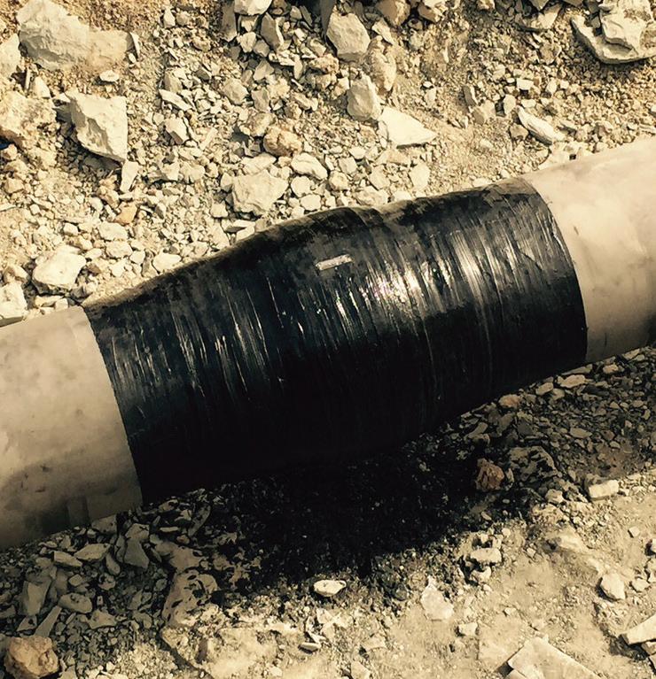
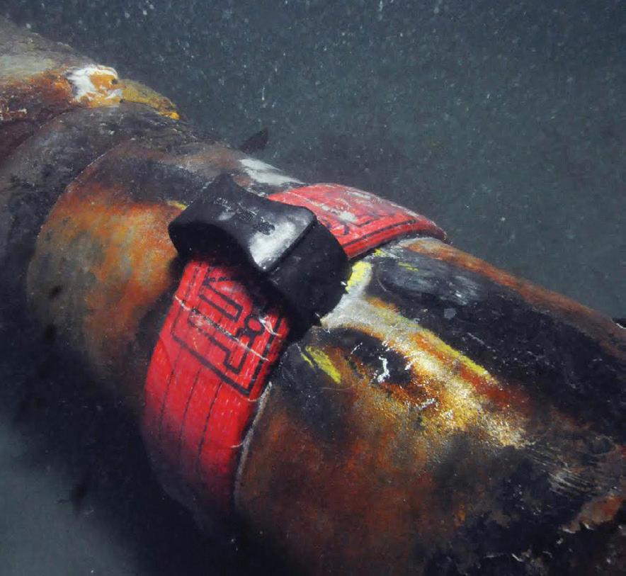
Group Germany is launching a patented, universally applicable new product, the SEALID® All-in-1 Tape. It provides, for the first time worldwide, protection against corrosion and mechanical stress in just one step, without an additional primer or equipment. SEALID® All-in-1 offers patented safety fulfilling ISO 21809-3 and EN 12068. Saving time and money has never been this simple. SEALID® All-in-1. Wrap once. All done.
Get ready for the impossible.
ON THIS MONTH'S COVER Member of ABC Audit Bureau of Circulations ISSN 14727390 Reader enquiries [www.worldpipelines.com] CBP006075 www.worldpipelines.com Get ready for the impossible. SEALID® All-in-1 Wrap once. All done. RZ_Titel_WorldPipelines_210916.qxp_003_Titel WorldPipelines-180831 17.09.21 15:48 Seite 1 WORLD PIPELINES COATINGS & CORROSION 2021 A SUPPLEMENT TO WORLD PIPELINES C O NTENTS Copyright© Palladian Publications Ltd 2021. All rights reserved. No part of this publication may be reproduced, stored in a retrieval system, or transmitted in any form or by any means, electronic, mechanical, photocopying, recording or otherwise, without the prior permission of the copyright owner. All views expressed in this journal are those of the respective contributors and are not necessarily the opinions of the publisher, neither do the publishers endorse any of the claims made in the articles or the advertisements. Printed in the UK.
DENSO
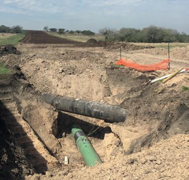
LATAM Director at Penspen, lays out pipeline life extension. context, optimising costs and resource utilisation by reuse through second operator. In addition, being able to process the results from an integrity study to conduct calculations the remaining life based on the growth of conditions, and no failures occur that generates adverse consequences. Impacts on human health and safety, the environment, reputation and finances such production losses, emergency care and recovery costs, 6 7 PAGE 32 Rod Lee, Pipetel Technologies Inc. (an Intero company) presents an overview of key milestones in Pipetel’s journey of providing certainty and safety to challenging and unpiggable pipelines around the world. A lthough Pipetel (which recently became an Intero member-funded organisation that focuses on technology research for the benefit of the natural gas industry and its customers the US. This article presents an overview of key and in. diameter pipes, in live natural gas pipe for testing. Further refinement over the next few years allowed to finesse the technology and commercialise the robot into service integrity management programme. In order to reduce risk and exposure to incidents, inline inspection provides the most comprehensive data develop safety programme that meets Unpiggable inspections and remote field eddy current sensor for detecting corrosion. That year, we inspected pipes for Canadian operator and US operator as well successfully completed our first ever, robotic inspect pipes in the diameters of 10, and 14 in. This was the first EXPLORER ILI robot featuring tri-axial sensing and high-resolution Magnetic Flux Leakage (MFL) sensor. The following year, due unpiggable pipes by providing the best visibility of imminent threats. EXPLORER ILI robots capture high quality, accuracy, and quantity of data for industry-leading operators to achieve 33 32 17 35 45 CORROSION 41. Protecting pipes during pullback Ron Raphoon, Denso North America. SUBSEA INSPECTION 45. Subsea technologies of the future Paul Chittenden, TSC Subsea. PAGE 41 Ron Raphoon, Denso North America, outlines key considerations for protecting pipeline coatings during trenchless T as easy as it sounds. The various soil layers beneath our feet contain wide variety of soil types, rocky layers, and random obstructions. While the drawings of an HDD are much like Figure (long, smooth, curving, and uniform), the reality that the hole can be filled with shards of 41
PAGE 06
STRUCTURAL POWER OIL & GAS
GUEST COMMENT
Bob Chalker Chief Executive Officer of the Association for Materials Protection and Performance (AMPP)

Corrosion is the predominant global threat to the integrity of pipelines that transmit dry gas, wet gas, crude oil and processed liquids. Oil and natural gas pipeline failures can cause injury, loss of life and significant harm to the environment.
According to a 2021 Pipeline Maintenance Services Market Report by Mordor Intelligence, corrosion control represents the largest percentage of a pipeline’s operational and maintenance costs worldwide. Over the next five years, stakeholders in the North Sea and Gulf of Mexico regions are expected to decommission and abandon a significant volume of pipelines. Within 30 years, the report estimates, more than 470 pipelines in the North Sea will require partial or complete removal, suggesting corrosion control services are vital to global pipeline safety and reliability.
To prevent the corrosion of natural gas, crude oil and processed liquid pipelines, companies pursue two principal approaches. They can apply protective coating systems to the pipe, and they can also implement cathodic protection, an electrochemical means of preventing and controlling corrosion.
Stakeholders who protect our global pipeline infrastructure using these approaches frequently depend on experts from the Association for Materials Protection and Performance (AMPP). AMPP’s membership includes global technical experts with experience developing and applying the most up-to-date corrosion prevention and control methods. One of AMPP’s key priorities is to help businesses and governments worldwide to create a proactive approach to corrosion control through corrosion management programmes.
Born from a merger between NACE International and SSPC in January 2021, AMPP has combined, within one global nonprofit organisation, 145 years of historical expertise in corrosion control and protective coatings, industry training, new standards development, and forums for exchanging best practices in corrosion control and management.
US policymakers tend to agree that America’s infrastructure needs more government investment and a greater emphasis on repair and maintenance. This year, AMPP’s legislative experts have been working to ensure that the bipartisan infrastructure legislation (now pending) prioritises corrosion control planning in all federally funded projects where corrosion threatens the long-term viability of an asset. The outcome of this legislation stands to serve as a template for AMPP’s public policy efforts worldwide.
In addition to implementing optimal coatings and cathodic protection technologies, energy companies are beginning to realise the benefits of long-term corrosion control planning, guided by strong communication between corrosion professionals and senior management. AMPP has created a suite of tools and examples, known as IMPACT PLUS, to help pipeline companies translate their coatings and corrosion control practices into the language of their broader organisations.
Practicing corrosion management to achieve pipeline integrity encompasses all activities that are performed through a structure’s lifetime to prevent corrosion, repair damage, and replace the asset itself.
Through its presence in 130 countries, AMPP provides services to 40 000 members in the areas of certification, accreditation, membership, advocacy and public affairs, standards, technical and research activities, conferences, events, education, training, publications and pre-professional programming. While AMPP’s coatings experts plan to meet this December at the Coatings+ Conference, the association’s full global membership will convene in San Antonio next March for the inaugural AMPP Annual Conference + Expo 2022. The entire AMPP community is committed to providing pipeline stakeholders with management and technical expertise necessary to integrate corrosion management practices into all levels of their organisations. The health and longevity of our global pipeline infrastructure depend on it.
COATINGS & CORROSION 2021 / World Pipelines 3
ENERGY COMPANIES ARE BEGINNING TO REALISE THE BENEFITS OF LONGTERM CORROSION CONTROL PLANNING
Global coverage of the downstream oil and gas sector


Subscribe online at: www.hydrocarbonengineering.com/subscribe

Worldwide Coverage
COMMENT
CONTACT INFO
MANAGING EDITOR James Little james.little@palladianpublications.com
ASSISTANT EDITOR Aimee Knight aimee.knight@palladianpublications.com
SALES DIRECTOR Rod Hardy rod.hardy@palladianpublications.com
SALES MANAGER Chris Lethbridge chris.lethbridge@palladianpublications.com
DEPUTY SALES MANAGER Will Pownall will.pownall@palladianpublications.co
PRODUCTION Calli Fabian calli.fabian@palladianpublications.com
DIGITAL EVENTS CO-ORDINATOR Louise Cameron louise.cameron@palladianpublications.com

DIGITAL ADMINISTRATOR Lauren Fox lauren.fox@palladianpublications.com
VIDEO CONTENT ASSISTANT Molly Bryant molly.bryant@palladianpublications.com
ADMIN MANAGER Laura White laura.white@palladianpublications.com
Palladian Publications Ltd, 15 South Street, Farnham, Surrey, GU9 7QU, UK
Tel: +44 (0) 1252 718 999 Fax: +44 (0) 1252 718 992 Website: www.worldpipelines.com
Email: enquiries@worldpipelines.com
Annual subscription £60 UK including postage/£75 overseas (postage airmail). Special two year discounted rate: £96 UK including postage/£120 overseas (postage airmail). Claims for non receipt of issues must be made within three months of publication of the issue or they will not be honoured without charge.
Applicable only to USA & Canada: World Pipelines (ISSN No: 1472-7390, USPS No: 020-988) is published monthly by Palladian Publications Ltd, GBR and distributed in the USA by Asendia USA, 17B S Middlesex Ave, Monroe NJ 08831. Periodicals postage paid New Brunswick, NJ and additional mailing offices. POSTMASTER: send address changes to World Pipelines, 701C Ashland Ave, Folcroft PA 19032
Ben and Jerry brought us cookie dough in an ice cream tub. Larry and Sergey gave us Google. John and Paul changed the face of popular music in the 1960s. A collaboration can be a wonderful thing. Here’s a few from the energy space that have caught my attention recently.
DNV and Wintershall will work together to carry out the world’s first large-scale testing of submerged CO2 pipelines, and together they’ll explore how best to repurpose subsea natural gas pipelines in the southern North Sea for future CO2 transport. Staying offshore, OPITO (the global safety and skills body for the energy industry) has signed an MoU with the Acorn Project and Scottish Cluster, to jointly develop a blueprint of industrial skilling and reskilling training for the low carbon economy. The Acorn Project (developed by Storegga in partnership with Shell UK and Harbour Energy) works on carbon capture and storage (CCS) and hydrogen projects, including using existing offshore gas pipelines to provide access to CO2 storage located in rock formations deep under the North Sea.
DNV and Equinor are partnering to develop software for safe CCS. The collaboration focuses on developing consequence models for safety assessment, design of barriers and documentation of CCS safe design, including tools to simulate what happens if an accident were to occur.
Also offshore – and in response to a rise in demand for AUV pipeline inspections around the globe – Ocean Floor Geophysics Inc. and DOF Subsea AS have formed a strategic alliance for global AUV services, which builds on their recent collaboration for the development of an AUV non-contact integrated cathodic protection system and which will enable the sharing of resources on pipeline inspection and geohazard surveys.
McDermott and Shell are collaborating with the aim of decarbonising construction: through pathways such as low carbon fuels, renewable power, digital solutions and decarbonising marine construction vessels, they will explore opportunities for reducing and eliminating emissions from construction.
Endress+Hauser and the International Society of Automation (ISA) have announced their current and future collaboration efforts for training and certification. ISA will provide certified training courses in conjunction with Endress+Hauser’s courses, offering guidance for instrument technicians across the US.
Also in the US, Lincoln Electric and Stress Engineering Services, Inc. (SES) have formalised their collaboration in large-format metal additive manufacturing (AM). By combining their AM expertise, they hope to enhance design, analysis, and validation testing, encouraging greater adoption of the technology in the oil and gas sector.
Baker Hughes and Primus Line are to collaborate on non-metallic composite pipe applications to rehabilitate and repurpose existing pressure pipelines. The partnership will offer customers more options for pipeline repair and replacement, as well as the repurposing of existing pipeline networks for hydrogen and CO2 transportation.
In the cyber arena, DNV and Applied Risk are joining forces to create the world’s largest industrial cyber security practice, to defend critical infrastructure in energy and other sectors.
Of course, the corrosion industry saw a major collaboration at the beginning of this year. The merger of NACE International and SSPC formed the Association for Materials Protection and Performance (AMPP) and I’m delighted that Bob Chalker, AMPP’s CEO, is providing the guest comment for this special issue of World Pipelines
SENIOR EDITOR Elizabeth Corner elizabeth.corner@palladianpublications.com
ow do you justify the operation of pipelines beyond their design life? There are many reasons. For example, increasing the life of the production field, changes in the operational context, or optimising costs and resource utilisation by reuse through a second operator. In addition, being able to process the results from an integrity study to conduct calculations of the remaining life based on the growth of time-dependent defects are other important factors, to name a few. Operating beyond the design life can be done if the pipelines are within a safe operating range for their estimated lifetime and required operating conditions, and if no failures occur that generates adverse consequences. Impacts on human health and safety, the environment, reputation and finances such as production losses, emergency care and recovery costs, are all important considerations. Life extension has become an increasingly attractive option to avoid decommissioning assets, which is a costly and logistically
 Gustavo Adolfo Romero Urdaneta, LATAM Director at Penspen, lays out a guide to the essential steps of formal pipeline life extension.
6

7
complicated process. Furthermore, due to the decrease in oil and gas prices, new projects have been postponed or cancelled, which also leads operators to try to keep their assets operating for as long as possible.
For years, the result of the remaining life calculated from integrity projections has been used as justification for extending the life of assets beyond the design life, complemented by a plan of operation (operating within specified limits) and maintenance activities performed during the required life (cathodic protection, coatings, supports, direct and indirect inspections, patrolling, leak barriers, among other activities), to safely guarantee this life extension and refreshing of staff competencies. Despite this, failures unfortunately continue to occur in ageing pipelines that are operating within the remaining life threshold. This is a consequence of inadequate integrity assessment and/or not completing complementary integrity and reliability assurance activities. This can be due to budget, organisational changes, untrained personnel or inadequate change management, combined with the lack of a formal asset integrity management system that includes a process for life extension. API 579 Fitness-For-Service Evaluation states that the remaining life calculated using correlations and defect growth projections obtained during inspections can be used to define appropriate inspection intervals, mitigation, monitoring activities, and remediation needs, and not to provide an estimate of actual time to the failure. This means that in addition to the current integrity condition and remaining life projections, the life extension of a pipeline requires a system to manage the life extension process in a safe, reliable, and cost-effective way within the time required by the organisation and its stakeholders.
Best-in-class operators have already established and developed their pipeline integrity management systems (PIMS) with several cycles of audits, allowing them to maintain the process of continuous improvement of their systems. However, the ageing of pipelines and the process to be implemented when a lifetime extension is required is not included as a formal process in the integrity management system (IMS). At the same time, many regulators have not
included the specific requirements that pipeline operators have to comply with when they require life extension, but it is implicit in the paragraphs and items of the rules that require the operator to ensure the integrity and reliability of the pipelines from the start of operation until its abandonment. In addition, the costs for insurance premiums or bonds increase when the pipelines have a low life expectation versus pipelines with an extended life plan.
Background
Although ageing asset management is a topic that has been discussed for years, in this article we will focus on the last 10 years and the relevant background regarding the advances and recommendations resulting from the initiatives of government entities, such as the UK and Norway, followed by technical committees of experts, which have helped to create a basis for the life extension of assets. Notable programmes and publications include:
) Between 2010 and 2013, the UK Energy Division of the Health and Safety Executive (HSE), conducted audits of onshore and offshore assets to review their integrity management systems and asset life extension processes, in order to determine if risks were being managed effectively and to encourage the process of continuous improvement. From these audits, HSE published a report called KP4 (Key Programme 4) in which they indicate that the age of the installation is not necessarily a reliable indicator of the condition or likelihood of the frequency of hydrocarbon leakage but should be referred to other factors such as: leadership and knowledge of the life extension process, the relationship with asset integrity management, obsolescence, audits and monitoring of indicators and data management.
) In 2013, the ISO/TC 67/SC 2 technical committee responsible for discussing the life extension of pipelines noted that operators are applying different approaches to life extension, leading to the inefficient use of resources by both the operator and the authority. Therefore, the Recommended Practice published by the British Standards Institution (BSI) for Life Extension of ISO/TS 12747 Pipelines was updated in 2013, providing guidance for assessing the feasibility of extending the service life of a (rigid metallic) pipeline system beyond its specified design life. This RP refers to life extension as a modification to the original design without including reclassifications of the maximum allowable operating pressure (MAOP).
) In 2017, after more than 10 years working on and publishing documents related to the life extension of assets, the Norwegian Oil and Gas Association revised and published the document 122 - Recommended Guidance for Life Extension Management, to establish guidelines for operators who have won
8 World Pipelines / COATINGS & CORROSION 2021
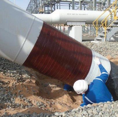
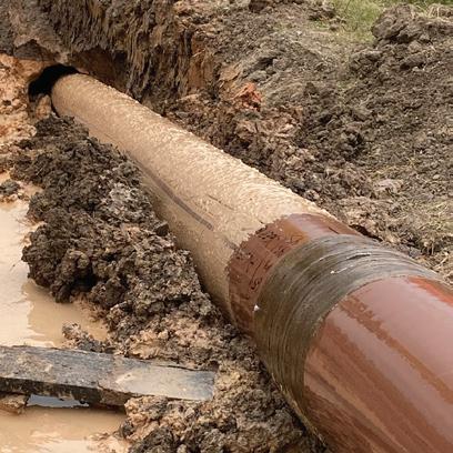
Figure 1. Illustrative diagram of pipeline life extension.
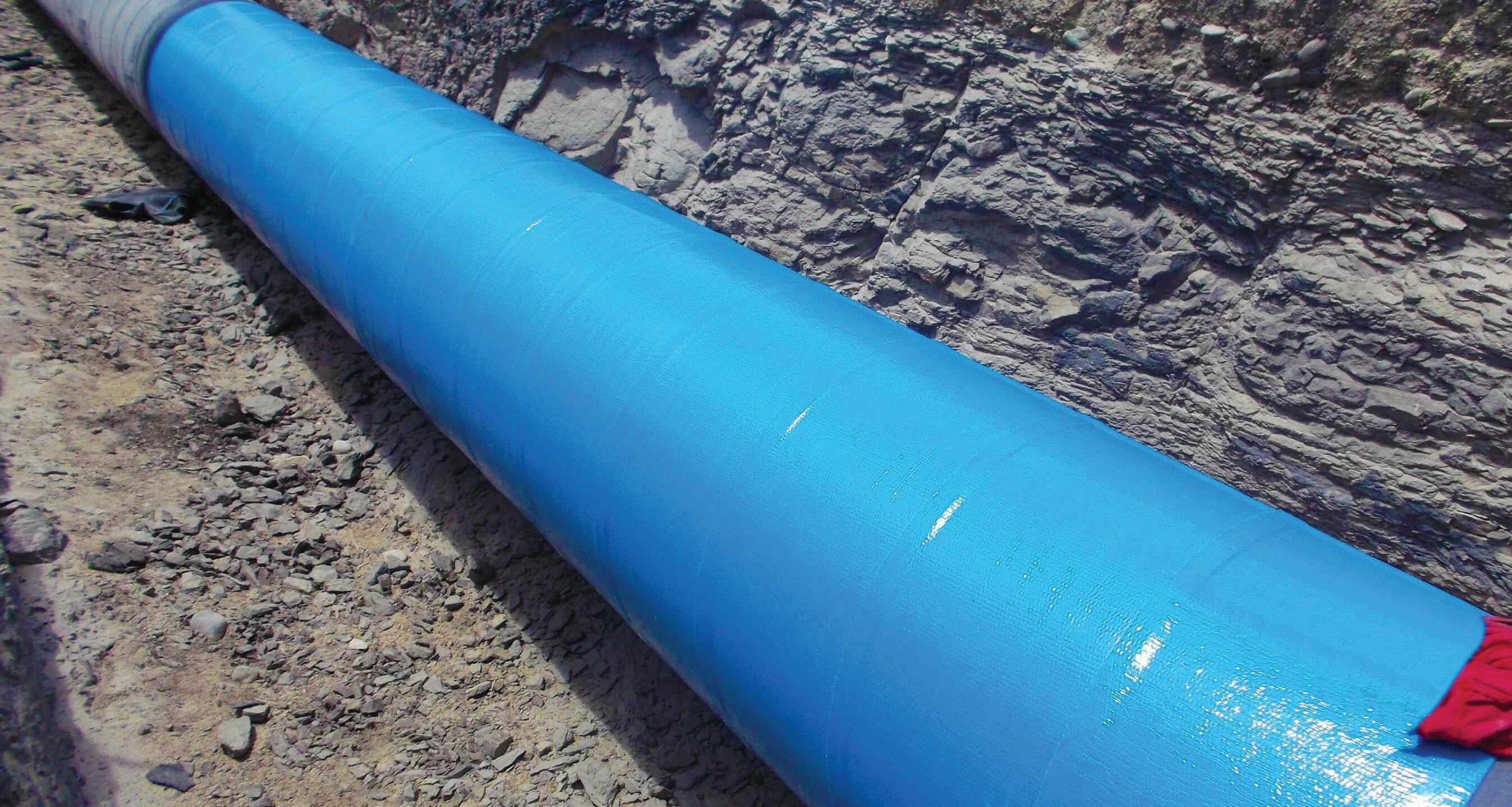
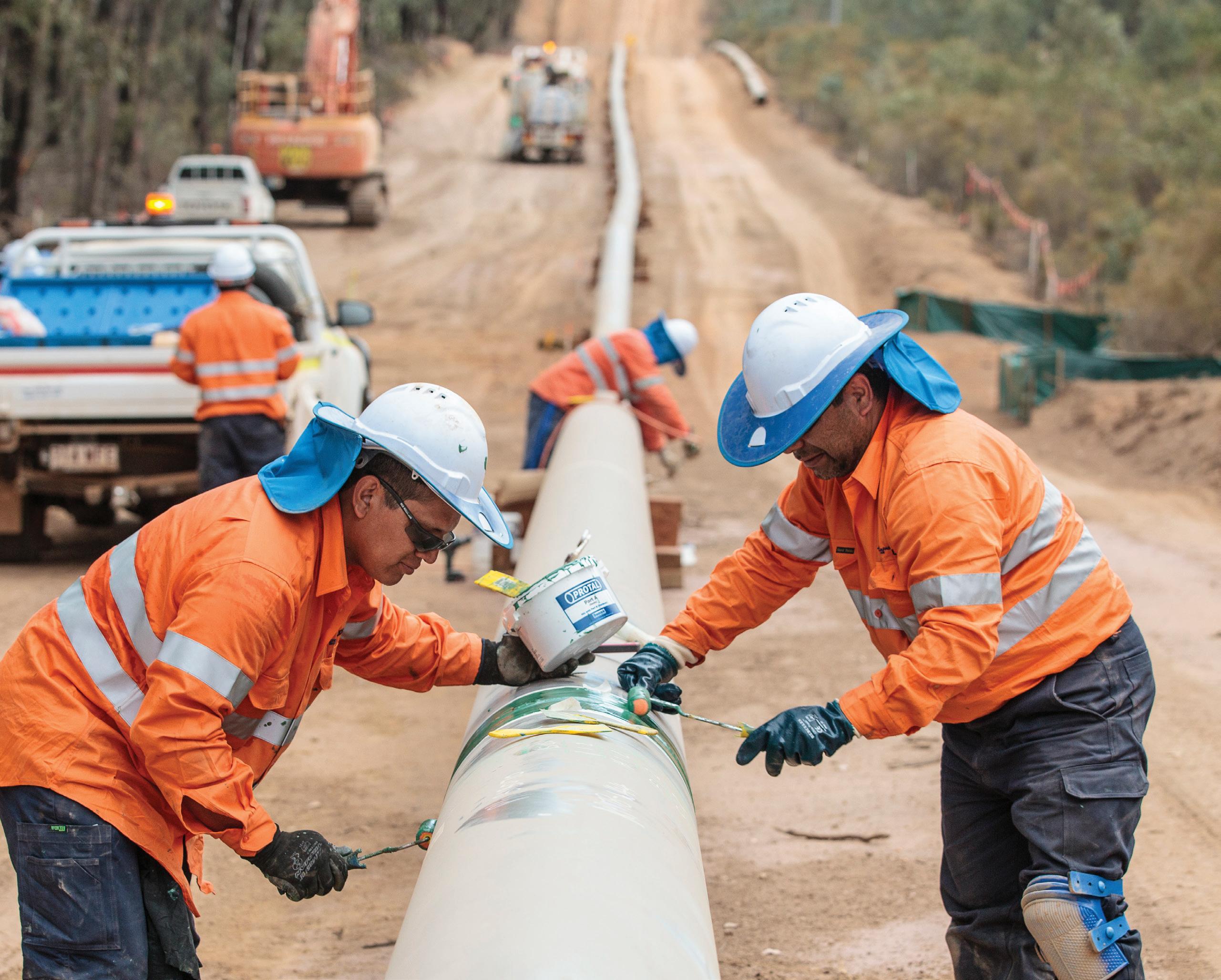
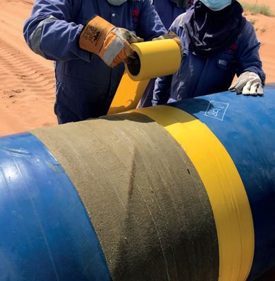
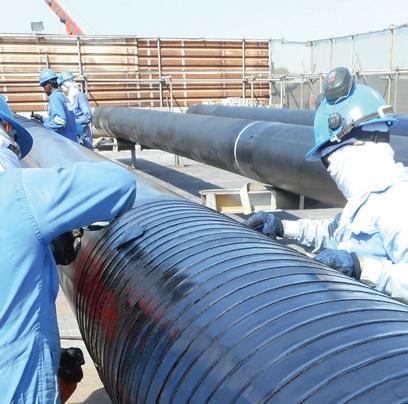
PROTECTIVE OUTERWRAPS SOIL-TO-AIR INTERFACE SYSTEMS BITUMEN & BUTYL TAPES PETROLATUM TAPE SYSTEMS PROTAL 7200™ SPRAY/ROLLER/BRUSH APPLIED LIQUID EPOXY COATING DENSO VISCOTAQ™ FOR CORROSION PREVENTION DENSO™ are leaders in corrosion prevention and sealing technology. With over 135 year’s service to industry, our mainline and field joint coating solutions offer reliable and cost effective protection for buried pipelines worldwide. United Kingdom, UAE & India USA & Canada Australia & New Zealand Republic of South Africa www.denso.net www.densona.com www.densoaustralia.com.au www.denso.co.za A MEMBER OF WINN & COALES INTERNATIONAL A range of viscoelastic tapes used for corrosion prevention on pipelines, field joints, fittings & valves. The unique, self-healing technology of Viscotaq offers asset owners outstanding, long-term protection against corrosion. > >
production licences for fields. This guidance states that two levels should be considered: a first level that focuses on the asset and includes the design life, required life and the need for extension; and a second level that involves the system where the assessments and methodologies for life extension are considered.
) Norway and the UK have already incorporated specific requirements in their regulations to ensure that pipeline operators can continue operating beyond the design life through life extension management as an element of the IMS. In Norway, it is mandatory to obtain the consent of the regulatory body before extending the useful life of an asset. In the UK, the body regulator sees this life extension as a significant change in the “Safety Case”.
) In late 2020, NOPSEMA (Australia’s Offshore Energy Regulator) published a guide to promote the industry’s practices to ensure that the risks associated with ageing assets are managed at ranges as low as reasonably practicable (ALARP) in a legislative context of the Offshore Oil and Gas Greenhouse Gas Safety Act. The age profile of installations in Australia is similar to those
in the North Sea, ranging from four years to over 50 years.
) In America, in recent years, countries such as Canada have also begun to incorporate some requirements related to life extension as a process that can be audited through evidence of its effectiveness and follow-up activities. In 2019, the world-class independent regulator C-NLOPB (Canada-Newfoundland and Labrador Offshore Petroleum Board) developed a guide to provide additional information and guidance to facility operators on the steps and phases to consider when assessing a Life Extension Plan to maintain the compliance with the regulatory requirements, as well as to ensure that the assets are properly managed and that the necessary improvements are identified and implemented. In Latin America, the regulations do not set out specific requirements to ensure the safe operation of a pipeline when its lifetime is required to be extended beyond the original design, but rather leave it implicit when they state that the operator shall ensure that pipelines operate safely throughout their lifetime.
10 World Pipelines / COATINGS & CORROSION 2021
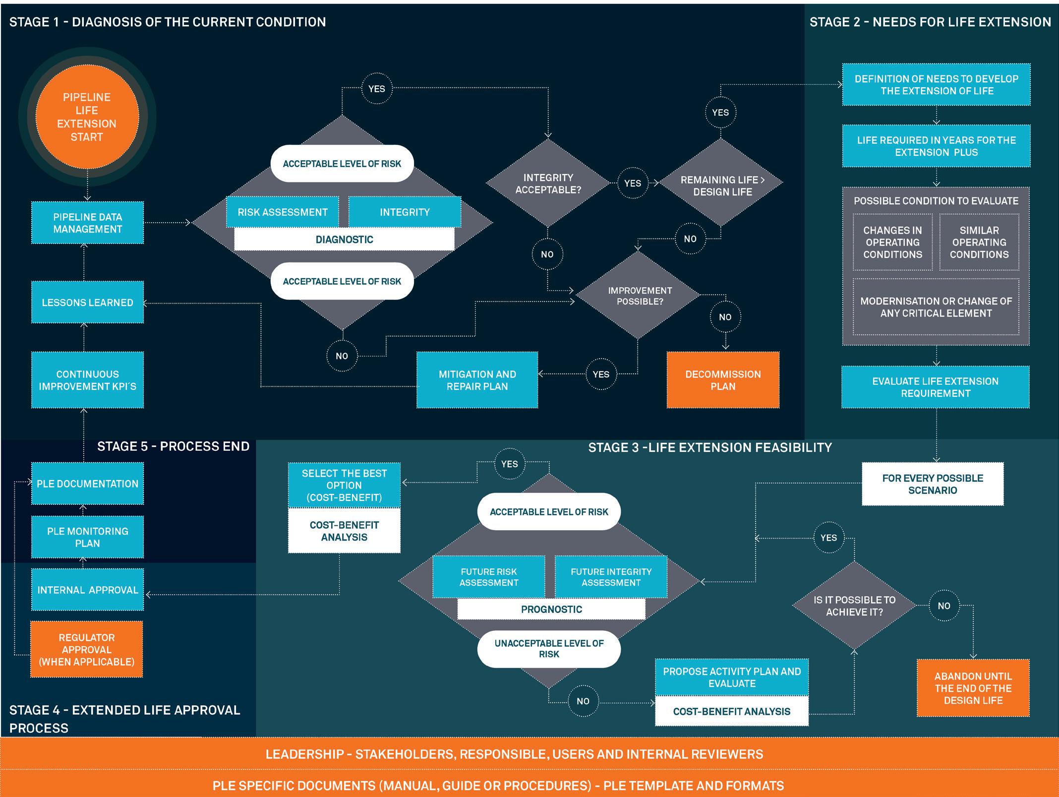
Figure 2. Pipeline life extension (PLE) process.
State-of-the-art
Today, after some years of work and efforts to promote the life extension process as a key element in pipeline integrity management, it is clear that there is still a long way to go, especially in countries where it is not yet mandatory to have a clearly documented life extension process and where the risk of failures continues to grow due to the increasing number of ageing pipelines operating beyond their original design life. For this reason, this article intends to serve as a guide for pipeline operators, regulatory bodies and technical organisations that are interested in knowing a little more about the essential steps required when a formal pipeline life extension process needs to be implemented. The life extension process is an essential part of the PIMS when there are ageing pipelines or when it is required to extend the service life beyond the design life. The success of this process is based on a first level focused on the system that involves the availability of leadership, strategic planning, and information management (storage, visualisation, and digital tools), analysis, monitoring and detection of improvements, and a second level directly related to the studies and activities required to assess the feasibility of the life extension of each pipeline. Figure 2 is a step-bystep flowchart for the implementation of a pipeline life extension process, complemented by the following brief description of each stage.
Stages of the pipeline life extension implementation process
Stage 0: Application for a pipeline life extension
All life extension processes are initially identified at the corporate level as part of the organisation’s strategic plan. Experience indicates that the life extension should be initiated between two to five years before the design life is exceeded. The decision to extend the life of a pipeline cannot be implemented by the technical or operational area alone but must be part of the strategic needs of the organisation at the corporate level. Future plans are established in terms of requirements for demand or changes required to increase or expand the profitability of the business, involving the analysis of the operational costs and investment costs.
During the strategic planning, it is identified whether it is necessary to extend the useful life of any of the pipelines in order to achieve the owners’ and/or stakeholders’ proposed goals, which may include reuse, modernisation, full or partial replacement, refurbishment, remanufacturing and additional safety/process control measures. Sometimes it is necessary with the entry of new investors, who will ask about extension options as a strategy for optimising resources and recovering their investment.
Stage 1: Diagnosis of the current condition
There is a consensus that any life extension proposal should start with an initial diagnosis, including a review of the organisation, document management and assessment of
the current condition of the pipeline, based on the results of inspection with instrumented tools or through direct assessments whose origin was defined from:
) Risk analysis where the probability of failure due to specific hazards and the consequences that can be generated in each case are defined. This triggers the inspection plan and some risk mitigation activities.
) Integrity assessment that determines the MAOP for each defect, using the recommendations of the Defect Assessment Manual (PDAM) and the remaining lifetime, using probabilistic defect growth models and cycle counting when it is additionally required to assess the fatigue phenomenon.
) Additionally, the activities necessary to recover or maintain the required integrity and risk for the time set by the operator are identified.
Note: the more information that exists on the condition of the pipeline, the more certain the predictions and possible scenarios for life extension will be.
Stage 2: Life extension needs
Once it is confirmed that the pipeline has an acceptable risk and sufficient remaining life under its current conditions to assess the feasibility of life extension, it is determined the specific needs that the operator requires to extend the life of the pipeline safely and reliably. Extending the time beyond the design life (reuse) and keeping the operating conditions within the permitted ranges is normally one of the most common needs; however, it may also include a change in operating conditions (reclassification), as, for example, modification of the flow rate and fluid handled, maximum operating pressure and/or temperature, among others.
In some cases, a change of location, class and/or compliance with new regulatory requirements that would apply during the extension may also be requested. A piping system also includes other elements and fittings in addition to the pipeline sections, which may also require an independent feasibility assessment to confirm their reliability or to identify that they require modifications and/ or upgrades.
Stage 3: Feasibility of the life extension
Although pipeline extension is normally the most attractive alternative, a business case or cost benefit study is required that includes, for example, capital expenditure, installation, operation, maintenance, and risk. The Net Present Value (NPV) cost-effectiveness indicator has often been used to determine the most appropriate option by comparing the mitigation cost necessary to achieve the desired life extension with the cost of a new pipeline or replacement of any of its sections and/or parts, and the profitability and revenue for the required extension period. For each alternative proposed as a solution to the life
COATINGS & CORROSION 2021 / World Pipelines 11
extension needs, a new risk study should be performed that considers the new scenarios and conditions, with an integrity assessment that simulates and projects the growth of defects under the expected conditions to determine whether the pipeline can achieve the life required by the requested extension process.


It is important to note that the justification for the life extension of a pipeline may also include external and intangible benefits in terms of its benefit to, for example, a community in terms of supplying some energy demand. In some cases, the result may suggest that it is not possible to extend the life and that the most viable option will be the construction of a new pipeline.
Stage 4: Life extension approval
Once it is confirmed that the pipeline can be extended beyond its design life in accordance with one of the scenarios that showed the best cost-benefit, a document is created in which the justification, plan of activities required for implementation and plan of monitoring activities to ensure the integrity and risk during the extension of the pipeline’s life is established. Finally, the document must be signed as evidence of approval by the working team assigned by the company for the extension process and senior management.
Step 5: Closure and documentation of the process
All information created during the extension process shall be included and stored as part of the IMS in a specific section for life extension. In countries where the regulator requests specific compliance requirements, the operator shall ensure that these are included in the proposed documentation and activities. It is recommended to include performance indicators to monitor the implementation of the extension. Some operators keep a record of their ageing assets and the percentage that are operating beyond their design life as a way of classifying their assets and at the same time their condition indicator.
Bibliography
Y-002 Life Extension For Transportation Systems. Norsok Standard (2010). Key Pro gramme 4 (KP4) Ageing and life extension programme Energy Division of HSE’s. Hazardous Installations Directorate (2013). www.hse.gov.uk/offshore/ageing.html PD CEN ISO/TS 12747:2013. Petroleum and Natural Gas Industries – Pipeline Transportation System – Recommendeed Practice for Pipeline Life Extension (2013). API 579-1/ASME FFS-1. Fitness-For-Service (2016).
PDAM Joint Industry Project. Pipeline Defect Assessment Manual. Penspen (2016). 122 - Norwegian Oil and Gas Recommended Guidelines for the Management of Life Extension. Norwegian Oil and Gas Association (2017).
Selection of the most suitable life extension strategy for ageing offshore assets using a life-cycle cost-benefit analysis approach. Journal of Quality Maintenance Engineering. Vol 24. Issue: 3. I. Animah, M. Shafiee, N. Simms, J. Ahmet, J. Maiti. (2018).


C-NLOPB Asset Design Life Extension Program Guideline for Offshore Canada Newfoundland and Labrador (2019).

Pipeline Integrity Management System (PIMS). Penspen Model, Penspen (2019). Penspen Asset Life Extension methodology. Penspen (2020). UKOPA/GP/018. Good Practice Guide Remaining Life Assessment (2020).

THE FUTURE OF CORROSION PREVENTION
Introducing AMPP, the Association for Materials Protection and Performance. After more than 70 years, NACE International and SSPC have united as the global authority for corrosion prevention knowledge. We are creating the future of materials protection and performance and leading the way for the industries we represent. AMPP members protect people and places around the world from corrosion, and together we are building a safer, protected, and preserved world.

Learn
www.ampp.org
more about AMPP.
Advances in inline inspection (ILI) technology have almost always been driven by improvements to hardware components such as magnets, transducers, sensors and batteries, or the software that converts sensor data into anomaly measurements. The next great leap in inspection technology will, however, have very little to do with hardware and sensor data. In fact, the next generation of inspection ‘tools’ will have none of these things at all.
Virtual ILI offers the promise of establishing a pipeline’s condition without having to think about the constraints of location, flowrate, tight bends, valves or tees, or any of the other features that traditionally create obstacles for an ILI tool.
Why? Because there is no ILI tool – at least not in the conventional sense. Instead, virtual ILI is an entirely digital inspection that relies on supervised machine learning in order to generate its ‘measurements’.

Supervised machine learning
A commonality across many industries is the need to quantify relationships between variables and formalise these relationships within predictive models. We may want to model, for example, how world events affect the stock market, how nutritional choices influence heart health, or how demographic information influences which TV series or movies a user might enjoy.
Michael Smith, ROSEN Group, UK, describes the development of an entirely digital inline inspection method.
13
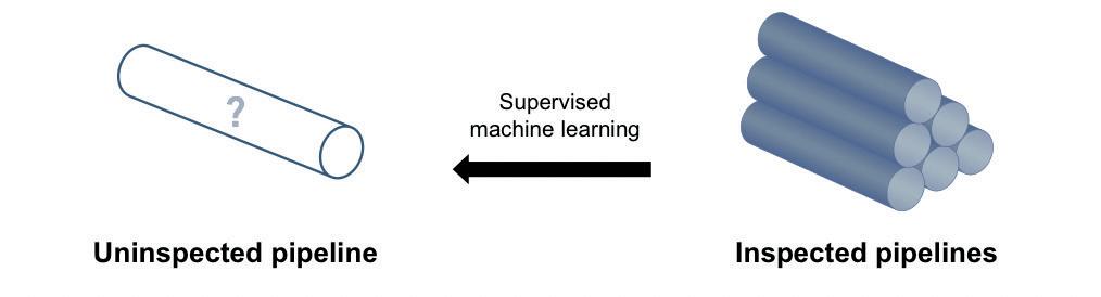
Figure 1. Principle of virtual ILI.
Figure 2. Contents of the integrity data warehouse.
In each of these cases, the relationship between the predictor variables (e.g. age, gender, native language) and target variable (e.g. favorite sci-fi epic) can be expressed using a function, f. For multiple predictor variables (x1, x2…xn), and a single target variable (y) we can write:
y = f(x1, x2…xn)
With enough historical data (i.e. examples of previous cases) the function f can be approximated and used to make predictions for unseen cases.
This is the principle of supervised machine learning, and it is exactly how virtual ILI works. With enough examples of inspected pipelines, we can identify trends between pipeline characteristics and pipeline condition, and embed these trends within predictive models (Figure 1). We can then deploy these models as a digital alternative to ILI.
Integrity data warehouse (IDW)
In order to create meaningful predictive models, we need a relevant and reliable dataset of examples.
The integrity data warehouse, or IDW, is ROSEN’s global repository of ILI results and integrity management information. At the time of this writing, the IDW contains results from almost 15 000 inspections, in addition to design, construction, environmental and operational information for around 10 000 inspected pipelines (Figure 2).
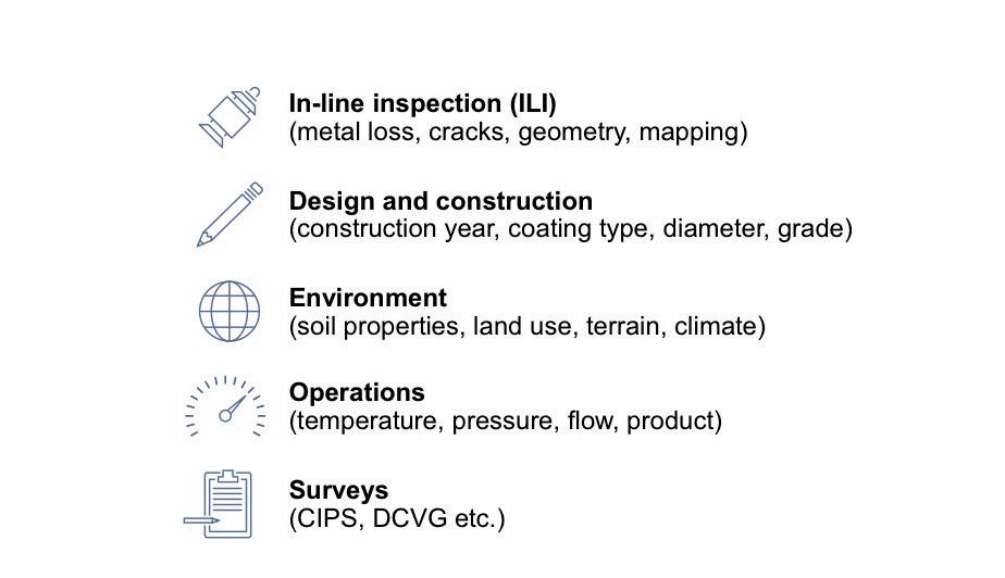
The IDW is still being developed and is estimated to be less than 50% complete, but with a total inspected length exceeding 20 times the circumference of the Earth, the data already offer a rich feedstock for predictive modelling.
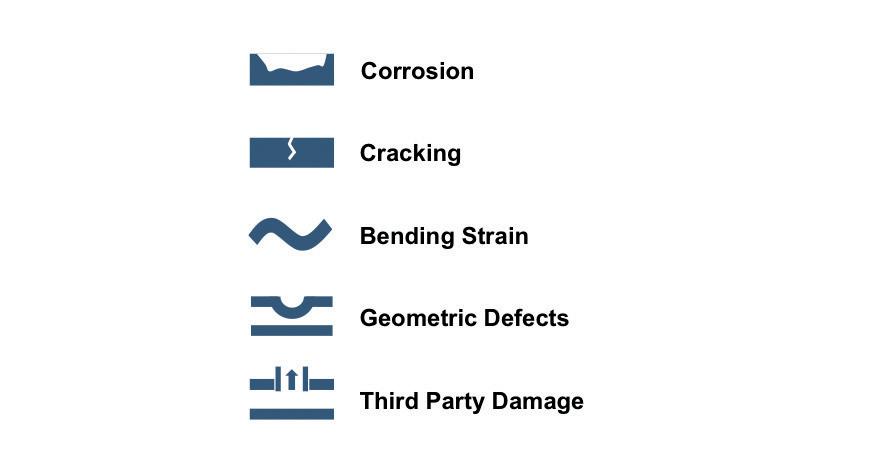
Models can be created for many different pipeline threats (Figure 3), but ROSEN’s most advanced virtual ILI technologies – owing to the quantity, availability and accuracy of historical data – are trained for corrosion prediction.
Figure 3. Pipeline threats.
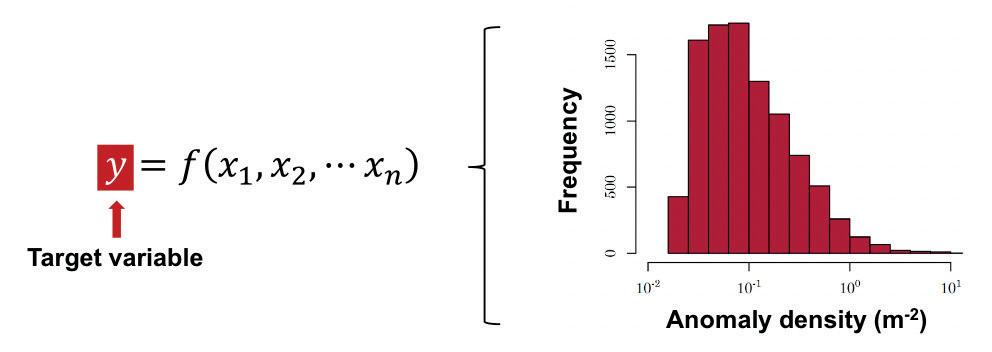
Figure 4. Anomaly density as a target variable for external corrosion prediction.
External corrosion prediction
ROSEN’s virtual ILI service for external corrosion prediction can be used to generate corrosion predictions for full pipelines, smaller pipeline segments or even individual pipe joints.
Whereas a real ILI will report a list of anomalies within a pipeline segment, virtual ILI estimates condition metrics. Condition metrics are single-valued, numerical descriptors representing unique aspects of pipeline condition. Examples include anomaly density (the number of anomalies per unit area) and maximum depth (the maximum anomaly depth within the segment). Each condition metric reflects a slightly different aspect of corrosion. For example, anomaly density represents the quantity of corrosion within a segment, while maximum depth represents severity.
In the language of supervised machine learning, these condition metrics are target variables for the models (Figure 4).
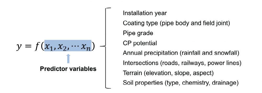
Figure 5. Predictor variables for external corrosion prediction.
On the other side of the equation are the predictor variables. These are characteristics of the pipeline segment that may influence (or at least correlate with) external corrosion (Figure 5).
14 World Pipelines / COATINGS & CORROSION 2021


Corrosive plus mechanical protection in just one step. Without any primer. Only SEALID® All-in-1 Tape makes it possible. Patented safety fulfilling ISO 21809-3 and EN 12068. Saving time and money has never been this simple sealid.de SEALID® All-in-1 Wrap once. All done. SEALID® All-in-1 Get ready for the impossible.
Figure 6. Open-source environmental datasets for the United Kingdom – from left to right, soil type, elevation, land use and precipitation.
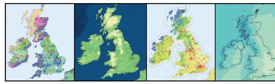
inspected pipelines, so that it can learn to identify trends. Does anomaly density increase as pipelines get older? Does it decrease for pipelines with more modern coatings? What happens when rainfall is high? What about the influence of soil type? In this respect the models make use of a wealth of open-source environmental datasets containing valuable information on soil types and chemistries, elevation, land use, and precipitation (Figure 6), as well as the locations of roads, railways, water bodies and power lines.
Once trained, the virtual ILI model is capable of taking a list of characteristics and returning an estimate of the target variable – such as anomaly density (Figure 7). But is it accurate?
Figure 7. Virtual ILI for anomaly density (anomalies m-2) prediction at pipe joint resolution.
Clearly, a virtual ILI cannot surpass the accuracy of a real ILI under optimal conditions, but when we test the models on an unseen sample of pipelines (i.e. pipelines that were not used to train the model), the performance is strong. This is exemplified in Figure 8, which shows anomaly density predictions for pipe joints within several hundred unseen pipelines around the world.
In Figure 8, more than 99% of anomaly density values are predicted within ±1 order of magnitude of the true (ILI) value – an enviable performance when compared to traditional modelling techniques for uninspected pipelines. Anomaly severity can also be predicted with a high level of confidence. This shows that the complex beast of external corrosion prediction can in fact be tamed. The pipe joint level of detail means that useful choices can be made regarding future actions.
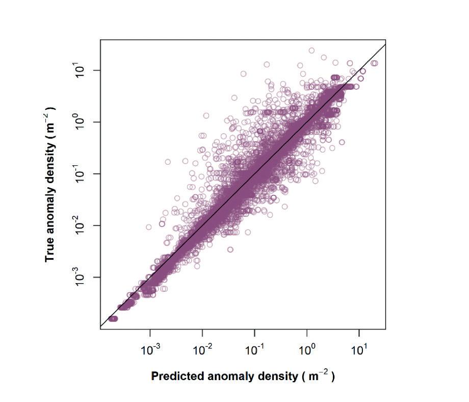
Nevertheless, outliers are an inevitability in early machine learning applications, and virtual ILI is no exception. Figure 8 shows some significant under- and over-estimates of anomaly density. They are relatively rare, but still problematic.
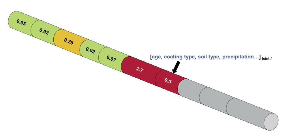
Figure 8. Predicted anomaly density (virtual ILI) vs. true anomaly density (real ILI) per pipe joint.
Predictor variables can be related to design and construction (such as age, coating type and pipe grade), cathodic protection, or even the local environment.
Once the target and predictor variables are defined, the model can be trained. This means showing the model as many examples as possible of historical corrosion, as detected by real inspections. In the case of external corrosion prediction, the models are trained using more than 100 million metal loss anomalies detected over the past 20 years.
In addition to the condition metrics, the model must see the characteristics (predictor variables) for the
In the case of corrosion prediction, these outliers are most likely caused by unique corrosion processes that the model has never seen, or by ‘hidden’ variables that are not currently captured in the models. This serves to highlight the importance of continuous improvement. Virtual ILI must continuously improve as new ILI datasets become available and new predictor variables are collected.
Over time, more and more of these rogue predictions will be brought into line, and the already excellent performance will further improve. It also shows that the role of the subject matter expert remains critical. An expert review of the results can identify cases with unexpectedly low or high anomaly density or severity, reducing the potential for significant errors.
We already know the power of ILI for integrity management of pipelines, and virtual ILI may be the next best thing.
The results from virtual ILI promise to be an excellent basis for quantitative risk and integrity assessments, allowing decisions on mitigation, rehabilitation and future monitoring to be made with more confidence than ever before.
16 World Pipelines / COATINGS & CORROSION 2021
Many asset owners/operators struggle to identify the cause of fluctuating corrosion rates due to unreliable or infrequent data. Midstream groups around the world are tasked with monitoring thousands of miles of pipelines using this same data. Many times, the only data these teams have to rely on are inspection reports from ILI (inline inspection) and NDE (non-destructive examination) techniques such as manual ultrasonic testing and/or radiographs. While these techniques can provide valuable ‘snapshots’ of the condition of locations, limitations and inherent error with these techniques can compound, leading to ill-advised decision making.
ILIs (pigging) are long-range non-destructive mass screening techniques performed periodically (and as spread out as possible) due to the cost of the process and downtime of the assets. When an ILI is performed (using a smart pig with ultrasound, MFL (magnetic flux leakage), etc.) and anomalies are found, a direct assessment (or dig) must take place at each of the locations under question. After a couple of days of excavation and prepping, a technician is sent into the hole to take manual ultrasonic thickness data to compare with the ILI. Depending on a host of different variables, the operator must decide between two options:
) The pipeline is fit for continued service as is and can be buried (perhaps instead of a seven-year ILI interval, a five-year interval will be required due to the wall thinning and unknown general corrosion rate).

) The segment under investigation is fixed, sleeved, or repaired (now the same inspection interval is granted because the remediation had taken place).
In either case, these are expensive propositions. Moving from a seven to five-year inspection interval could mean hundreds of thousands or millions of dollars of extra costs associated with ILI over the useful life of that segment of pipeline. Electing to fix,
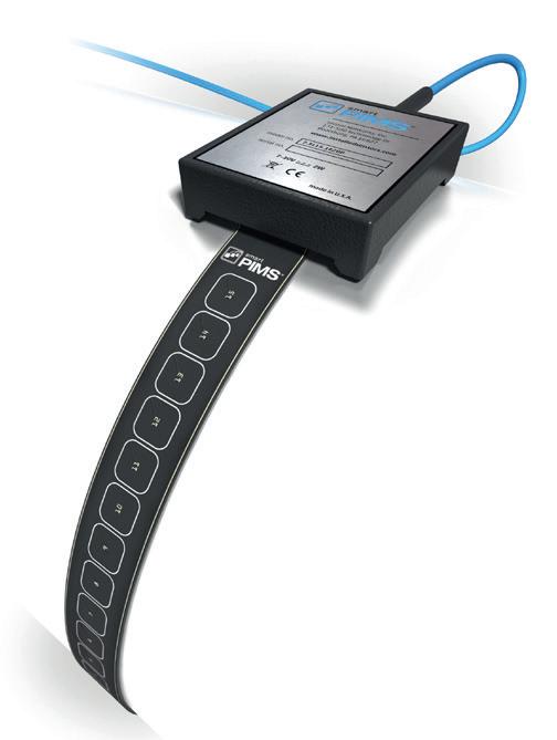
Steve Strachan, Sensor Networks, Inc., explains how midstream operators can harness the power of installed buried ultrasonic corrosion monitoring.
17
sleeve, or repair means additional costs in downtime, materials, labour, and inspection.
Until recently, these were the only two options for owners/ operators. Today, many are opting for a third option which allows them to continue operating on their normal inspection interval even when anomalies are identified, without having to take immediate remediation. Why? Because they are electing to monitor these locations using buried ultrasonic sensors.
In this third option, the workflow is simple; perform ILI, execute a direct assessment, mark locations under question, decide which ones to install sensors to monitor, and bury. When it is time to report the ILI findings and there are anomalies present, the regulating body will ask what remediation tactic was used, and the answer is “we are actively monitoring it with buried UT sensors.”
If owners/operators see an active or episodic anomaly, they can send cleaning tools, inject inhibitors, etc. to remediate. If they cannot, they don’t need to run another tool. All that is necessary is to dig exactly where the sensors are and replace the pipe segment.
In many cases, owners/operators are being proactive and deciding that when they do a direct assessment, they will invest in sensors to leave behind.
To fully understand midstream asset-integrity corrosion monitoring from an NDT (non-destructive testing) perspective, let’s look at ultrasonic technology and how it is applied in an ‘installed’ (permanent or temporary) fashion.
Installed ultrasonic sensors
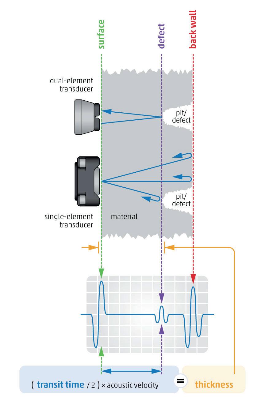
Like manual ultrasonic thickness gauging, installed ultrasonic sensors utilise the same rudiments. Ultrasonic waves are sent through the material; then using the round-trip time it takes to travel through the material and the material velocity, the distance (thickness) can be determined (Figure 1).
Equation: T = (V) x (t/2)
Where: T = Thickness, V = Material Velocity, and t = Time
Despite the similarities, the technique is fundamentally different: the transducers and instrumentation are deployed permanently or temporarily with automatic data backhaul. This addresses several of the shortcomings of existing manually deployed solutions. Some of the major advantages are as follows:
) Instrumentation and probes are deployed on the asset in a permanent or semi-permanent fashion and can be accessed remotely. The cost of access is therefore reduced over time, and operators are not deployed to the point of the inspection. Once the instrumentation is deployed, data can be remotely accessed via the Internet (IoT).
) Due to the fixed transducer position and instrumentation, operator-to-operator, probe-to-probe, and instrumentto-instrument variability are eliminated. This removes significant sources of error and allows for improved measurement resolution, precision, and accuracy which is
Figure 1. Principles of ultrasonic thickness measurement.
18 World Pipelines / COATINGS & CORROSION 2021
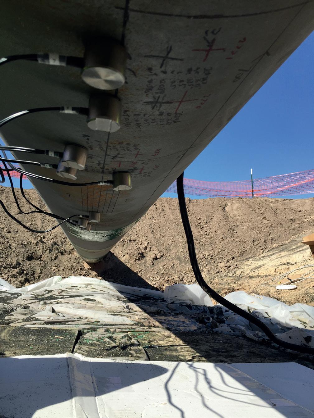
Figure 2. A newly constructed pipe with sensors installed at the low spot of the pipeline segment.
IT IS MY RESOLUTE MISSION
to overcome the most difficult obstacles, and learn from my victories and defeats. To push forward tirelessly until I succeed.
It is who I am. I am a pipeliner.
We are pipeliners too.
We share this mission and, like you, we are committed to keeping pipelines running safely and reliably. By providing end-to-end integrity solutions — from pre-in-line inspection cleaning to actionable inspection results — TDW helps you maximize the return on investment from your integrity assessments.
The world counts on you. You can count on us.
For the life of your pipeline.
tdwilliamson.com
©2021 T.D. Williamson
particularly important for corrosion-rate trending and asset management.
) Data can be collected on a more frequent basis (>1X per day) for automated systems. This allows for more accurate corrosion-rate trending through statistical data analysis.
) The system is deployed with an integrated temperature measurement device so that changes in material acoustic velocity due to temperature variation can be automatically
removed from the measurement, thus eliminating another significant source of error.
) The data is easily accessible. Wireless installed sensor systems can make use of various forms of data backhaul including the facility’s wired or wireless intranet, industrial wireless networks, satellite, or cellular networks for remote collection points, allowing real-time data/asset health availability.
Monitoring during new construction
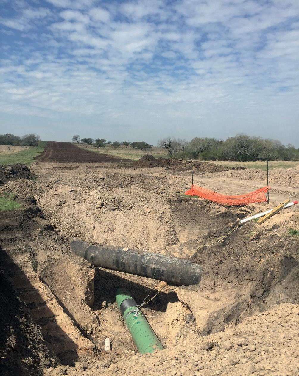
Considerable work goes into planning where a new pipeline will be laid. Factors such as environmental issues, residential limitations, topography, and many other components must be considered when ensuring pipelines’ long-term viability and safety. Many owners/operators get ahead of the curve by looking for areas they think might be prone to future corrosion attacks. Areas that have been identified as low spots or troublesome locations during pipeline plotting make for ideal locations to place sensors while it is being constructed and put into the ground (or left topside). Many of these locations are also in similar locations as the cathodic protection locations, which makes data collection more streamlined.
Figure 2 is a perfect example of a gradient change from the top of the hill in the background to the foreground where the pipeline was not only moving steadily downhill but also had to be laid below an existing line. As the pipeline continued into the foreground it went up to the top of another hill, making this location a perfect location to monitor for internal water or buildup which could potentially become corrosive in the future.
In many cases during new construction monitoring planning, a different type of sensor is used when there are no exact locations but rather a general area to be monitored. In these situations, an area monitoring sensor is recommended. Area monitoring mats have multiple elements all localised together to form a pattern or shape that collects multiple readings from the same general area.

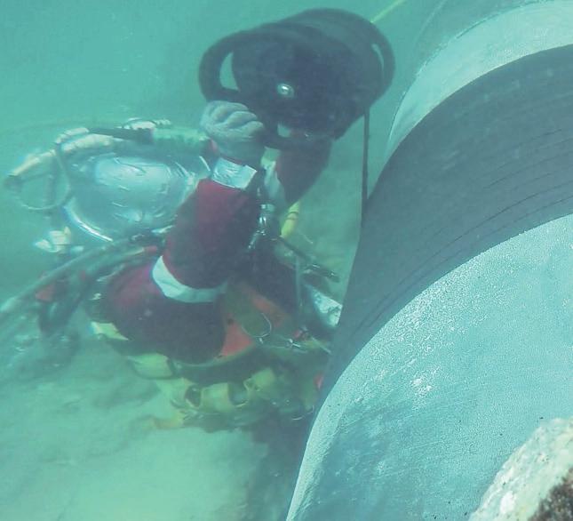
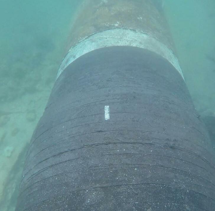
Low spot or ‘pit’ monitoring
When an anomaly is found that has surpassed maximum pit depth, a decision must be made. The anomaly must be fixed, sleeved, or repaired. If it has not reached its minimum allowed thickness, it can be monitored to gauge how ‘active’ the pit is. In many cases, corrosion is not always continuous and can be episodic in nature. To monitor the activity of the pit requires two pieces of information: identifying the pit, and extreme measurement accuracy.
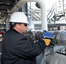
Manual readings vary greatly. When a sensor moves by 1 mm in any direction, the thickness value changes. Once the pit is found, it is marked and then a dual-element sensor is attached using a magnetic housing and epoxy (Figure 4). It is then buried with the data collection box located above ground for periodic data collection.
Data management
The ability to discern a viable and accurate corrosion rate is quite achievable. There have been many examples of how this
Figure 3. Area monitoring sensors.
20 World Pipelines / COATINGS & CORROSION 2021
Figure 4. Dual-element corrosion sensors attached using magnetic housing and epoxy.


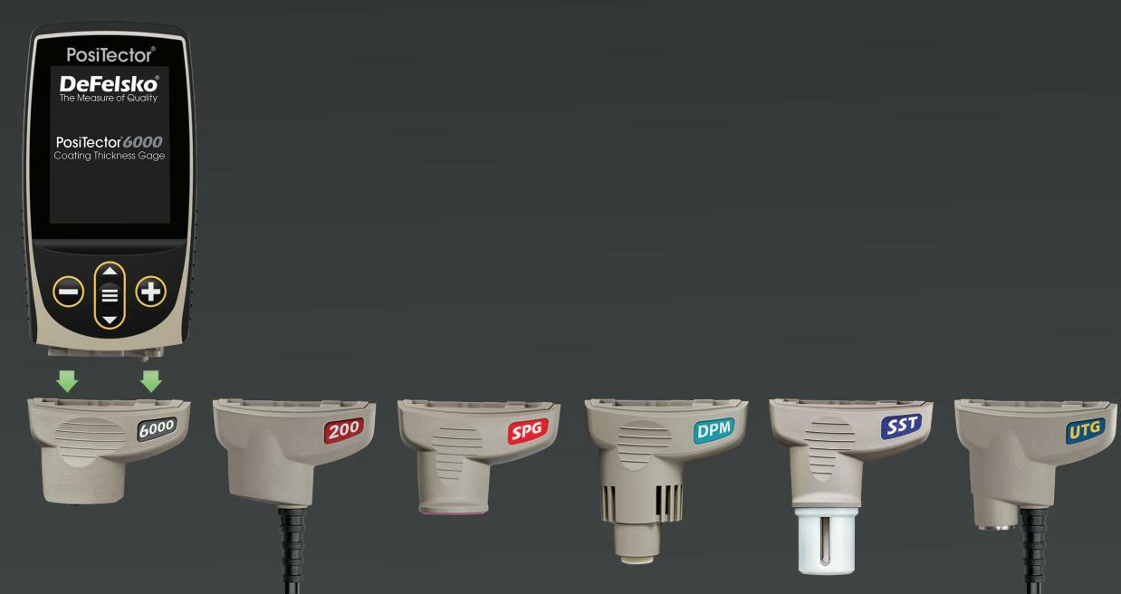
DeFelsko Corporation l Ogdensburg, New York USA Tel: +1 315 393 4450 l Email: techsale@defelsko.com B a c k w a r d s C o m p a t i b i l i t y ! Accepts ALL coa ting thickness, surface profile, environmental, soluble salt, hardness, and ultrasonic wall thickness probes manufactured since 2012 + 1 - 3 1 5 - 3 9 3 - 4 4 5 0 l w w w. d e f e l s k o . c o m Unrivaled probe interchangeability for all of your inspection needs. PosiTector ® Inspection n C o a t i n g T h i c k n e s s n E n v i r o n m e n t a l C o n d i t i o n s n U l t r a s o n i c Wa l l T h i c k n e s s n S u r fa c e P r o f i l e n H a r d n e s s n S a l t C o n t a m i n a t i o n
type of data has been able to help owners/operators not only monitor but also mitigate corrosion.
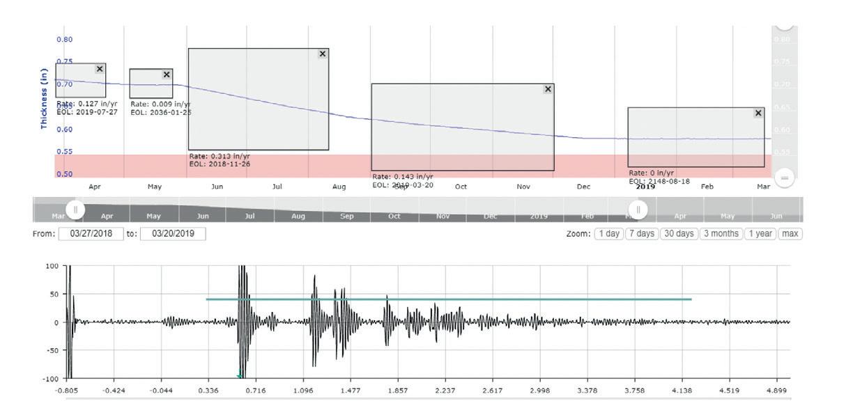
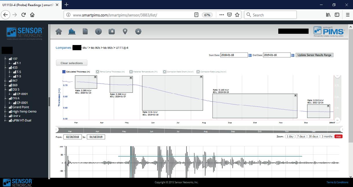
There are multiple ways to ‘slow down’ corrosion. Two of the ways are regularly scheduled cleaning pig intervals and the use of chemical inhibitors. Owners/operators know how often a cleaning is required but how much chemical inhibitor is needed to adequately protect their assets is largely unknown. In the example shown in Figures 5 and 6, an operator was taking daily readings to show the effectiveness of chemical inhibitor. As you can see, the corrosion rate significantly changed based on the amount of chemical inhibitors used at a given time.
Conclusion
Corrosion and/or erosion is a widespread and costly problem for all segments in the oil and gas chain. Currently, inline inspection, manual ultrasonics, and radiography are widely deployed to measure asset integrity for wall-thickness degradation, but all have their limitations as inspection methods. While these techniques are common and accepted, there are drawbacks in the accuracy and precision of these measurements; they only take a periodic snapshot view of asset health. Asset managers desire a more real-time view of the health of their facilities and equipment like the key performance indicator (KPI) view that they get when monitoring process variables. Additionally, the difficulty and cost of access, safety concerns, and regulatory environment changes are further driving interest in installed monitoring systems.
Figure 5. Corrosion rate trending (thickness on Y-axis, time on X-axis).
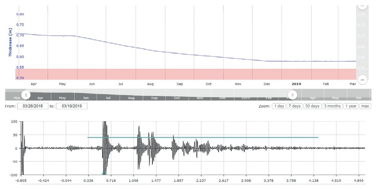
Installed ultrasonic sensors have the potential for improved asset-health monitoring as compared to current manual inspection techniques. Ultrasonic sensors are non-intrusive and permanently installed with automated or semi-automated data-collection schemes which reduce key variables, resulting in improved measurement accuracy and precision. Thus, installed ultrasonic monitoring systems can provide increased and better data, allowing the use of statistical tools to provide corrosion-rate measurements on par with other technologies, further allowing enhanced trending and feedback to process variables.
The technologies described in this paper represent commercially available options for owners/ operators to apply to their current asset integrity or inspection/monitoring programs and systems. These owners/operators are not only complying with the new PHMSA ‘Mega Rule’ and other regulations, but they are changing the way they operate to save time (resource allocation), reduce cost (monitor vs. inspect), and increase safety and efficiencies (predictive based vs. time-based maintenance) by deploying this technology.
Owners/operators and regulatory organisations are looking for different ways to work smarter. As shown, there are many ways to accomplish this objective by harnessing the power of installed buried ultrasonic corrosion monitoring sensors for midstream applications.
Bibliography
“Electrical Resistance Probes” Science Direct. https://www.sciencedirect.com/ topics/engineering/electrical-resistance-probe
H.R. Vanei. “A review on pipeline corrosion, in-line inspection (ILI), and corrosion growth rate models”. Science Direct. https://www.sciencedirect. com/science/article/pii/S0308016116302150
“Overview of In-Line Inspection”. Inspectioneering Journal. https:// inspectioneering.com/tag/ili
Regulatory Info Document 49 CFR 192, “Transportation of Hazardous Gasses by Pipeline”. https://www.govinfo.gov/app/details/CFR-2011-title49-vol3/CFR2011-title49-vol3-part192
Regulatory Info Document 49 CFR 195 “Transportation of Hazardous Liquids by Pipeline”. https://www.govinfo.gov/app/details/CFR-2011-title49-vol3/CFR2011-title49-vol3-part195
“Ultrasonic Testing”. Wikipedia. https://en.wikipedia.org/wiki/Ultrasonic_ testing
Figure 7. Example of varying corrosion rates.
Figure 6. Corrosion trending using software for time-calculated rates.
22 World Pipelines / COATINGS & CORROSION 2021
Groundsat is an innovative mapping and analysis system that includes ASTERRA EarthWorks high spatial resolution soil moisture data, that was developed following nearly half a decade of research and development.
The development of Groundsat was focused on providing a system that could inform a proactive assessment by searching for the causes of problematic ground conditions rather than monitoring the effects. Groundsat can map changes in soil moisture and provide analysis of the data alongside other datasets, which is key to understanding geotechnical risk.
EarthWorks exploits two basic principles. First: the dielectric constant is different for different materials, and through the development of patented algorithms it is possible to map the signature of water in the ground. Second: L-band synthetic aperture radar (SAR) offers advantages over other frequency bands such as X- or C-band as the wavelength of L-band is significantly greater (15 - 30 cm). This increased wavelength gives L-band radar

R. J. Pidcock, S. Blaney, B. Bilsbrough and E. Taylor, RSK Group, UK and E. Segal, Y. Lorig, ASTERRA, Israel, offer a desk-study-based assessment for pipeline design, construction and operation phases using ASTERRA
EarthWorks soil moisture data and Groundsat mapping and analysis.
23
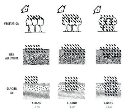
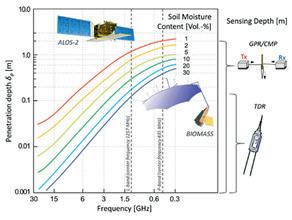
Figure 1. SAR penetration as a factor of the wavelength (λ) and penetrated medium (Aukema, Wilson, & Irwin, 2019).
the ability to penetrate vegetation and into the ground, a significant difference when compared with Interferometric SAR (InSAR) surface deformation monitoring.
Long-wave SAR has penetration capabilities depending on its frequency, land coverage, soil type, soil wetness (Koyama et al., 2017; Aukema, Wilson and Irwin, 2019; Nolan and Fatland, 2003) and incidence angle. L-band SAR has proven its penetration capabilities, starting at the Shuttle Imaging Radar (SIR-A) in 1982 that was flown in the Columbia space shuttle and uncovered ancient riverbeds with its penetration (McCauley et al., 1982).
L-band backscatter data providing high correlation with gravimetric and volumetric measurements on field soil samples have been demonstrated in a variety of research (Sonobe et al., 2008; Ponganan et al., 2016; El Hajj et al., 2019; Zribi et al., 2019).
EarthWorks data have also provided high correlations and repeatability when correlated to field soil samples, both when tested in the laboratory for gravimetric water content (GWC) and with in-situ soil moisture probes measuring volumetric water content (VWC). Field data were collected within a two hour window of the satellite image acquisition.
The relationship between microwaves and soil moisture content has been studied over several decades. The use of satellite microwave remote sensing technologies for quantitative soil moisture mapping was introduced in the 1980s with SAR technology.
This method was applied and proven accurately on the upper soil thin layer (5 - 10 cm depth) (Behari, 2005). The main limitation was the spatial resolution, which was too coarse. Other limitations were soil texture, surface roughness and vegetation coverage. The use of novel full (quad) polarimetric SAR imagery and L-band, which is known for its capabilities for soil moisture content detection and penetrates both the vegetation coverage and the topsoil layer, plays a major role in the improved accuracy of the results.
The ability to estimate soil electrical conductivity using L-band SAR and specifically the ALOS-2 PALSAR satellite has been proven using actual field measurements (Phonphan, 2017; GUO, et al., 2013).
Data acquisition for a changing world
The use of satellite-based data, such as EarthWorks soil moisture mapping, is an innovative technique that has the power to change how we operate in difficult times, to the benefit of all stakeholders. Groundsat helps address the significant challenges that infrastructure owners and operators face with the increasing impact of climate
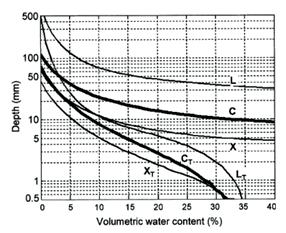
 Figures 2 and 3. The penetration depth as a factor of the transmitted frequency and the soil moisture content (left figure from Nolan and Fatland, 2003, right figure from Koyama et al., 2017).
24 World Pipelines / COATINGS & CORROSION 2021
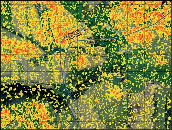
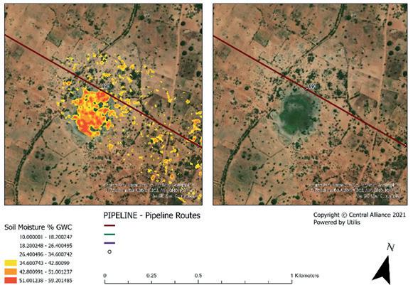
Figure 4. Example of EarthWorks soil moisture mapping data with relative soil moisture values shown above 30% GWC (yellow into red), overlaid onto an optical satellite image within Groundsat with pipelines shown in dark blue (ASTERRA and Central Alliance).


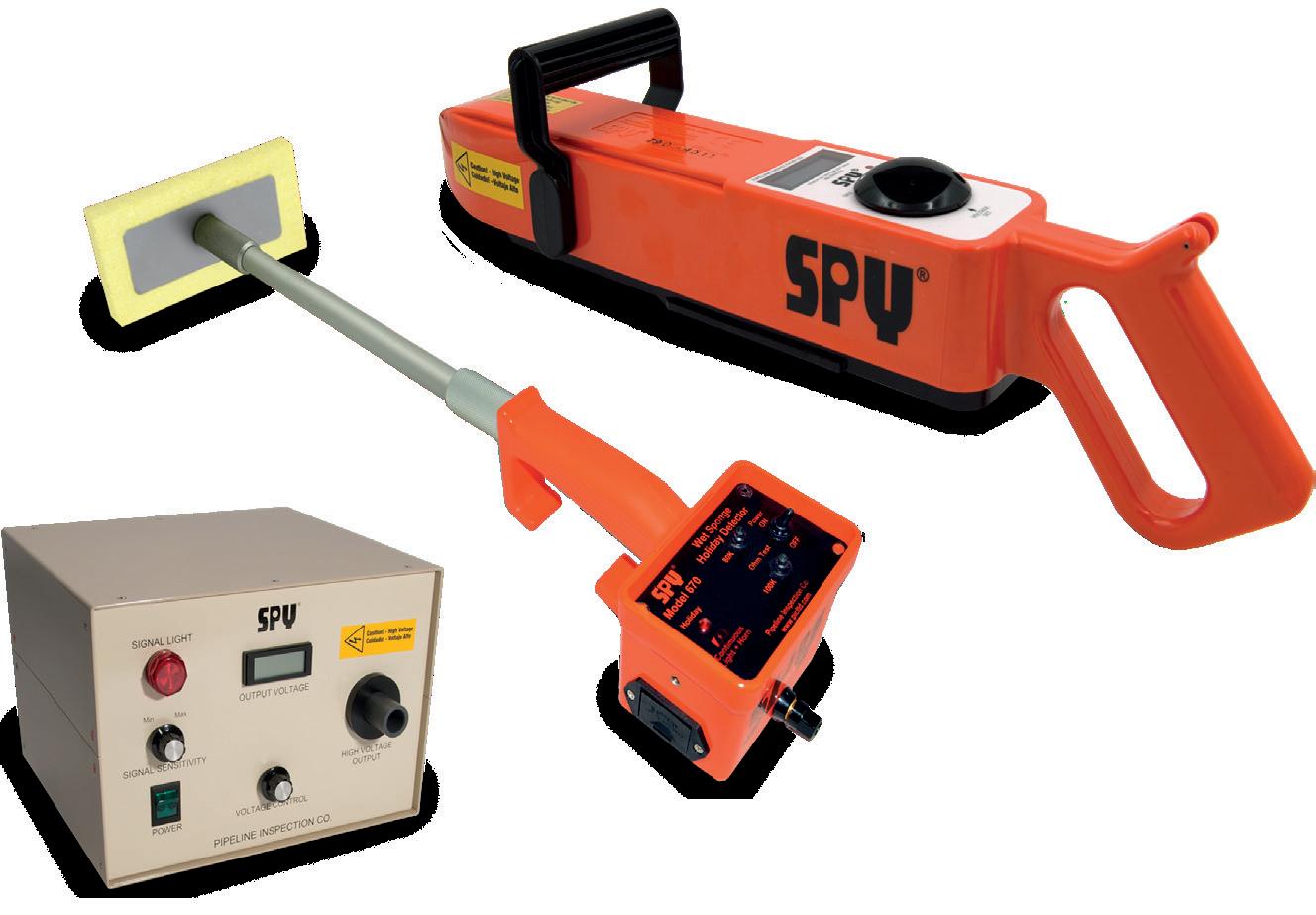
Untitled-5 1 SPYINSPECT.COM • (713) 681-5837 • Accurate • Tough • reliable THE LEADING BRAND OF HOLIDAY DETECTION EQUIPMENT SINCE 1953
change, in terms of both acquiring pre-construction data for design and for assessing asset resilience. The technique utilises existing earth observation satellites and requires no access to the site, no travel and no exposure to risk; it covers large areas and therefore reduces costs and carbon footprints for both data acquisition companies and asset owners, while also providing a safer means of acquiring data through all phases of design, construction and operation.
Pipeline analysis
Pipelines are a key part of critical global infrastructure and offer a mode of transportation for fluids with significant economic benefits over other methods of transportation.
“Pipeline damage statistics from Canada, Europe and the United States indicate that about one-eighth of all pipeline damage incidents over the last 30 years have been due to geotechnical hazards. It has been noted that pipeline failures induced due to ground movements would typically lead to damage costs more than double those arising from other hazards” (Dharma Wijewickreme).
Understanding soil moisture and ground conditions is essential in both the design and construction and operation phases of buried pipelines. The consequences of pipeline failure can be expensive from both economic and environmental perspectives. For applications in pipeline route assessment, soil moisture hazard analysis and preconstruction spoil management, Groundsat can provide valuable intelligence to constructors and operators of large diameter pipelines, over long distances.
Design, pre-construction and construction phases
The interaction between buried pipes and the surrounding soil is complex. Buried pipelines and foundations for overground pipelines interact with the soil surrounding them and are subject to the additional stresses transmitted by the movement of the ground. These can be exacerbated with increased shrink-swell potential of the soil in addition to more extreme circumstances, such as the translation of the soil in the event of shallow landslides on slopes and liquefaction during earthquakes.
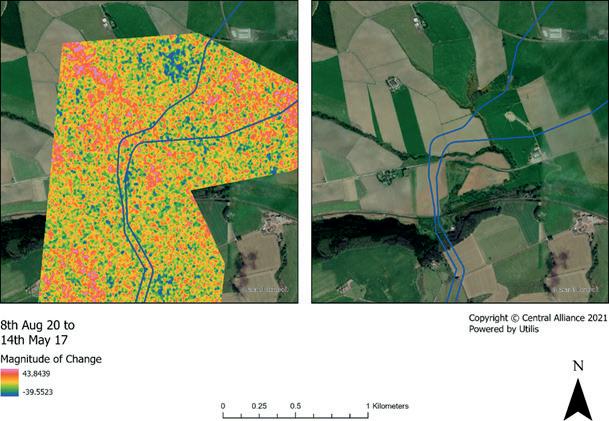
Figure 5. Example of EarthWorks magnitude of change soil moisture mapping data, showing the change between two images at different times of the year, highlighting where seasonal variation is at its highest. The optical satellite image on the right shows land cover. Correlations can often be observed within Groundsat, but land cover type, including crop type and stage of growth, along with geology can be seen to influence soil moisture and change over time. Pipelines are shown in dark blue (ASTERRA and Central Alliance).
Using Groundsat, it is possible to identify areas of concern where high soil moisture and increased pipe stresses coincide, such as at the position of a change of pipeline direction or a change of longitudinal gradient. Furthermore, using EarthWorks high-resolution soil moisture data combined with spatial data, it is possible to inform the placement of right-of-way drainage or the requirement for revetments where areas of high soil moisture exist that are deemed likely to influence soil stability.
Soft and boggy ground can pose operational problems during construction and understanding the soil moisture during the route selection stage is critical for planning, budgeting for safe construction and to meet required construction programmes. Figure 4 provides an example of soil moisture data overlaid onto an optical satellite image showing land cover.
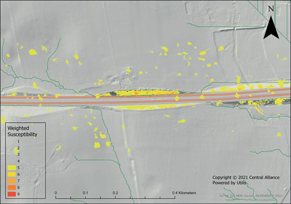
Figure 6. Example Groundsat soil moisture-based weighted susceptibility mapping, incorporating soil moisture values and slope angle (from lidar DEM), each scaled 1–10 and weighted 50–50, highlighting where high soil moisture and slope angle combine (ASTERRA and Central Alliance).
During route selection, geohazards are a key aspect to consider. Pipelines must be designed to accommodate the additional load from the surrounding soil. Groundwater and pore pressures need to be considered in design, along with the potential for change in groundwater regimes and pressures. Additionally, buoyancy forces due to groundwater need to be carefully considered. Where hydrostatic uplift from groundwater exceeds the downward forces of the pipe, its contents and soil overburden, this can lead to critical situations, exacerbated when the pipe is empty or filled with air or gas.
Figure 5 provides an example of Groundsat-processed data from a similar area to Figure 4. At this location,
26 World Pipelines / COATINGS & CORROSION 2021
significant seasonal change in soil moisture values between wet and dry seasons can be observed. Understanding this change is critical for both pipeline design, route selection and monitoring during operation, particularly in terms of asset resilience to climate change. Figure 5 highlights the magnitude of change between soil moisture values calculated from two separate L-band SAR images.
Soil moisture mapping provides information that can help establish these risks, along with other geotechnical considerations and geohazards such as landslides, earthquake-induced liquefaction and ground movements.
When considering landslide susceptibility, Groundsat analysis of soil moisture data in the geographic information system (GIS) enables other datasets such as lidar-based digital elevation models (DEM) to be incorporated. Combining EarthWorks soil moisture data and the slope angle enables susceptibility mapping to be carried out, highlighting where high soil moisture and a high slope angle combine. Soil moisture mapping data provide a further source of information to aid in the identification of high-risk areas that together with more conventional survey and investigation methods enables improvements in prioritising targeted intervention. Furthermore, the Groundsat system provides the designer with another layer of information that would be difficult and costly to obtain using other, more terrestrial, techniques.
Temporary placement of spoil material removed from trenching activities can present additional hazards when placed on saturated ground and subsequently becoming saturated itself, as is highlighted by recent failures. Soil moisture mapping data combined with GIS and hydrological analysis can be used to inform the best location for spoil to avoid areas of high soil moisture and slopes combining, thus reducing the risk of geotechnical failure of the spoil deposits. This assessment can be valuable both during and post-construction where permanent excess spoil remains in place.
Wide area coverage also enables the assessment of soil moisture and run-off from watershed areas or catchments that directly affect the pipeline corridor, enabling
management of run-off, an essential requirement with a changing climate and more severe weather events.

Operation phase
Pipeline corrosion in soil is a complex phenomenon comprising several mechanisms. Alongside parameters such as soil acidity, soluble salt concentration and electrical resistivity, soil humidity and thus soil moisture plays a significant role in corrosion rates in soils, as demonstrated by Murray and Moran (1989). The study reveals that pipeline steel corrosion could occur at a rate of three orders of magnitude higher in soils in near-saturated
Put Down Your Work Gloves.
(We’ve got this.)
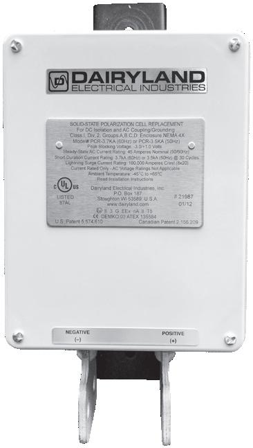
Maintaining a pipeline is no easy task. With so many things to worry about, you need products you can depend on. Always. Our solid-state decouplers help improve your cathodic protection system’s performance and stand up to AC faults and lightning strikes, in all sorts of conditions. We make them rugged so that you can trust them to perform. Always.
Applications
• AC
Grounding
Include:
Voltage Mitigation • Insulated Joint Protection • Decoupling Equipment
Systems • Gradient Control Mat Isolation Learn more about our Always Rugged Promise: Dairyland.com/AlwaysRugged
Figure 7. Example EarthWorks soil moisture mapping data with relative soil moisture values shown above 34.6% GWC (yellow into red), overlaid onto an optical satellite image showing land cover (ASTERRA).
condition than those located in near-dry conditions. From this study, the detection of high soil moisture areas throughout the proposed route of the pipeline is useful to aid the preparation of a sampling regime and a better focused ground investigation campaign, where required.
Pipelines used for the transportation of waxy, highly viscous oil need to be heated to reduce the viscosity of the oil sufficiently for it to flow freely through the pipeline. Moisture around an underground pipeline sometimes experiences heating from the pipe, causing evaporation. It has been shown that in areas of increased saturation, this results in a decrease of compressive forces, which is considered a benefit to the stability of a pipeline, according to Zhu et al. (2019). Using Groundsat to identify areas of saturation can help with route planning. Unexpected changes to moisture content may indicate areas of increased heating. Early identification of these areas could enable inspections of specific sections where insulating material may be failing or other faults are developing. Figure 7 provides an example of soil moisture mapping data for potential use in both assessing corrosion and heat-loss susceptibility.
Conclusion
Groundsat mapping and analysis system, incorporating ASTERRA’s EarthWorks soil moisture data, is a proactive data acquisition technology that searches for the causes of problematic ground conditions rather than monitoring the effects.
Understanding soil moisture and ground conditions is essential in both the design and construction and operation phases of buried pipelines. High resolution soil moisture mapping forms an important dataset during
the design, pre-construction, construction, and operation phases of a pipeline lifecycle to assess geotechnical risk. Analysing the data alongside other datasets extracts further value. The combination of soil moisture data and an accurate digital elevation model enables a comprehensive desk-based GIS assessment to be undertaken, which may highlight areas where soil is sensitive to increasing moisture. Based on this susceptibility analysis, remedial solutions, such as drainage, can be used to address issues related to increased soil moisture or in the case of pre-construction, used to inform route design to enable improved spoil management during construction.
EarthWorks combined with GIS analysis can provide insights into the risk of landslides and geohazards on natural ground surrounding a pipeline. Wide area coverage enables the assessment of soil moisture and run-off from watershed areas or catchments that directly affect the pipeline corridor, enabling the management of run-off, an essential requirement with a changing climate and more severe weather events.
Bibliography
AUKEMA, J., WILSON, S. and IRWIN, D. (2019). The Synthetic Aperture Radar (SAR) Handbook: Comprehensive Methodologies for Forest Monitoring and Biomass Estima tion. Huntsville, AL: SERVIR Global Science Coordination Office.
BEHARI, J. (2005). Microwave Dielectric Behaviour of Wet Soils. New Delhi: Springer. GUO, Y., SHI, Z., ZHOU, L.-q., JIN, X., TIAN, Y.-f. and TENG, H.-f. (2013). Integrating Remote Sensing and Proximal Sensors for the Detection of Soil Moisture and Salinity Variability in Coastal Areas. Journal of Integrative Agriculture, pp. 723 - 731.
KOYAMA, C. N., LIU, H., TAKAHASHI, K., SHIMADA, M., WATANABE, M., KHUUT, T. and SATO, M. (2017). In-Situ Measurement of Soil Permittivity at Various Depths for the Calibration and Validation of Low-Frequency SAR Soil Moisture Models by Using GPR. Remote Sensing, p. 580.
MCCAULEY, J. F., SCHABER, G. G., BREED, C. S., GROLIER, M. J., HAYNES, C. V., ISSAWI, B., … BLOM, R. (1982). Subsurface Valleys and Geoarcheology of the Eastern Sahara Revealed by Shuttle Radar. Science.
MURRAY, J.N., MORAN, P.J. (1989). Influence of moisture on corrosion of pipeline steel in soils using in situ impedance spectroscopy. Corrosion Science. Volume 45, pp. 3443.
NOLAN, M. and FATLAND, D. R. (2003). Penetration depth as a DInSAR observable and proxy for soil moisture. IEEE Trans. Geoscience and Remote Sensing, pp. 532 - 537.
PHONPHAN, W. (2017). Using Regression Models to Predict Electrical Conductivity of Soil Through ALOS PALSAR Satellite. Journal of Engineering and Applied Sciences, 12, pp. 7276 - 7279.
PONGANAN, N., PRASEARTKUL, P., PIPATSITEE, P., TAOTA, K., KONGPUGDEE, S., SAKUL LEERUNGROJ, K. and EIUMNOH, A. (2016). The determination of soil water content in various depth levels in cassava fields using ALOS-2 PALSAR Imageries. Asian Association on Remote Sensing 2016 Conference proceedings.
SWEENEY, M., GASCA, A.H., GARCIA-LOPEZ, M. and PALMER, A.C. (2005). Pipelines and landslides in rugged terrain: a database, historic risks and pipeline vulnerability. Terrain and Geohazard Challenges Facing Onshore Oil and Gas Pipelines. Thomas Telford, London, pp. 641 - 660.
SONOBE, R., TANI, H., WANG, X., FUKUDA, M. (2008). Estimation of Soil Moisture for Bare Soil Fields Using ALOS/PALSAR HH Polarisation Data. Agricultural Information Research 17(4).
WIJEWICKREME, D. Role of Geotechnical Engineering in assuring the Integrity of Buried Pipeline Systems. University of British Columbia.
ZHU, B., YE, Z., WANG, L., KONG, D., XU, W., KOLDITZ, O., NAGEL, T. and CHEN, Y. (2020). Hydro-mechanical behaviour of unsaturated soil surrounding a heated pipeline consider ing moisture evaporation and condensation. Computers and Geotechnics, Volume 119.
The myriad of complexities posed by COVID-19 made it harder than ever for operators to stick to the planned inspection programmes of their piping and pressure systems. But, while the pandemic restrictions certainly exacerbated the challenge, it was hardly a new phenomenon.
The average safety critical backlog of the oil and gas industry as a whole rose by 44% between 4Q18 and 4Q19, according to OGUK’s Health, Safety and Environment Report 2020. Most of the increase, says the report, stemmed from deferrals. It throws into sharp relief the quandary faced by asset and integrity managers as they try to articulate where their piping and pressure inspection priorities – and deferral options – lie.
Resource and schedule constraints are of course the main root causes behind deferrals, but issues can come into play if regulatory approval is the only or main thrust of the tactical response.

In tightly regulated locations like the United Kingdom Continental Shelf (UKCS), regulatory bodies maintain a watchful eye over integrity management plans and most will require clear and robust technical justifications for the rescheduling of safety critical inspections. However, the narrow regulatory view for deferrals does not appreciate all the opportunities in which deferral plans can be better optimised. This being so, regulatory approval should be considered as a benefit of a wellconsidered deferral plan, but there will always be a higher bar to achieve.
There are also, of course, in-house imperatives driven by safety, optimisation and efficiency, which often gives way to a difficult balancing act. In pursuit of efficiency, operators will sometimes defer a non-critical inspection without considering the implications, for example greater
Christopher Blake, Head of New Business for IMRANDD, details how operators can make deferral decisions by optimising the use of their data.
29
maintenance costs down the line. In other cases, inspections are performed that could reasonably have been pushed back – taking away time from inspections that would have caught failures in the making. Some of these decisions were undoubtedly taken because the integrity team was unable to leverage a dataset or lacked confidence in the data available.
Trust in data?
This highlights a wider conversation around the perceived lack of trust in some areas of asset integrity around the use of data – and it also poses the question of whether we can and should move on from our conventional piping and pressure system inspection practices. More strategic asset management, using the available resources to hand – not least, easily extracted, robust data – could take us in a new, even safer and more costeffective direction. It’s a strategic issue we’re very focused on at IMRANDD.
Deferral justifications can take many forms; they may involve time-consuming reviews of past data, alongside intermediate or non-intrusive inspections to satisfy assumptions that deferral is acceptable. Or operators might take the condition of some items in a suite of equipment – a set of valves, for example – as representative of all of them and push inspections of some valves back a year, confident in the assertion that degradation levels are lower than had been anticipated.
But, rather than extrapolating the available information, what if the operator had actual data on all of its valves within its piping and pressure systems and harnessed that knowledge to make fully informed deferral decisions? It’s generally accepted that, as an industry, we’re good at collecting asset data – but we come up short in harnessing it and then deploying it to material advantage.
Data-based deferrals
There are three key outputs when you build a data model based on the comprehensive digital knowledge of a facility’s piping and pressure systems. Firstly, you gain a better and clearer understanding of the likelihood of failure under certain conditions and over a set period of time. With knowledge you can monitor for changes to those conditions and are empowered to seek the resources to inspect within the appropriate timescales.
Secondly, it provides the ability to understand where you may be over-inspecting. From here, you can then target inspection resources with much greater efficiency while also underpinning your deferral justifications to regulators.
Finally, a robust model can also expose potential gaps in the availability of quality asset data, and these gaps can then be closed through targeted inspection, reviewing wider industry knowledge or by supplementing your model with additional data.
Our AIDA data analytics tool, which equips operators to better understand both legacy data and the ever-growing levels of new data generated by technological advances, provides these outputs and more. The software solution mitigates risks because decisions are based on solid, reliable data; on hard evidence. By forming a data model of the
degradation of a facility’s piping and pressure systems, we’re moving away from the principles of inspecting to either find a defect or confirm its absence. Instead, we’re curating the data model so it’s more accurate and more representative of the overall condition of the equipment and/or asset: a tool, a resource, that’s constantly updated and driving decisions by looking at the performance of an asset in a more holistic way. Using this approach, the value from inspection shifts from only being gained when a defect is found, to all outcomes that can improve the data model.
Smoothing the road ahead
If you’re simply inspecting in the here and now for individual areas of corrosion or other prospective failures, you’re not necessarily understanding the overall condition of the piece of equipment, associated systems and – critically – what issues may lie around the corner. It’s perhaps comparable to driving a car along a street: instead of constantly looking down for potholes or other imminent accident hazards, it’s safer to be looking up at the road ahead. You’re seeing the bigger picture and anticipating, in the longer term, where the pitfalls might lie. Our optimisation tool REFLEX also leans into the data to support the execution of plans as efficiently as possible, and is based on assessing available resource (staff, bed space) against schedules, time and cost. It helps operators manage both the peaks of activity – where they’re having to make decisions based on priorities – and the troughs, where there are opportunities to make best use of resources and get more work done. The two solutions are in many respects closely intertwined in terms of aligning safe deferral decisions and reshaped inspection programmes. Indeed, REFLEX can be strategically key in first optimising asset activities and therefore informing any deferral process.
Conclusion
Assuring the continued integrity of piping and pressure systems is a critical safety issue which is felt particularly acutely by operators in the UKCS, where many producing assets are operating way beyond their original 25 - 30 year design life. Asset owners find themselves under constant pressure to extend the life of this critical infrastructure and operate safely while continuing to meet ongoing energy demands.
As operators contend with greater numbers of ageing assets, managing safety critical backlogs, as well as justifying deferral plans, will be at the forefront of many asset and integrity managers’ minds. By leveraging existing piping and pressure system data using tools such as IMRANDD’s AIDA and REFLEX, operators become better equipped to pursue a strategy that makes best use of resources, at the right time, to deliver on their long-term safety, operational and commercial objectives.
Asset owners already have all the data they need to put the solution in place, it’s simply a matter of using data in a smarter and more efficient way. With many operators struggling under the burden of managing their piping and pressure system maintenance backlog, the approach provided by IMRANDD has the potential to create a real step-change in industry, bringing a new era in how data is used to maintain operability, profitability and safety.
30 World Pipelines / COATINGS & CORROSION 2021
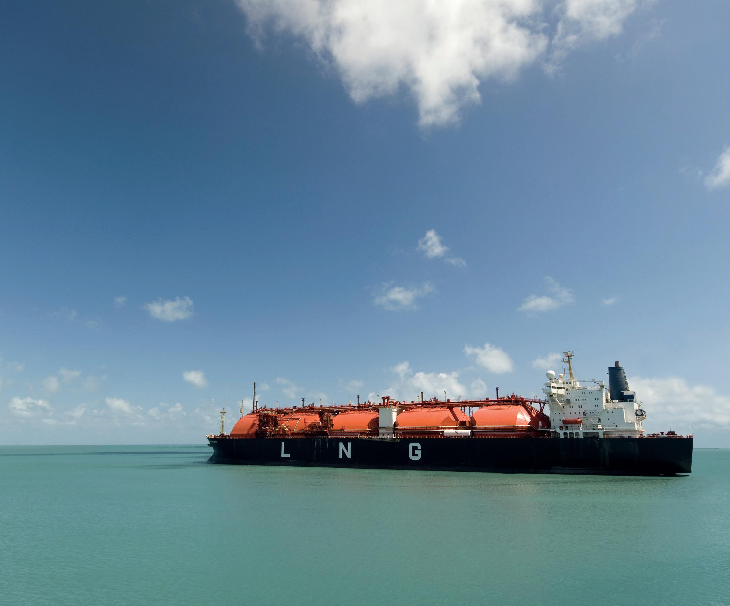


LNG Industry magazine
your
value
Register for
free subscription at: www.lngindustry.com Global coverage of the entire LNG
chain

32
Rod Lee, Pipetel Technologies Inc. (an Intero company) presents an overview of key milestones in Pipetel’s journey of providing certainty and safety to challenging and unpiggable pipelines around the world.
Although Pipetel (which recently became an Intero Company) began operations in Canada and the US in 2010, the development of EXPLORER inline inspection robots for transmission natural gas pipelines started in 2003 with InvoDane Engineering under the leadership of NYSEARCH. Part of the Northeast Gas Association, NYSEARCH is a member-funded organisation that focuses on technology research for the benefit of the natural gas industry and its customers in the US. This article presents an overview of key milestones in Pipetel’s journey of providing certainty and safety to challenging and unpiggable pipes from the company’s beginnings in North America to its current expansion worldwide.
In 2007, after years of painstaking development, we saw the first deployment of the original EXPLORER 6/8, for inspection of 6 and 8 in. diameter pipes, in a live natural gas pipe for testing. Further refinement over the next few years allowed us to finesse the technology and commercialise the robot into a service offering that solves a major problem in the oil and gas industry –the inline inspection of unpiggable pipes.
Pipeline integrity leaders and professionals with challenging and unpiggable pipeline assets need reliable and accurate data to determine the state of their assets as part of a well-rounded integrity management programme. In order to reduce risk and exposure to incidents, inline inspection provides the most comprehensive data to develop a safety programme that meets or exceeds mandated standards and significantly reduces the probability of incidents. However, traditional inline inspection methods may not be suitable for all unpiggable pipes.
Unpiggable inspections

In 2010, Pipetel officially formed, with its sole mission to provide certainty and reduce risk in unpiggable pipes. In the next year, we completed our first inspection of an 8 in. diameter pipe, embarking on the journey to make unpiggable pipes safer. EXPLORER 6/8 at the time had a camera for visual inspection and a remote field eddy current sensor for detecting corrosion. That year, we inspected pipes for a Canadian operator and a US operator as well as successfully completed our first ever, robotic inline inspection of otherwise unpiggable pipes that were in service without shutting down the natural gas pipes. EXPLORER 6/8 entered and exited through an industry-standard hot tap fitting.
In 2012, we added the EXPLORER ILI 10/14 to our fleet, to inspect pipes in the diameters of 10, 12, and 14 in. This was the first EXPLORER ILI robot featuring tri-axial sensing and a high-resolution Magnetic Flux Leakage (MFL) sensor. The following year, due to popular demand of our first robotic MFL service, we released the EXPLORER ILI 20/26 to provide a much-needed service to keep larger diameter pipes of 20, 22, 24, and 26 in. safer.
By developing self-propelled, robotic inline inspection tools, Pipetel became an industry leader in the inspection of unpiggable pipes by providing the best visibility of imminent threats. EXPLORER ILI robots capture high quality, accuracy, and quantity of data for industry-leading operators to achieve certainty and reduce risk of incidents in challenging to inspect pipes. By reducing imminent and future risks with comprehensive integrity data, operators will experience a reduction in operational,
33
liability, and property damage costs. They will also see better protection of their reputation as a safe and reliable operator. Additional benefits for operators include enhanced uptime and the potential to increase product throughput which can result in increased revenue while also maintaining high safety standards.
Inspecting longer pipelines
One of the most common demands from operators we began to receive, after having a fleet of three EXPLORER robotic tools, was to extend our service to include the ability to inspect longer pipes. In 2014, Pipetel responded by introducing a proprietary inline charging (ILC) process and technology. The ILC technology recharges EXPLORER inside the pipe to extend the range of inspection and expanded our service offering to no longer
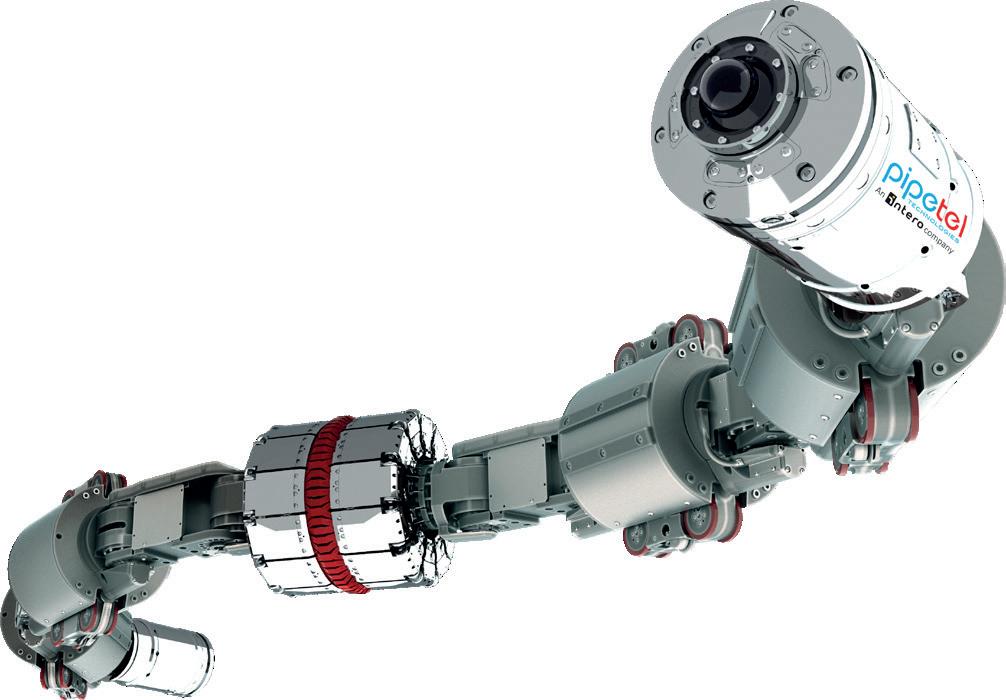
be limited by the inspection distance capable with a single battery charge. This technology is also able to be used with no interruption to gas service. Since the introduction of our ILC technology and process, Pipetel’s longest continuous inspection conducted is 4 km.
In that same year, we introduced our Laser Deformation Sensor (LDS) onto each EXPLORER ILI to add the collection of deformation data by all EXPLORER robots. It was at this time that EXPLORER robots became a combination tool with visual, MFL, and laser deformation sensors. This additional data has proven to provide vital information to operators, revealing common threats due to third party damages to unpiggable pipes. Collecting this multipoint data better reveals imminent threats and thus keeps unpiggable pipes safer.
Terminals and facilities
In 2015, we began inspecting liquid pipes in terminals and facilities, extending the benefits of robotic inline inspections to not only natural gas pipeline operators but liquid pipe operators as well. We also continued to expand our inspection capabilities to include 16 and 18 in. diameter pipes by introducing EXPLORER ILI 16/18. The next additions to our fleet included the EXPLORER ILI 30/36 to inspect pipes of 30, 32, 34, and 36 in. in diameter and the development of a new and improved EXPLORER ILI 8 to replace the original EXPLORER 6/8 with an inline inspection robot that collects multipoint data. Finally, we completed our lineup of multipoint data collecting robotic tools in 2020 by adding the smallest robot in our fleet – EXPLORER ILI 6. This expansion to our fleet allows us to inspect pipes from 6 - 36 in. in diameter.
Focusing on pipeline safety
Over the years, our teams have worked tirelessly to improve pipe safety across the US and Canada. The longest project, with multiple sections of inspection, that we have inspected was 14 km. Relentlessly and strategically focused on pipeline safety of difficult-to-inspect pipes, we lead the industry in the ability to navigate unpiggable pipes. Our team conducts inspections safely and accurately to collect the highest quality and breadth of data possible so that pipeline operators can make the most informed decisions about their assets.
We always encourage our team to be innovative, customerfocused, responsive, flexible, and have integrity to provide operators with the best experience and assurance that they will receive the most complete information to utilise as part of their asset integrity programmes.
In January 2021, we extended our mission of keeping unpiggable pipes safer all over the world by merging with Intero Integrity Services. This strategic alignment means that the benefits of a multipoint MFL, LDS, and visual inline inspection are no longer limited to North America, but are now available worldwide. Both companies have the same focus on difficultto-inspect pipes, high service levels, state-of-the-art technology including robotics MFL as well as free-swimming Ultrasonic Transducer (UT) tools to provide a plethora of integrity
solutions
pipe
us
company An CANADA 44 Metropolitan Road, Toronto, ON M1R 2T6 + U.S.A. 300 International Drive, Suite 100, Williamsville, NY 14221 Main: 416-510-8588 pipetelone.com Toll free: 1 855-747-3835 2007 Explorer 6/8 with video and eddy sensor tested in live gas pipes 2010 Pipetel formed to provide certainty and reduce risk in unpiggable pipes 2011 1st inspection of 8" diameter pipe in service, inspected pipes for 1 US operator and 1 Canadian operator 2012 Explorer 10/14 first deployed for inspecting 10"-14" pipes with tri-axial MFL 2013 Explorer 20/26 deployed to expand MFL inspections to 20"-26" pipes 2014 In-line Charging (ILC) technology developed to extend inspection range beyond a single battery charge 2014 Laser Deformation Sensor (LDS) added onto Explorer MFL robots, giving them the ability to collect MFL, LDS, and video data 2015 Began inspecting liquid pipes in terminals and facilities 2015 Introduced Explorer 16/18, Explorer 30/36, and new MFL Explorer 8 2020 Introduced new Explorer 6 2021 Extended mission of keeping unpiggable pipes safer worldwide by merging with Intero Integrity Services
self-propelled, remotely
with multiple data
sensors.
34 World Pipelines / COATINGS & CORROSION 2021
and options for all pipeline operators. As
assets age, all of
at Intero and Pipetel strive to continuously help operators improve the safety of pipelines globally.
Figure 1. Tetherless,
controlled EXPLORER ILI robot
collecting
Figure 2. Historical timeline of Pipetel’s technology.
VERIFYING INTEGRITY: A how to
In petrochemical and refining facilities, material verification of pipes, components, and other assets is critical for safety. The wrong material can corrode at an accelerated or unpredictable rate, increasing the risk of unexpected failures and catastrophic incidents.
Handheld X-ray fluorescence (XRF) analysis plays an important role in material verification for pipeline integrity. This article will discuss how to set up a material verification programme that integrates handheld XRF and other testing methods.
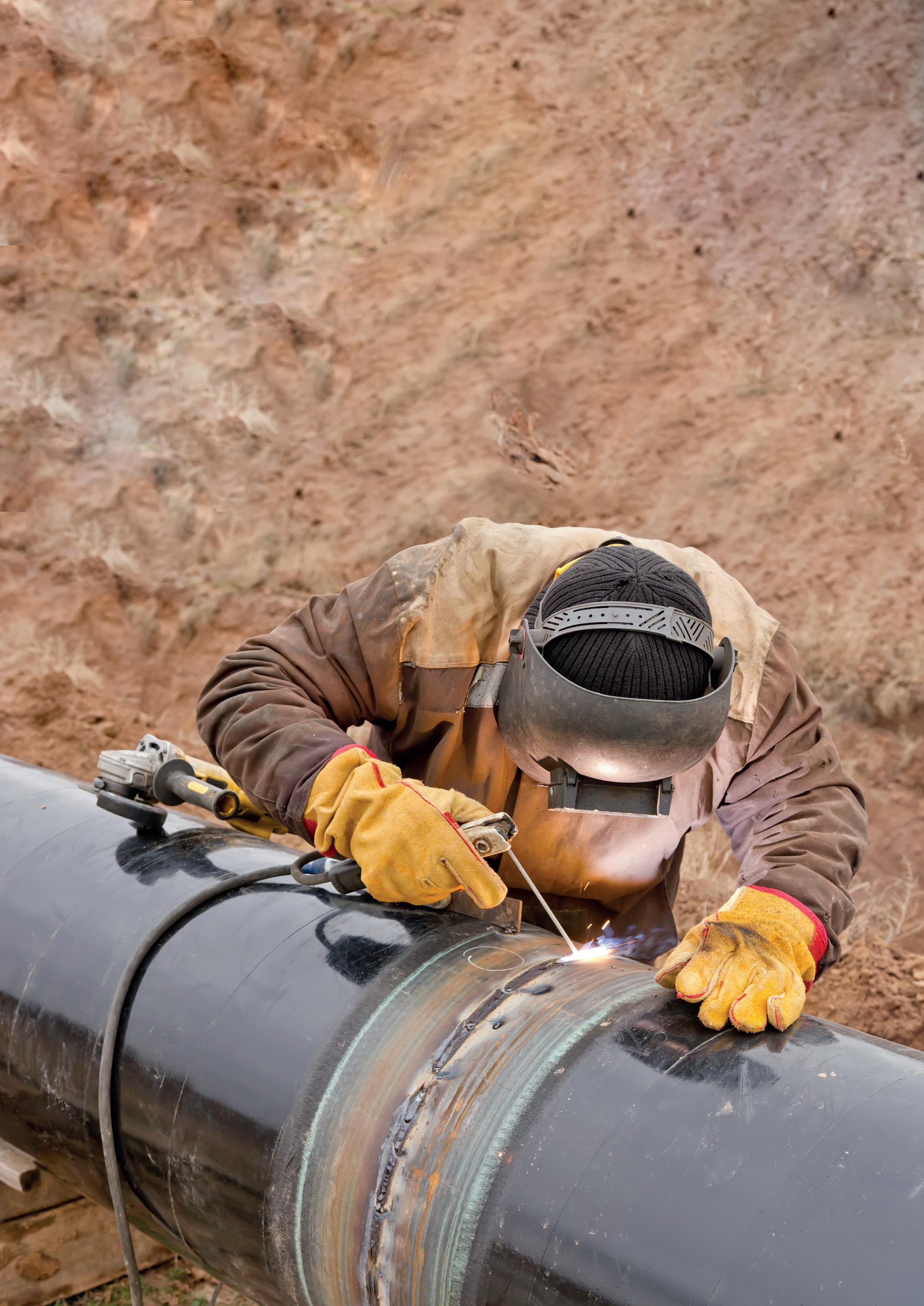 Peter Faulkner, Director of Market Development, Olympus Scientific Solutions Americas, USA, discusses the role of handheld XRF in material verification for pipeline integrity.
35
The importance of a material verification programme for piping systems
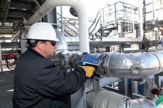
Material mix-ups can occur at the component manufacturer, on delivery, during stocking or restocking, or during installation. While proper labelling and material test reports (MTRs) can help prevent material mix-ups, these costly errors continue to occur. Major incidents at oil and gas facilities are frequently attributed to accelerated corrosion due to incorrect material installations.
Throughout the world, various authorities such as the Pipeline and Hazardous Materials Safety Administration (PHMSA) in the US, the European Gas Pipeline Incident Data Group in Europe, and the National Energy Board (NEB) and Energy Resources Conservation Board (ERCB) in Canada have shown that corrosion and material failure are responsible for significant failures in oil and gas pipelines.
Implementing a material verification programme, or MVP, in petrochemical and refining facilities can help minimise the possibility of unexpected failures from material mix-ups.
Material verification programme recommended practices
A material verification programme is a quality management process to assess alloy materials throughout the life of components from raw materials to final installation at the refinery. This programme helps ensure that every part installed at the refinery meets the alloy specifications required to stand up to pressure, heat, corrosion, and other environmental demands. Parts tested include individual pipes and flanges in a manufacturing plant to fully assembled systems such as piping, pumps, vessels, and reactors.
A material verification programme should also consider the maintenance and inspection of existing assets. During routine service, engineers and materials scientists carefully consider the final operating conditions of assets while anticipating certain deviations from normal operations. They consider the physical and chemical expectations of any components in the process. This includes variations in operating conditions from the original specifications. For
instance, regional variations of crude oil sulfur content may occur with the increased demand for higher level sour crude oils.
Both American Petroleum Institute (API) and PHMSA guidelines on material verification programs can provide improved safety and help reduce catastrophic failures.
Understanding API 578 RP: Guidelines for alloys in new and existing piping systems
API RP 578 – Material Verification for New and Existing Alloy Piping – is a recommended practice (RP) from the API that provides guidelines for alloys during the construction, installation, maintenance and inspection of new and existing piping systems.
API RP 578 was put into practice to prevent workplace accidents due to catastrophic asset failure and to set up a material verification programme to prevent the wrong assets from being put into service. The MVP uses positive material identification (PMI) testing and other methods to verify that the asset and its components meet the alloy specifications of the construction materials.
The primary function of API RP 578 is to: ) Verify material types.
) Prevent the use of nonconforming carbon steel from entering service where low alloy steel components are required.
) Prevent the use of incompatible gasket material from being put into service.
) Ensure the use of appropriate refractory anchor materials.
How to create and implement a material verification programme for API RP 578
API RP 578 is a quality programme built around analytical testing. All aspects of a good quality programme must be achieved for an API RP 578 programme to be successful. To create and implement a material verification program that complies with API RP 578, there are many factors to consider, including:
) Testing frequency.
) Testing procedures.
) Testing methods.
) Testing sites.
) Results determination.
) Testing frequency.
) Results reporting (especially nonconformance).
) Nonconforming part disposition.
36 World Pipelines / COATINGS & CORROSION 2021
Figure 1. The Vanta XRF analyser can be used for in-service inspection of high-temperature systems and hot sample surfaces.

www.globalhydrogenreview.com A new magazine focused on the global hydrogen sector Subscribe for free:
) Record keeping, including the labeling and identification of tested parts.
) Third-party (contractors and suppliers) compliance .
Here are five tips to implement a material verification programme that adheres to API RP 578:
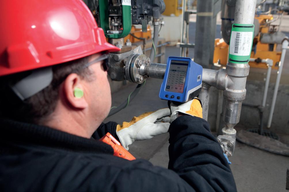
1. Define roles and responsibilities
Multiple groups are likely to be involved in a material verification programme. Make sure each group has clearly defined responsibilities in the MVP.
2. Define the programme objectives
Consider the objectives for the material verification programme to establish clear goals. Example objectives include:
) Identify a part’s alloy before putting it into service.
) Verify the alloy is correct for that service.
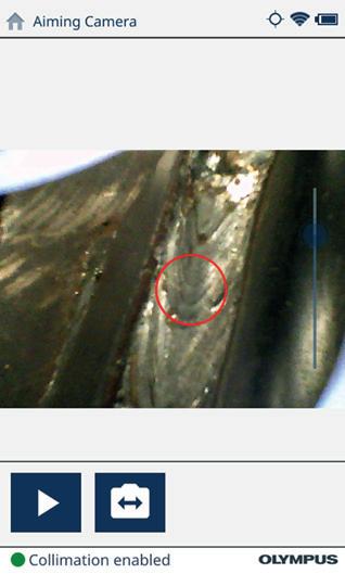
) Determine the best method for the PMI analysis required.
3. Choose your PMI testing methods
PMI is the analysis and identification of materials through various nondestructive methods. Many PMI test methods and instruments are suited for alloy identification in a material verification programme. Three primary PMI analysis instruments are handheld XRF analysers, portable spark optical emission spectrometers (OES), and handheld/ portable laser-induced breakdown spectroscopy (LIBS). Each analysis technique has its own strengths and weaknesses. Here is a brief overview of each PMI testing method:
Handheld XRF
) Uses X-ray fluorescence technology.
) Compact and easy to use.
) Analyses all but the lightest elements (e.g. carbon).
) Nondestructive: leaves no marks or blemishes.
) Variable analysis times depending on the alloy type.
Portable spark OES
) Uses the energy of a spark.
) Heavy and bulky with a long learning curve.
) Well-understood analysis technology that measures all elements of interest.
) Nondestructive but leaves a burn mark.
) Short analysis time.
Handheld and portable LIBS
) Uses laser light to create a sample plasma.
) Compact and easy to use.
Figure 2. The Vanta handheld XRF’s camera collimator feature can test a small spot.
38 World Pipelines / COATINGS & CORROSION 2021
Figure 3. Test results from the Vanta handheld XRF analyser.


Need a reprint? +44 (0)1252 718999 reprints@worldpipelines.com We can tailor to your requirements, produce 1 - 12 page formats, print colour or mono and more
) New technology that analyses most elements of interest.
) Nondestructive but leaves micro-scratches or blemishes.
) Very short analysis times.
All three technologies have a place in material verification programmes throughout manufacturing, installation, maintenance, and retroactive PMI (i.e. the testing of in-service equipment and piping systems).
4. Establish a PMI training programme
A formal PMI training programme helps ensure that your staff are trained to follow MVP guidelines and perform testing correctly. When designing your PMI testing programme, consider the following:
) Analytical technique or test method: Will you use XRF, LIBS, and/or OES?
) Instrument calibration/certification frequency and protocol: Establish protocols to help ensure your instruments are properly working and can provide the accuracy and precision needed for testing.
) Personnel qualification, knowledge, and proficiency requirements: Set up proficiency testing so your team is adequately trained.
) Surface preparation requirements and procedures: Determine the best surface treatment for the analytical technique.
) Data acceptance criteria: What are the outliers vs. acceptable data?
) Documentation requirements: Determine a proper chain of custody and documentation.
5. Establish record keeping best practices
Good record keeping is essential to meet regulatory compliance with API RP 578 and other industry standards regarding materials used in plants and refineries. Documentation must include:
) Date, time, and place.
) Testing procedure used.
) Analysis method.
) Instrument identification.
) Tested part identification.
) Report nonconformance and resolution.
) Report conformance.
) Labelled and traceable to the tested part.
Record keeping can be simplified with the right tools. For instance, XRF analysers can help streamline the record keeping process with built-in features for traceability and reporting.
The role of handheld XRF in material verification programmes and beyond
Thanks to its ease of use and versatility, one of the most popular PMI methods for a material verification programme is handheld XRF. XRF testing can provide immediate alloy verification in piping, valves, welds, components, and pressure vessels. Beyond API RP 578 compliance, XRF can also help you detect sulfidation corrosion susceptibility (API RP 939-C), evaluate flow accelerated corrosion (FAC) susceptibility, and discern residual element corrosion susceptibility in hydrofluoric acid (HF) alkylation units.
Finding the ideal handheld XRF analyser for material verification programme
If you are considering a handheld XRF analyser for material verification and PMI testing, it is important to consider the ruggedness of the instrument to maximise productivity.
A durable XRF analyser can withstand a wide temperature range and be used for in-service inspection of high-temperature systems and hot sample surfaces. Also consider the IP rating to protect against rain, dirt, and dust. Drop-tested XRF analysers can protect against falls, and a detector shutter can help prevent punctures when analysing rough surfaces. These durable features help reduce costly repairs while maximising uptime at the plant or refinery.
With a durable design, the analytical performance of XRF analysers can be used to the fullest. Modern handheld XRF technology can provide test-to-test and instrumentto-instrument repeatability. Speed is another benefit. XRF analysers with ultra-low-noise electronics provide high X-ray counts per second and fast alloy results.
User-friendly software can help speed up user training and maximise user throughput. For instance, some XRF analysers have bright touch screen displays that work like your smartphone. Just like you can modify the apps on your phone, a modern XRF analyser lets you customize which features to display on the main screen. Also look for functions that can streamline reporting and data management, such as an integrated GPS, a panoramic camera, and multiple data export options. Cloud technology can simplify fleet and data management for multiple XRF devices.
Verifying the chemical composition and grade of welds is critical for PMI testing, so look for an XRF instrument with a welding alloy library. An aiming camera can also help you accurately analyse thin weld beads and other conjoined metals. Smart features like these can help streamline your material verification and help ensure quality throughout the process.
40 World Pipelines / COATINGS & CORROSION 2021
The world’s network of pipelines is ever increasing. On a daily basis, pipe is getting welded up and put into the ground to carry a wide array of materials and often these pipes are right beneath our feet. For those of us that live in high population density locations, the likelihood that a pipeline is running under the roads we drive on, beneath the neighbourhoods we live in, and under the buildings we work in, is very high. And if there wasn’t a pipe there yesterday, there could be one there today thanks to the use of horizontal directional drilling (HDD). HDD is the process of installing a pipeline without digging a trench. HDD is used in high consequence areas, such as population dense areas, beneath structures and roads, or to span beneath waterways. It is achieved by drilling a hole deep beneath the area that the pipeline is trying to avoid disrupting, then dragging the pipeline through that hole. Figure 1 provides a general idea of what that looks like.
As you can imagine, drilling a hole in the ground isn’t as easy as it sounds. The various soil layers beneath our feet contain a wide variety of soil types, rocky layers, and random obstructions. While the drawings of an HDD are much like Figure 1 (long, smooth, curving, and uniform), the reality is that the hole can be filled with shards of
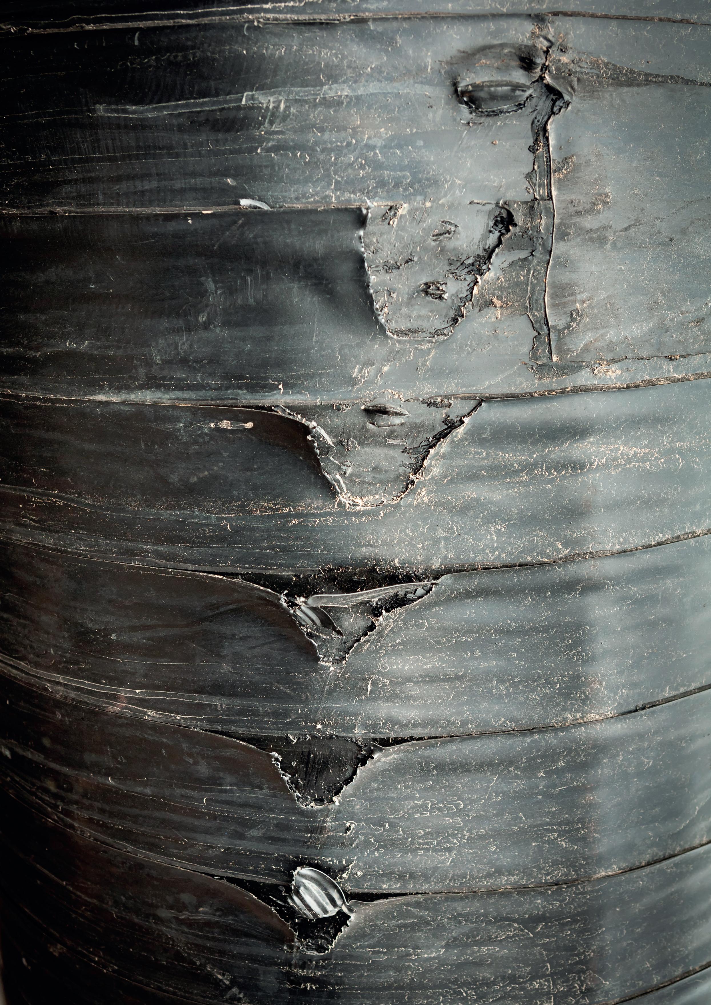 Ron Raphoon, Denso North America, outlines key considerations for protecting pipeline coatings during trenchless pipeline installation.
41
rocks, roots, sand, or any number of random objects from the ground. Beyond the items that are suspended in the hole, there are variations in the path that might move the pipe up, down, left, or right along as it is drilled. Any time the pipe moves up or down abruptly, there is the potential for the pipe to drag against the wall of the hole. Doing so can cause numerous issues, including a frac out of the hole, abrasion of the coating, bending of the steel, or shearing a coating completely off.
Pipeline damage during pullback
While the industry continues to grow and learn from its brief history, the truth remains that there are some damaged pipes and areas of protective coating worn down or removed that exist on pipelines that are lying beneath high consequence areas. The truly unfortunate part is that these pipes are inaccessible for repair. This is obvious when the reason for using the HDD method for installation is evaluated. Those sections of pipe were put into the ground in that way specifically because they couldn’t dig a trench there, meaning they can’t dig down to repair it if necessary.
This means that it is vital that the HDD path is designed well to avoid damage to the steel from bending. It also means that the cleanliness of the hole and the soil that the pipe is passed through should be of the highest concern. At the current time, American Petroleum Institute (API) has some best practices developed, as does the Pipeline Research Council International (PRCI), and other organisations are developing them as well. In reviewing best practice, they primarily focus on minimising the impacts of damage from the design aspect. API offers eight practices to improve the success rate of an HDD installation: of those eight best practices, seven of them directly address pipeline damage during pullback. What this tells us, is that they know the damage is occurring and that the installation itself is the highest risk of producing that damage.
Anti-corrosion coatings are vulnerable to damage
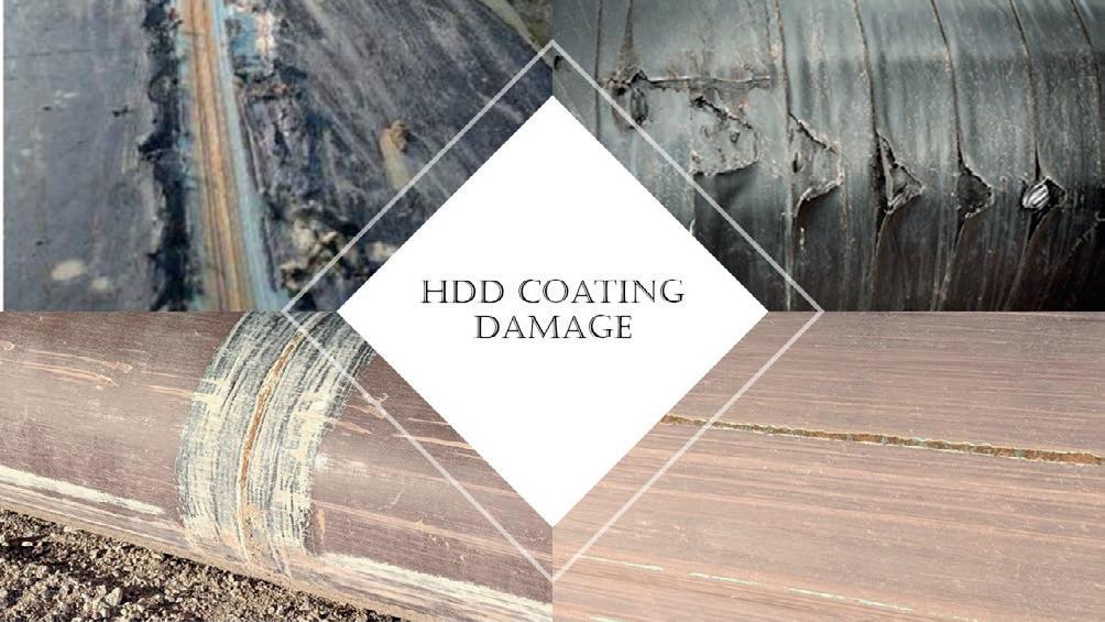
In the pipeline industry, one of the most common threats to the long-term performance of a pipeline is the presence of corrosion. This has been addressed for decades by applying anti-corrosion coatings to the outside of the pipe. When anti-corrosion coatings are in place, they can prevent corrosion that could wear through the steel and result in leaks or even possibly be the source of explosions. Unfortunately, most anti-corrosion coatings are very vulnerable to damage when the pipe is being pulled into an HDD hole. Obviously, if pulling in the pipe causes damage to the steel, it is also capable of damaging the coating. The coating is the first line of defense against a pipeline failure and as such Denso has developed coatings specifically designed to absorb and endure the hazards that are present from HDD installations. Some examples of coating damage that is seen in HDDs are shown in Figure 2.
Abrasion
In most of the images that comprise Figure 2, the drilling contractor was following best practice, yet the result of the pipeline installation was still a damaged anti-corrosion coating. Abrasion from dragging the pipe into a hole is virtually guaranteed. As such, the vast majority of coatings that are used in HDD applications have fairly decent abrasion resistance. However, abrasion alone is probably the least likely reason for complete removal of a coating resulting in exposure of the bare steel. The most common cause of coating failure comes from impact to the coating and gouging from debris or protrusions from the hole wall.
Impact and shearing
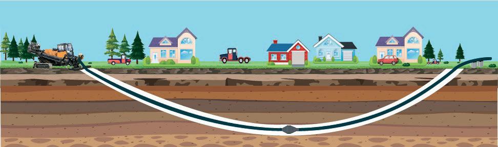
You might be asking yourself: “Where does impact take place in a horizontal directional drill?” The answer to that is fairly simple. Any elevated surface that comes into contact with a hard object in the hole as it is dragged along, will impact on the edge of the
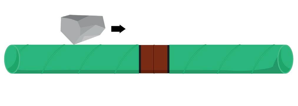 Figure 1. A typical example of horizontal directional drilling in a high consequence area.
Figure 2. Examples of coating damage as a result of HDD installation.
Figure 1. A typical example of horizontal directional drilling in a high consequence area.
Figure 2. Examples of coating damage as a result of HDD installation.
42 World Pipelines / COATINGS & CORROSION 2021
Figure 3. Showing how a gouge that passes across a weld creates an impact.
elevated surface. Elevated surfaces include weld seams, off set pipe ends, and coatings that have raised lips over the edge of a coatings (i.e. heat shrink sleeves or tapes). Many coatings have difficulty surviving impact and will commonly chip, break or tear when something like a rock hits the weld then drags over it. Sometimes that gouging will lead to shearing when a softer coating gets caught up and the pipe continues to be pulled (Figure 3).
Gouging and bending


Another common reason for coating failure is from gouging. One of the ways gouging can become an issue is along the top of the pipe when it is dragged across a curve in the hole, as seen in Figure 4. This dragging will not only cause abrasion on the surface but, as it wears away the soil, hard objects such as cobble can be exposed and can dig into the coating as the pipe is dragged along. These gouges can occur all along the length of the pipe, exposing long lengths of steel or small spots here and there. Exposure like this leads to the potential for pitting corrosion, which can be far worse than general corrosion if not properly protected. The bending of the pipe around these curves can be a source of damage as well. Many pipeline coatings are very rigid – this is typically a good quality when addressing abrasion – however rigid coatings are inflexible, especially as they increase in thickness. Unfortunately, a common practice in HDD is the increase in coating thickness, adding the possibility that a coating will crack or disbond while following the curvature of a bore hole.


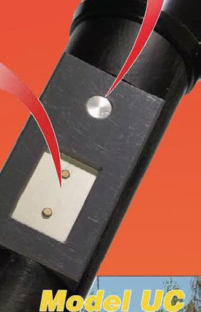
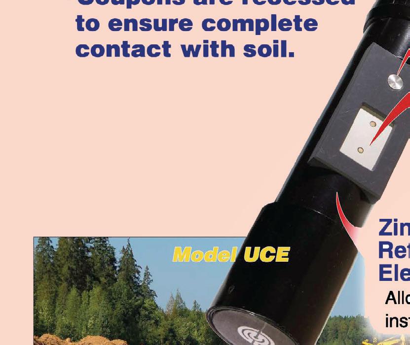

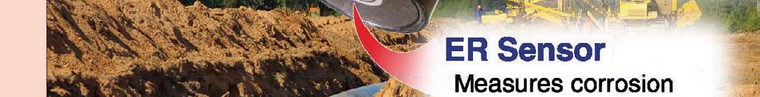

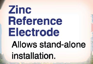
Protecting anticorrosion coatings

All of these sources of coating damage need to be mitigated to ensure that the anti-corrosion coating selected to protect the pipeline remains intact once the pipeline is installed. The previously mentioned best practices from PRCI and API
both suggest steps to minimise the source of these damages, however DensoTM has taken the precautions one step further. By understanding the causes of coating damage which continue to occur even when following best practice, Denso was able to design a protective outerwrap which addresses each cause of damage. The product, aptly named Denso Bore-Wrap™, is an outerwrap that can be used to protect all the major pipeline coating systems used in trenchless boring operations. Each component of Bore-Wrap was selected specifically to address the elements of abrasion, gouging, impact, shearing, and bending.
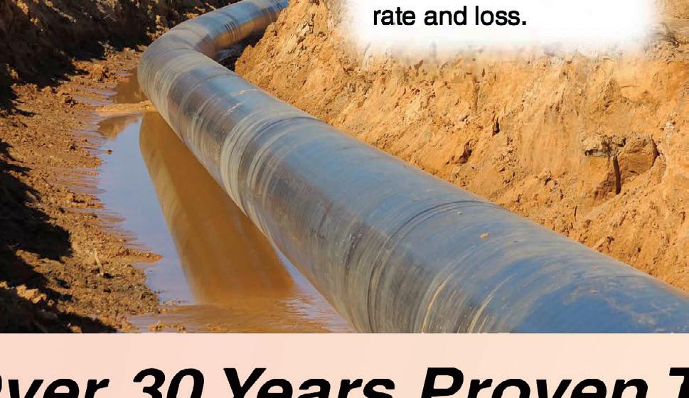
Denso Bore-Wrap is made up of several key components, each with benefits selected for their value in this application. The base of the Bore-Wrap is its under layer of woven roving (WR) fibreglass. This layer of fibreglass is composed of woven layers that run both circumferentially and longitudinally along the pipe. The woven structure provides some resistance to gouging due to the continual change in direction, but the most important factor with the WR is the fibres that wrap the pipe circumferentially. This continual stranding around the pipe offers a level of compression strength, which will resist shearing even when applied over softer coating
systems. The WR also has significant thickness which will increase the level of abrasion resistance. On top of the WR layer is a layer of continuous stranded matting (CSM) which is a long randomised mat of fibreglass that is stitched to the sub layer of WR. The CSM has omni-directional fabric so that no one angle is prone to separation and there are no lines that a gouge can naturally follow. Having so many random angles offers an incredible resistance to gouging, so much so that, when tested, the addition of this layer reduced the overall gouge depth to almost half that of five different fibre architectures used in other coating systems in the market.
Bringing all of the components together, Bore-Wrap uses a moisture-cured urethane (MCU) which, as its name indicates, cures with water. The curing of the MCU with water creates a CO2 reaction, generating a porous structure of resin holding the fibres together while simultaneously offering incredible flexibility. By having a porous structure, Bore-Wrap is able to offer a higher level of flexibility than fusion bonded epoxy (FBE), which is the most common underlying anti-corrosion layer on the pipelines. The MCU cures and bonds each layer together into one large homogeneous outerwrap. The porosity of the structure also offers two invaluable benefits. Firstly, it is very impact resistant, in orders of magnitude higher than most pipeline coatings. Secondly, it allows more moisture to be absorbed and it has very low electrical resistivity. This allows for Bore-Wrap to act similarly to the soil surrounding the pipe and thus it will not shield cathodic protection from doing its job.
All of these claims sound great in theory and much consideration was put into the elements, including how they interact and how they are applied. While Bore-Wrap is easy to apply and simple to understand, its performance is all that matters to the pipeline owner or the contractor tasked with dragging a pipe into a bore hole. Since the development of Bore-Wrap, it has been used on pipelines of small diameter and large diameter. Bore-Wrap has been applied over FBE coating, liquid epoxy, and wrapped over PE coated pipe. Denso has offered this product across the globe and it has been applied to protect vulnerable field joints, elevated weld seams, and also to encapsulate the entire lengths of pipe that were installed by HDD.
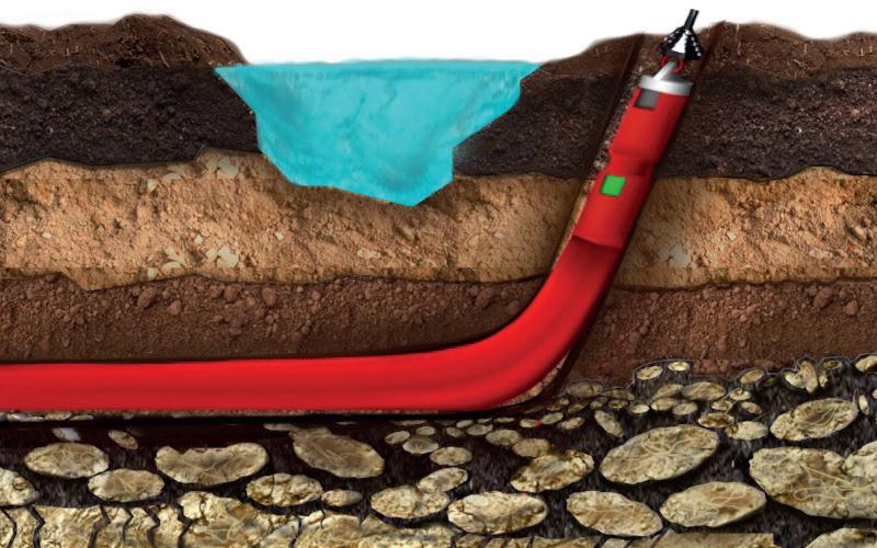
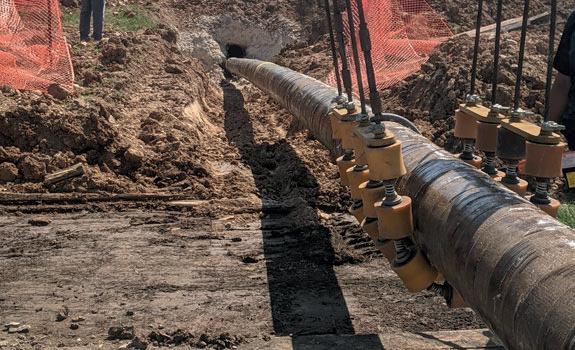
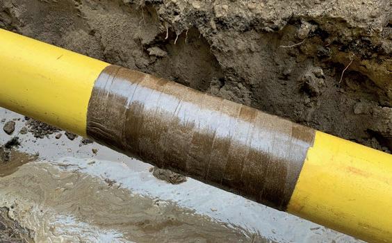
Conclusion
Denso Bore-Wrap has even been used and applied over the top of other products labelled as abrasion resistant outerwrap (ARO) products. While those products are already abrasion resistant, abrasion isn’t the most detrimental source of damage by any means. Denso Bore-Wrap is an ARO, but it is also an impact resistant outerwrap, a gouge resistant outerwrap, and a shear resistant outerwrap. Perhaps the industry needs to re-evaluate its need for an ARO and instead recommend a shear, abrasion, impact, and gouge (SAIG) resistant outerwrap. Bore-Wrap is a solution that benefits society, not just the pipeline operator. Bore-Wrap is also an excellent tool for a pipeline contractor to ensure they are offering the best protection for their customer and saving themselves from the difficulty and expense that comes from a re-pull of the pipe should the coating fail the inspection after getting dragged in a hole beneath our homes, businesses, waterways, and roads. Until the industry does begin the practice of applying SAIG outer wraps, Denso Bore-Wrap will continue to offer all of these protections, keeping the pipeline beneath our feet protected as it is installed.
Figure 6. Denso Bore-wrap™ used to protect field joints during HDD installation.
Figure 4. Turns in an HDD can force the pipe to wear along the walls of the hole.
44 World Pipelines / COATINGS & CORROSION 2021
Figure 5. Denso Bore-wrap™ used to encapsulate the entire length of pipe during HDD installation.
The greatest weapon available to us, in the ongoing and escalating battle against corrosion in the network of pipelines spread across our ocean floors, is technology.More than half a century since the first rigs appeared off the coast of California, in the North Sea, across the Gulf of Mexico and around the world, much of that original pipeline infrastructure laid down to carry its valuable cargo around the world is still with us.
Functioning well beyond their intended service life, these pipelines are more susceptible to the consequences of ageing and, while there are many pipeline failure modes, corrosion is uppermost among the hazards of old age.
Since those early days we have seen ongoing, steady improvements. New materials have been introduced, pipeline design which takes greater account of the seabed terrain on which they sit is more sophisticated and the way in which pipelines are constructed, operated and maintained is much more efficient.
And while corrosion protection, mitigation and inspection technologies have all improved alongside that, it doesn’t change the fact that the longer a pipe is in service, the longer it has had for corrosion to begin and build up. This is particularly true for the older pipelines which were installed prior to the development of these more advanced technologies.
Coupled with this, the marine environment can be harsh and unforgiving in its treatment of pipelines, so monitoring and maintaining their integrity – whatever their age – is paramount.
New technologies
As pipelines continue to age, the decades of expertise built up in the subsea inspection sector is providing strong foundations on which the research and development of innovative, new, disruptive technologies is built.
These new technologies, which respond to the ever-changing problems and challenges of internal and external monitoring, are crucial in assessing and assuring the integrity and safety of pipelines, detecting loss of
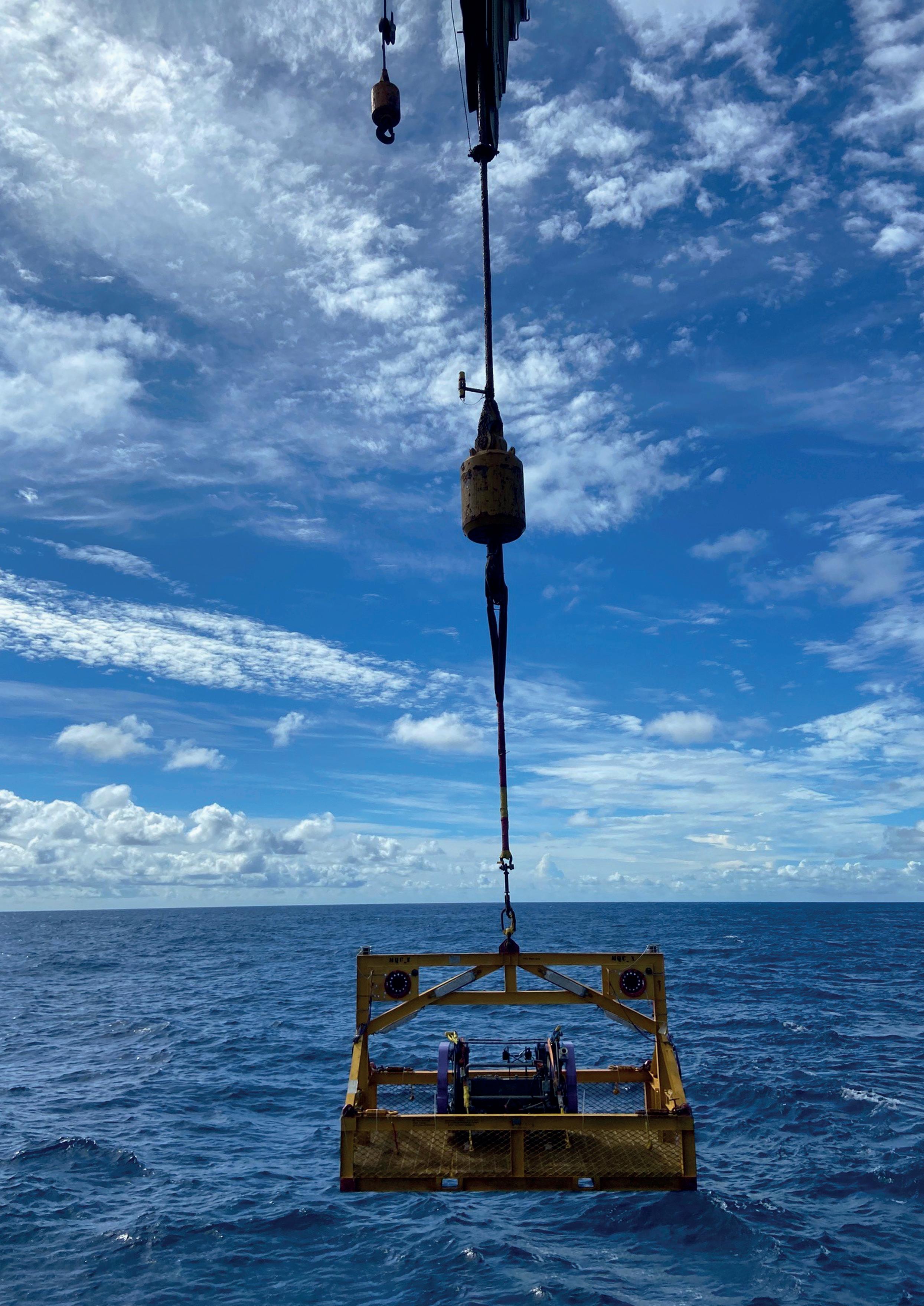 Paul Chittenden, TSC Subsea, looks at how innovation in the underwater inspection sector
is helping to solve the challenges of
subsea pipeline corrosion.
45
Figure 1. ARTEMIS® being launched offshore.
pipe wall, pinholes and leaks before issues escalate to a worst case scenario situation.
With this legacy of ageing pipelines which grow older by the year, the need for more intelligent and efficient methods of inspection and corrosion mapping is paramount.
The subsea inspection sector thrives on challenges; driven by a culture of innovation and the agility to adopt, adapt and develop new technologies where none exists. Where there are problems, it finds solutions.
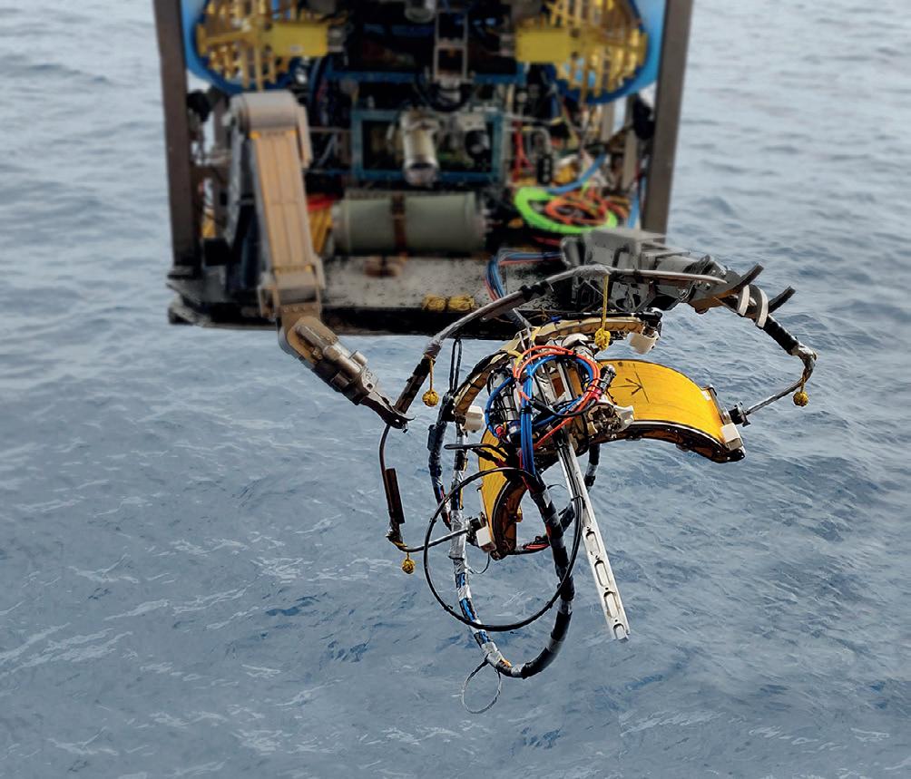
Up to 40% of the world’s pipelines are unpiggable. Unpiggable pipelines pose an even greater challenge. Before the latest in modern inspection technology was available, these pipelines were notoriously expensive to inspect and the quantity and quality of the data was minimal.
The rise of the machine in the form of ROVs and AUVs is helping us push the boundaries of subsea inspection further than ever before. Technological advances in underwater robotics mean that even in the harshest, most challenging conditions, underwater inspections can be carried out quicker, more effectively and more accurately than ever before with data gathered being transmitted for analysis by a team working remotely half a world away.
The solution to the problem of inspecting not only unpiggable pipelines, but carrying out inspections through difficult-to-penetrate anti-corrosion came literally in ART form – acoustic resonance technology. Long acknowledged as a game changer by the subsea inspection community, its technology enables inspections through coatings.
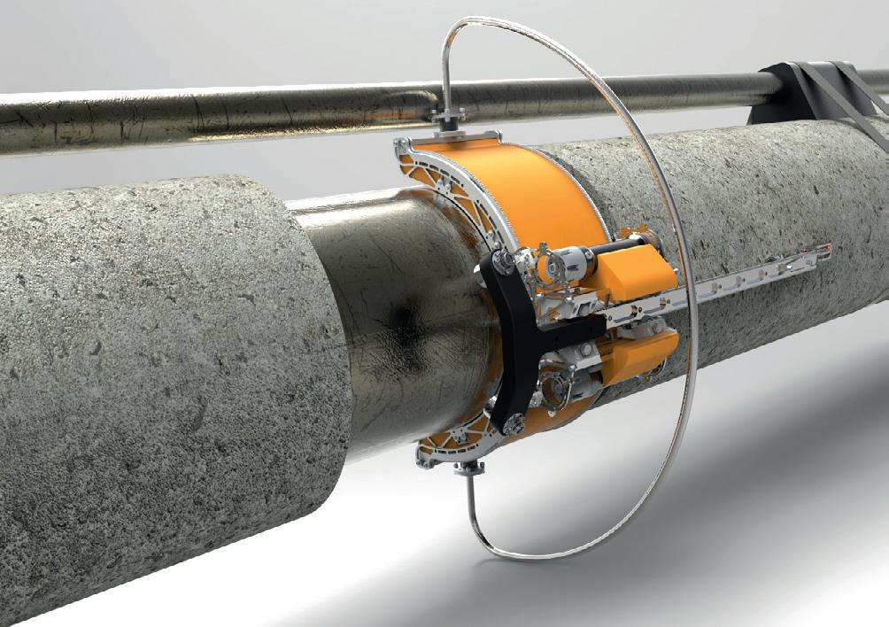
Technology has provided the solution, but technology comes at a cost. The use of an ROV to deploy inspection tooling incurs considerable expense, facing the sector and its customers with a challenge; how to collect the vital, highly accurate, usable data which is needed while balancing the inspection budget. Were there ways to lower the cost of deepwater inspections, by, for example, faster scanning and reducing dredging requirements? How could we overcome the problem of the thicker coatings typically found on deepwater pipelines? Could these inspections be done without removing coatings?
As a sector, we constantly look at what we can do better, what we can improve on, how can we improve on efficiency, be more cost effective, and improve safety.
Acoustic resonance technology
In response to those challenges, TSC Subsea developed and patented the next generation of ART technology. It employs ultra-wideband acoustic inspection technology and exceeds previously existing technologies with its much greater capability for penetration and measurement. In addition to analysing the material resonances, the technology uses time-of-flight measurements which provide accurate external geometry measurements for ovality and dents.
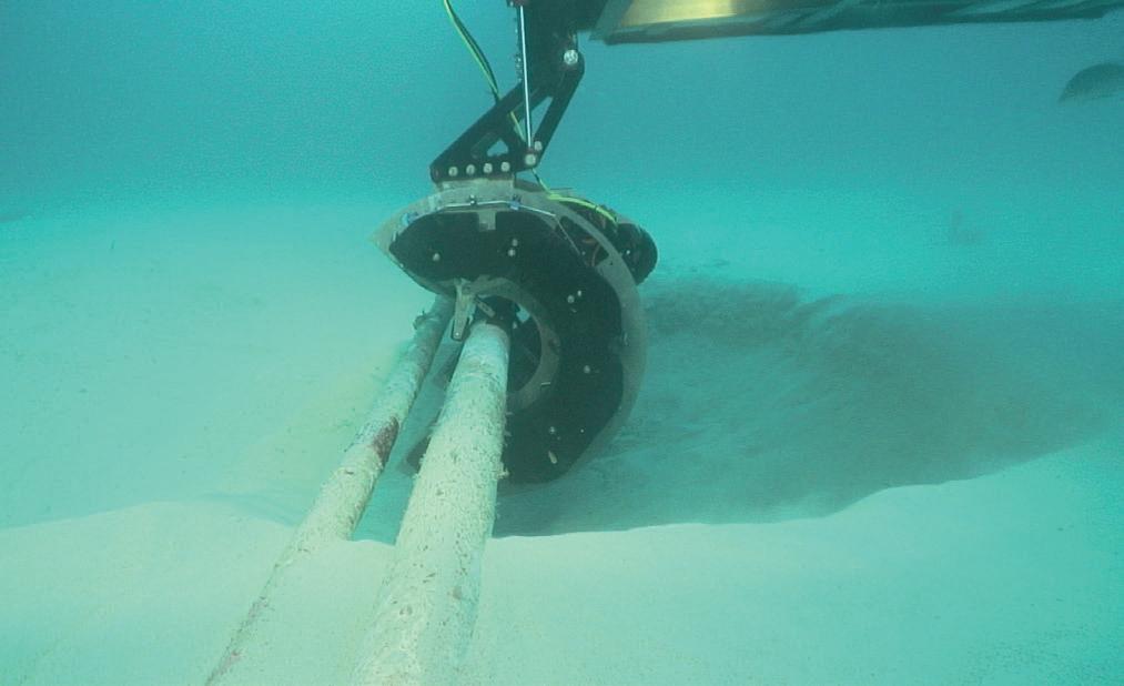
ART was originally incorporated in ARTEMIS®, TSC Subsea’s subsea external pipeline and riser inspection system. Deployed by ROV, it can carry out full circumferential scan in a fraction of the time of less sophisticated technologies, and reduces the need for dredging, resulting in considerable cost savings for the customer.
ARTEMIS® has been used successfully on multiple subsea assets, including pipelines, risers, and subsea jumpers. However, sometimes a custom solution is needed to reach previously inaccessible areas. When unexpected problems arise, solutions must be found.
Figure 2. ARTEMIS® performs subsea inspection.
Figure 3. ARTEMIS® vCompact with acoustic resonance technology (ART).
46 World Pipelines / COATINGS & CORROSION 2021
Figure 4. ARTEMIS® vCompact 3D Render.

Project case study
Unsolvable isn’t a word that features in the vocabulary of the subsea inspection community or the wider subsea supply chain. Every problem, as they say, is an opportunity in disguise. This was brought home to us recently when TSC Subsea was contracted to carry out a wall thickness inspection on the 20 in. Otway pipeline near the Thylacine A platform in Australia’s Bass Strait.
The purpose was to establish the size and depth of corrosion which had been detected during a previous inline inspection (ILI). Pipeline joints were positioned above rock and coral at a depth of 100 m, so a diverless inspection by ROV was required. The placement of the joints also meant the inspection would have to be carried out within a very narrow field joint section. Hard to penetrate anti-corrosion coating on the field joint ruled out conventional ultrasonic inspection, meaning that the inspection had to be carried out using ART.
However, our standard ARTEMIS system was too wide to fit accurately into the confined space. Within six weeks our in-house team came up with a solution. In that timescale, it designed, developed and build the ARTEMIS vCompact, a smaller, more agile version of ARTEMIS which would meet the parameters of the job by addressing the issue of tight access inspections.
Developed in response to a particular problem for a client, it has resulted in a new tool that can be used in a number of applications and which is a great addition to our diverless inspection portfolio. It was a fine example of the innovation which has guided and grown our sector over the past decades. Problems and challenges which arise, often without much warning, are being resolved every single day.
Conclusion
As we look to the future, we know we will encounter new challenges and problems. But we can be confident too, that as a sector our ingenuity and innovation will resolve those problems and each solution will bring new opportunities.
Many of those new opportunities will arise as we progress to the next era of energy generation along the energy transition journey. Despite current controversies, the oil and gas industry will remain a crucial part of that transition for decades to come, safeguarding energy security in countries around the world.
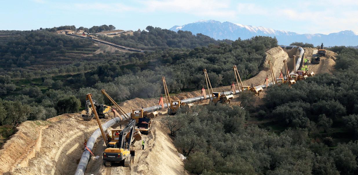
Alongside that and well into the future, we will see the exponential growth of the blue economy. The expertise honed and developed by the underwater engineering community and the supply chain in supporting the subsea pipeline infrastructure will be a critical component in advancing and supporting the emerging sectors operating in the blue economy.
Corrosion is not unique to pipelines and the technologies which have been developed, and will continue to be developed, have the potential to be transferable to sectors such as offshore wind, wave and tidal energy, aquaculture and defence.
Developments in technology over the past 50 years and more have taken us to places we might not have imagined. It will be exciting to see where the next 50 years take us.
DIRECTORY
Page 3X Engineering 2 ABC 47 AMPP 12 CRC-Evans OBC Dairyland 27
21
15
Devices,
43
Inspection
T.D. Williamson 19 Winn & Coales International
For more news visit: www.worldpipelines.com Keep up to date with us to hear the latest pipeline news Keep Updated
ADVERTISERS’
Advertiser
DeFelsko
DENSO GmbH OFC,
Electrochemical
Inc.
Girard Industries 25 Global Hydrogen Review 37 Hydrocarbon Engineering 4 LNG Industry 31 Pigs Unlimited International LLC 21 Pipeline
Company 25 ROSEN Group IFC
Ltd 9 World Pipelines 39, IBC
The print issue is distributed to a global audience of industry professionals (verified by ABC). Register to receive a print copy here: worldpipelines.com. magazine/world-pipelines/register


Prefer to read the issue online? The digital flipbook version is available here: worldpipelines.com/magazine/world-pipelines
Download the World Pipelines app for Android (Google Play) or iOS (App Store) to access World Pipelines from your mobile device.

Wherever you are, World Pipelines is with you. www.worldpipelines.com
Pipeline Induction Heat (PIH) provide specialist field joint coating services at spool base locations, offshore pipe lay barges and onshore pipeline construction projects around the world, involving the use of stateof-the-art equipment and processes for the application of a wide range of field joint coating materials.

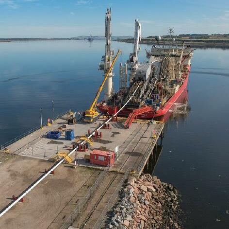


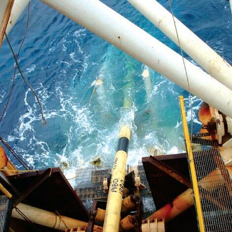
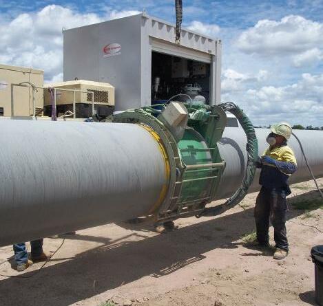
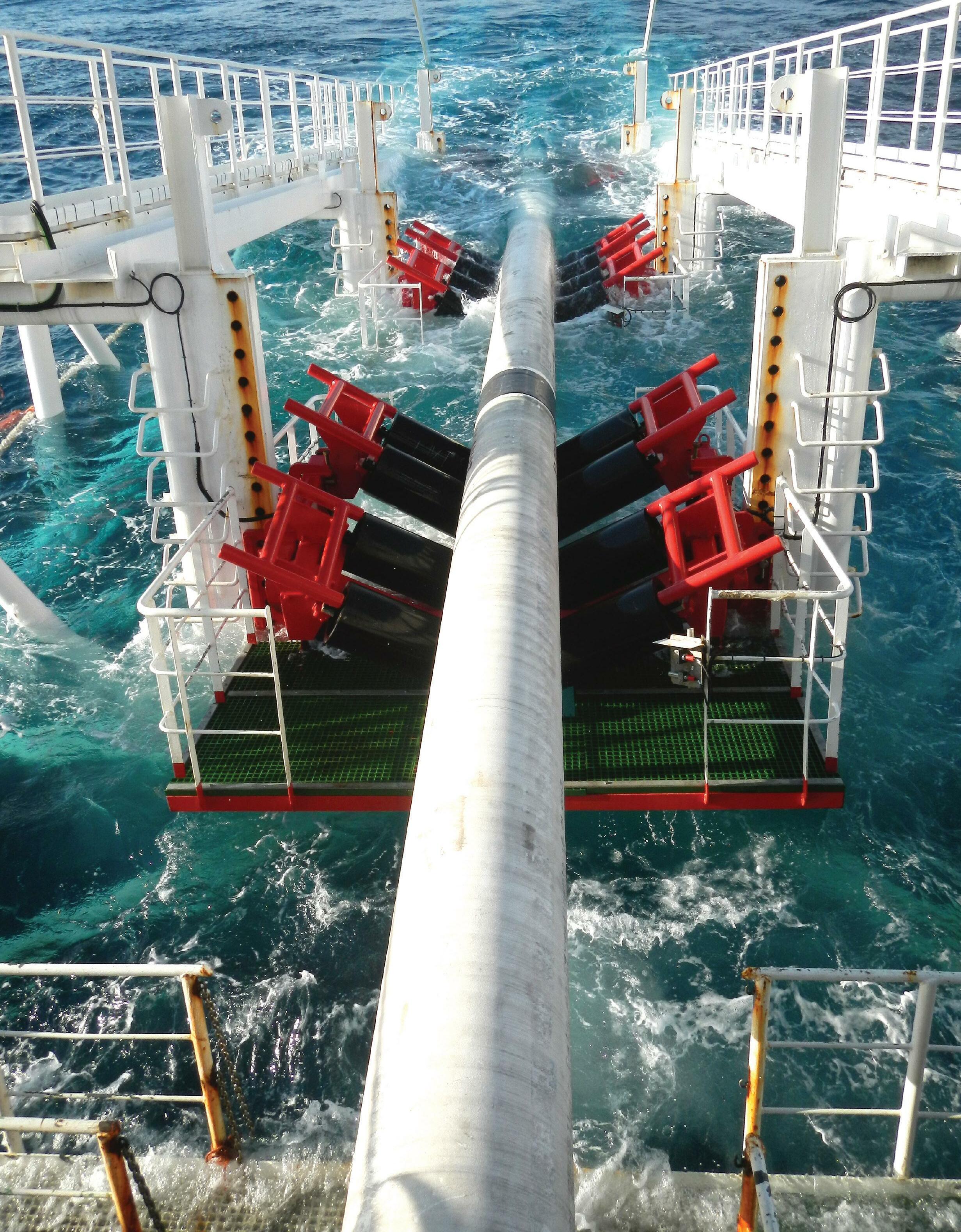
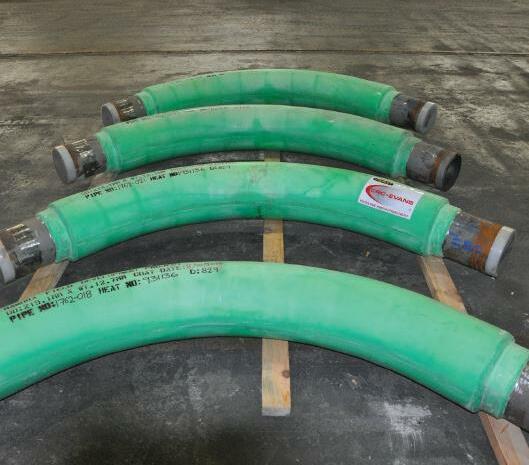
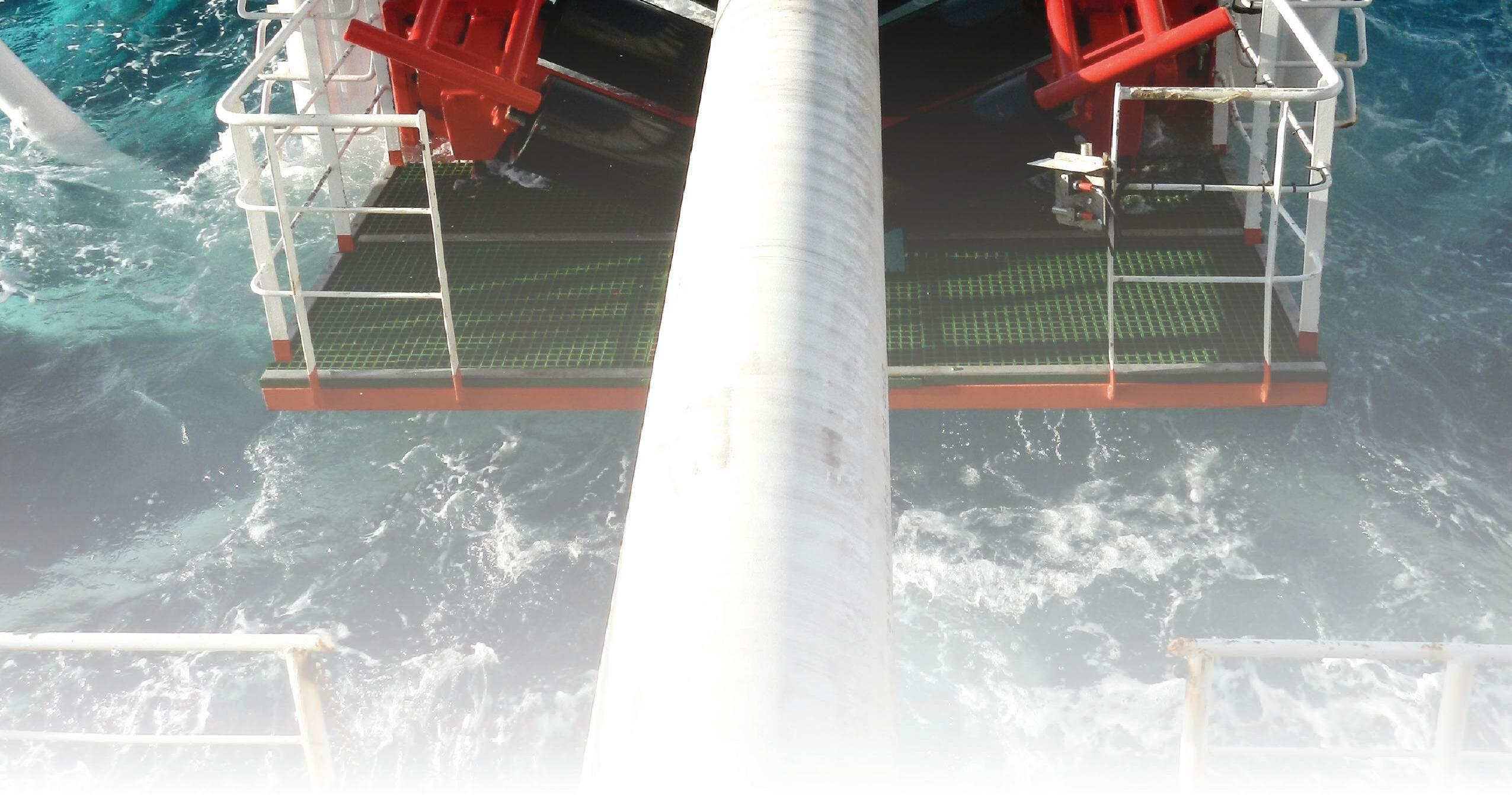
PIH also provide Custom Coating services for the application of the latest Thermal Insulation solutions (IMPP and IMPU) to bends and spools.
Field Joint Coating and Custom Coating Services
Innovation Integrity Offshore Onshore Spoolbase Custom Coating Pipeline Induction Heat Ltd, Burnley, UK Tel: +44 (0) 1282 415 323 Fax: +44 (0) 1282 415 326 E-mail: sales@pih.co.uk Web: www.pipelineinductionheat.com
Dedication