ENERGY GL BAL

ENERGY GLOBAL
CONTENTS AUTUMN 2025
03. Comment
04. Capped ambitions
Ashutosh Padelkar, Research Lead at Aurora Energy Research, maps out why the wholesale price cap is detrimental to the energy transition in India.

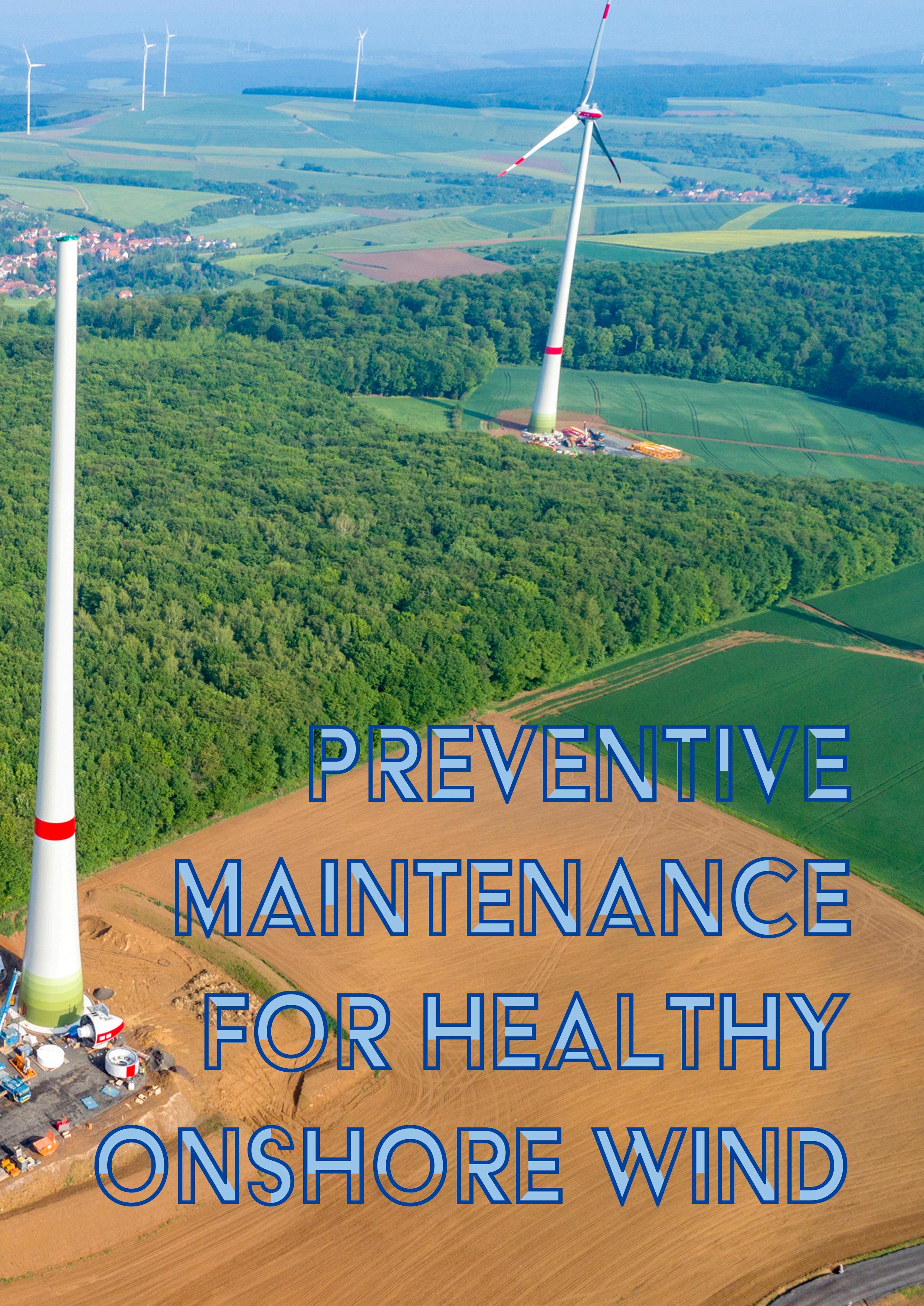
08. Preventive maintenance for healthy onshore wind
Kleopatra Kyrimi, Sarens, illustrates how preventive maintenance forms a crucial aspect of guaranteeing efficiency and reliability in the growing global onshore wind energy sector.
14. Knowledge is key
Jens Wulff, CEO EMEA & India, NEUMAN & ESSER, Germany, outlines how an understanding of the whole hydrogen value chain can help reach the growing demand for high-purity hydrogen.
18. Leading the change
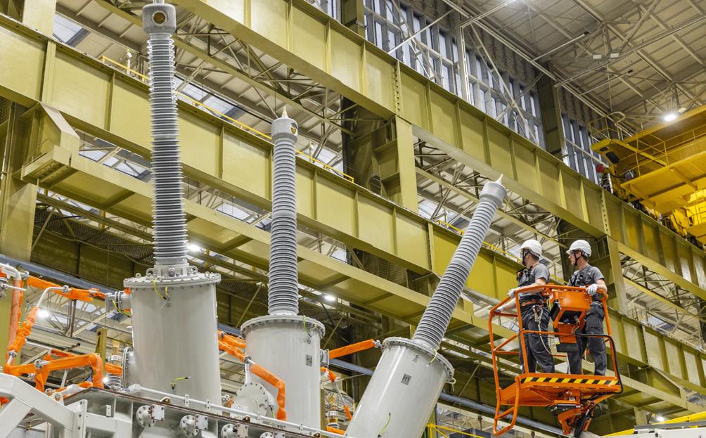
In a conversation with Energy Global, Bruno Melles, Managing Director of Business Unit Transformers at Hitachi Energy, explores how transformer technology is shaping a more resilient, efficient, and sustainable energy system.
24. Digital insights for greener winds
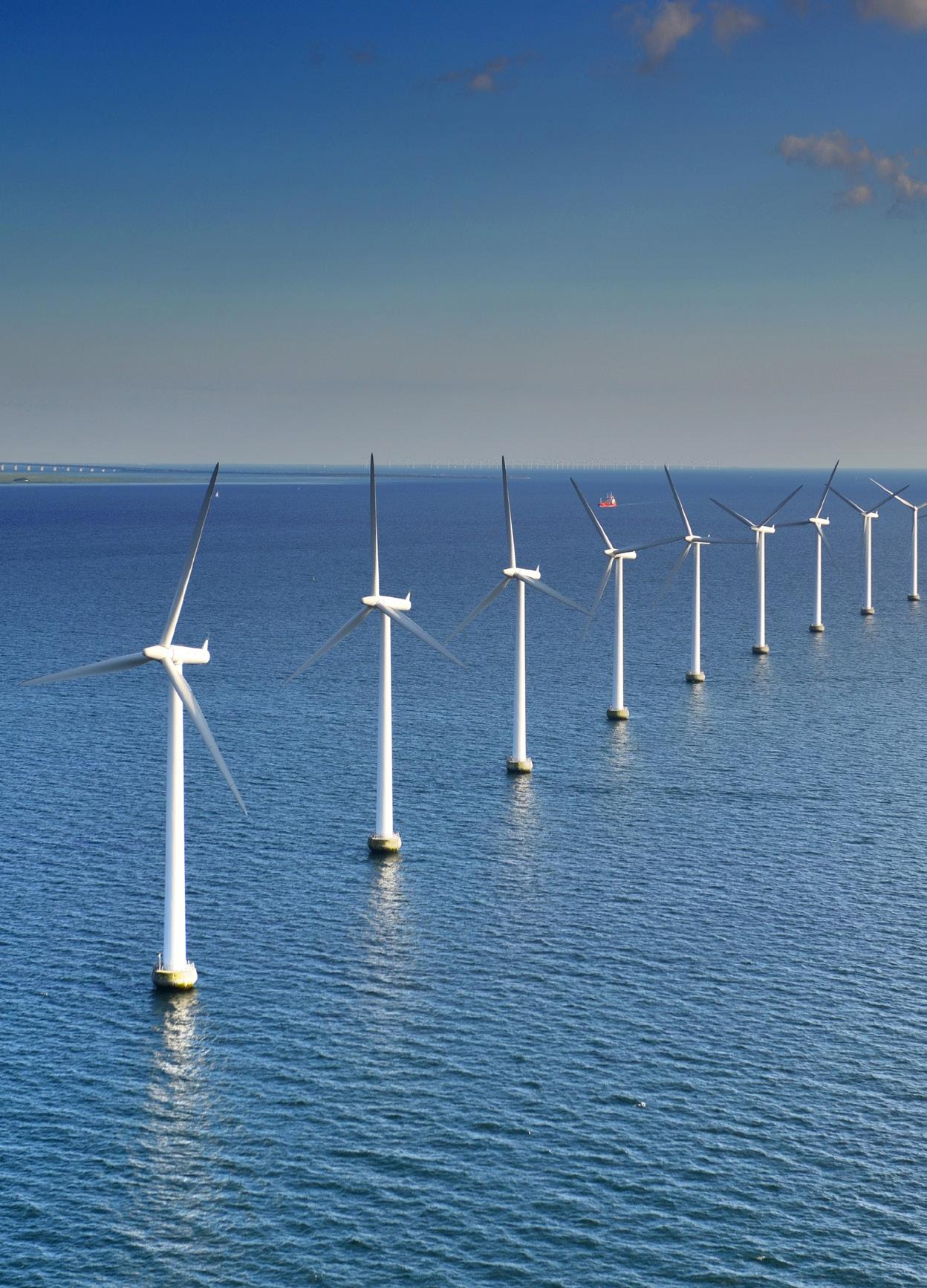
As the offshore wind sector develops, Sarah McLean, Lead Content Manager, and Drashya Goel, Senior Client Success Manager, Spinergie, delve into how digital reporting forms a crucial next step in tackling emissions at each stage of the wind farm lifecycle.
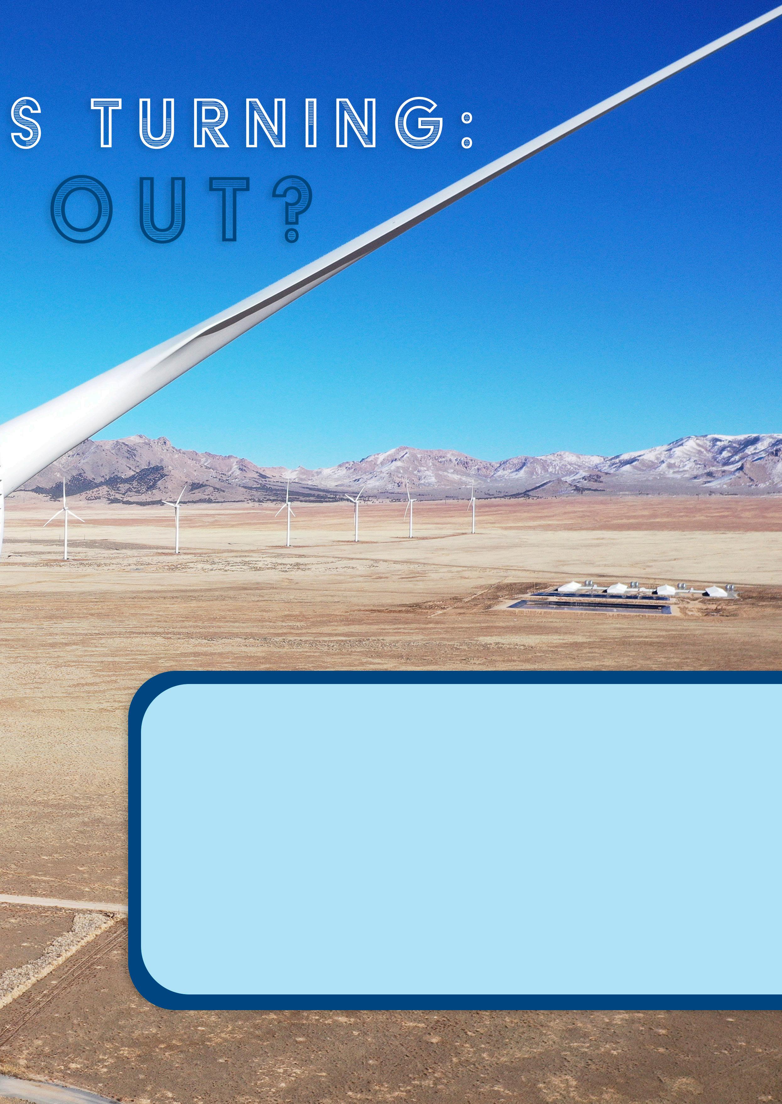
30. Keeping turbines turning: Inside or out?
The profitability of wind turbines is determined by productivity and availability. Condition monitoring supports maintenance decisions, identifies potential cost savings, and avoids unforeseen failures. David Futter, Condition Monitoring Consultancy at

Reader enquiries [enquiries@energyglobal.com]
ON THIS ISSUE'S COVER
Bachmann Monitoring GmbH, and Frank Fladerer, Bachmann electronic GmbH, compare the advantages and challenges of doing this in house or through an external partner.
36. Planning aspects for sustainable corrosion protection of offshore wind
Andreas Hoyer, Global Commercial Director of Energy & Infrastructure, Teknos, decodes corrosion protection for the offshore wind industry, surveying coating techniques, reviewing various standards, and evaluating the effectiveness and risks associated with different coating types.
40. Anchoring the future
By 2030, wind power is anticipated to supply the bulk of the UK’s green electricity, with a significant portion of this generated by offshore installations. But innovation could help the UK make use of its exceptional offshore wind resources sooner. Alun Jones, Reflex Marine, and Laurie Thornton, MintMech, discuss a novel anchor system that could set new standards for mooring technology.
44. Floating offshore wind: Filled with promise and potential
Sille Grjotheim, Global Segment Director, Floating Offshore Wind, and Alireza Bayat, Principal Consultant, Energy Systems, DNV, provide an overview of the evolution of floating offshore wind from concept to deployment.
48. Charting a path forward for the UK's floating offshore wind sector
Matt Green, Green Volt Project Director, details the importance of floating offshore wind for the UK’s renewable energy targets and sketches out the path ahead.
52. A potential power shift: Coal plants to thermal storage
Svante Bundgaard, CEO, and Jens Taggart Pelle, Vice President of Technical Sales, Aalborg CSP, advocate for the conversion of coal-fired power plants into thermal storage facilities for renewable energy, saving time and costs towards advancing the energy transition.
56. Global news
ENERGY GL BAL
NEUMAN & ESSER stands as the industry’s reliable partner, propelling the energy transition and the circular economy through its integrated solutions for the energy infrastructure of tomorrow.
The product portfolio of NEUMAN & ESSER includes compressor solutions, as well as hydrogen production systems such as electrolysers, steam reformers, holding the key technologies for future demands of clean energy.

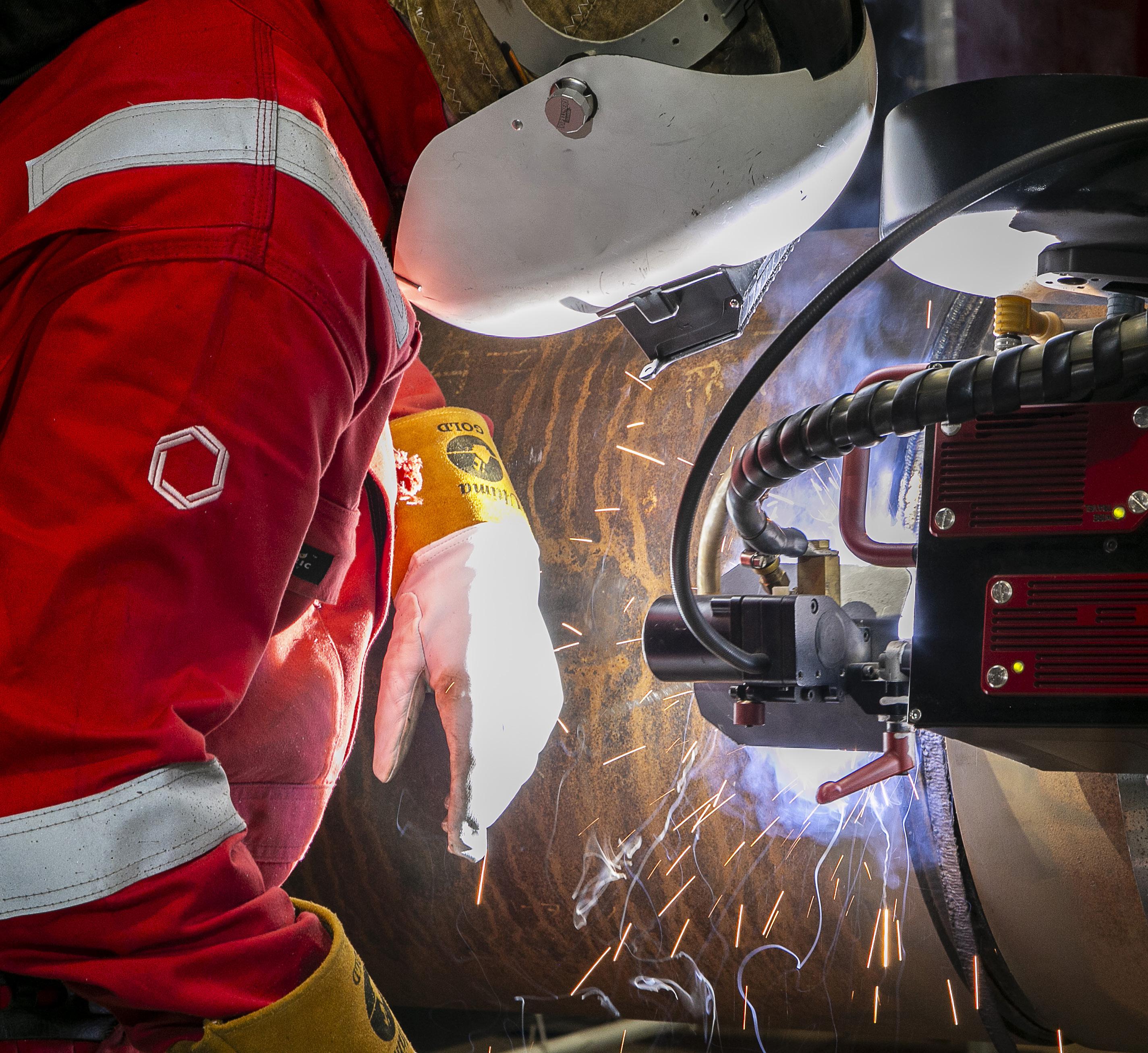
Still pioneers.
Across energy and critical infrastructure, we bring expertise where complexity is highest, partnering with globally local teams and leveraging unrivalled proprietary technologies. Like the M-500 Single Torch External Welding System, seamlessly integrated with Data 360 our cloud-based digital platform that analyses, and visualises your project performance data in real time. We move projects forward, no matter the challenge. We’re here to partner on how our specialist welding and coating solutions can help you power tomorrow.


MANAGING EDITOR
James Little james.little@palladianpublications.com
SENIOR EDITOR
Elizabeth Corner elizabeth.corner@palladianpublications.com
EDITOR
Jessica Casey jessica.casey@palladianpublications.com
EDITORIAL ASSISTANT
Abby Butler abby.butler@palladianpublications.com
SALES DIRECTOR
Rod Hardy rod.hardy@palladianpublications.com
SALES MANAGER
Will Powell will.powell@palladianpublications.com
PRODUCTION DESIGNER
Siroun Dokmejian siroun.dokmejian@palladianpublications.com
HEAD OF EVENTS
Louise Cameron louise.cameron@palladianpublications.com
EVENT COORDINATOR
Chloe Lelliott chloe.lelliott@palladianpublications.com
DIGITAL EVENTS COORDINATOR
Merili Jurivete merili.jurivete@palladianpublications.com
JUNIOR VIDEO ASSISTANT
Amélie Meury-Cashman amélie.meury-cashman@palladianpublications.com
DIGITAL ADMINISTRATOR
Nicole Harman-Smith nicole.harman-smith@palladianpublications.com
DIGITAL CONTENT COORDINATOR
Kristian Ilasko kristian.ilasko@palladianpublications.com
ADMINISTRATION MANAGER
Laura White laura.white@palladianpublications.com
Editorial/Advertisement Offices: Palladian Publications Ltd
15 South Street, Farnham, Surrey, GU9 7QU, UK +44 (0) 1252 718 999 www.energyglobal.com
COMMENT
Jessica Casey Editor
Autumn is creeping its way to the UK – the rainy weather, slightly colder temperatures, and the beginning of darker evenings are all signs that the end of the year is coming
Grid stability will remain crucial in helping provide energy in periods of high demand. One way this can be achieved is the use of battery storage and co-location with solar and wind farms to help with grid flexibility and security. The UK in particular has made a recent push towards shining a spotlight on the future role of energy storage. For example, EDF and Ampeak Energy have signed a long-term agreement to optimise the AW1 battery energy storage system in South Wales. The 120 MW/240 MWh facility will store electricity and release it to the grid during periods of high demand, supporting the balance of supply and demand while helping the UK reach emissions targets.1 Moreover, Equitix has formed a consortium with Aware Super and the National Health Fund to invest £500 million into a new UK battery storage platform, Eelpower Energy. The business will build, own, and operate grid scale battery storage assets and aims to deliver over 1 GW of new battery storage capacity for the UK grid in the coming years.2
More widely, 3E has completed a milestone in the flexibly utility scale energy storage (FULLEST) research project, delivering a digital twin technology for battery energy storage systems, with Vrije Universiteit Brussel. The project addresses critical challenges in the expanding European energy storage market.3
Another sector which the UK is investing in to help achieve net zero is floating offshore wind. While newer than fixed foundation technology, the floating offshore wind market has grown in popularity in recent years. The UK is already well-established as a leader in this; floating turbines in British seas alone open up a potential resource of over 1500 TWh/y.4 In addition, building out just the UK pipeline
of floating projects needed to reach net zero could have the potential not only to help meet energy needs, but also contribute £25 billion to the UK economy and employ 100 000 people.4
The Autumn issue of Energy Global touches on this developing technology, with multiple articles from industry leaders. DNV provides an overview of the evolution of floating offshore wind, from concept to development. The article considers some potential barriers to scaling up floating offshore wind, and looks at factors that might help secure a floating future. Green Volt outlines the importance of floating offshore wind for the UK’s renewable energy targets, drawing on how projects such as Green Volt can help pave the way for future projects. Finally, MintMech and Reflex Marine discuss a new anchor system that tackles both the technical obstacles and the practical and economic realities of scaling up floating offshore wind installations.
Whichever direction floating offshore wind takes, Energy Global will be with you every step of the way. I hope you enjoy the issue.
References
1. ‘EDF and Ampeak Energy sign a long-term agreement to optimise flagship AW1 battery project’, EDF, (1 September 2025), www.edfenergy.com/ media-centre/edf-and-ampeak-energy-sign-longterm-agreement
2. ‘Equitix-led consortium with Aware Super and the National Wealth Fund launches a £500 million platform to build, own, and operate UK battery storage assets’, Equitix, (27 August 2025), https://equitix.com/news/equitix-led-consortiumwith-aware-super-and-the-national-wealth-fundlaunches-a-500-million-platform-to-build-own-andoperate-uk-battery-storage-assets/
3. ‘FULLEST project delivers advanced digital twin technology for Battery Energy Storage Systems (BESS)’, 3E, (18 August 2025), www.3e.eu/resources/ news/fullest-project-delivers-advanced-digital-twintechnology-for-battery-energy-storage-systems-bess
4. ‘Floating Wind: Anchoring the next generation offshore’, UK Floating Offshore Wind (FLOW) Task Force Phase 2, (8 October 2024), www.renewableuk. com/media/scccdrxe/floating-offshore-wind-2050vision-final.pdf

Ashutosh Padelkar, Research Lead at Aurora Energy Research, maps out why the wholesale price cap is detrimental to the energy transition in India.
After being shown the profitability potential of utility scale battery energy storage system (BESS) projects that arbitrage the price differences within a day, a lender asks: “Sure, these returns look great – but what if the price cap is revised downwards?” At over INR 7.5/kWh on average throughout 1H25, the spreads (or difference between the highest and lowest prices in the power exchanges in a day) are attractive. However, the banker was right to be concerned: the price cap was initially set at INR 12/kWh in April 2022, but was revised down to INR 10/kWh the following year. If the government were to move the cap down to INR 8/kWh, the spreads would decrease by over 25% – this represents a risk few lenders would take.
Why a price cap?
The price cap in the Indian power market was introduced to help increase the affordability of electricity for consumers,

in response to the high prices seen in early 2022 during the energy crisis. As the average prices in March 2022 exceeded INR 20/kWh, the government stepped in and capped them to INR 12/kWh, a level at which they remained for the following six months. As the Indian government tried to expand access to electricity, concerns around affordability of power rightly drove action. However, prices have since continued to decline. Although the cap was lowered to INR 10/kWh in 2023, there has been no month since September 2022 when the average prices have remained at the cap. While there have been many instances of prices remaining at the cap for several hours on end, the wider trend for the last three years has been a decline in prices.
The rise of renewables
This decline in prices is driven by the deployment of renewables, primarily the expansion of solar energy. The installed capacity of solar photovoltaics in India has doubled
from 54 GW at the beginning of April 2022 to 111 GW as of May 2025. While the business models utilised by these projects would differ – some would be backed by tenders, others might have C&I contracts or sell in the exchange – the common thread is that the generation of solar peaks at the middle of the day. This leads to an oversupply of power in those hours, and consequently the price declines: the prices in the exchanges between 10 am and 2 pm have declined from INR 4.2/kWh in 2022 to INR 2.9/kWh in 2024.
This decline in prices continued into 2025, especially driven by sluggish economic growth leading to a slow rise in power demand and spooked investors and developers alike when prices approached INR 0/kWh for several hours a day in May and June 2025. A range of factors drove prices down: the early arrival of monsoons in India led to lower demand for air-conditioning, DISCOMs had excess power they were selling in exchanges at low prices to avoid paying deviation settlement mechanism (DSM) penalties, and thermal plants were already running at their minimum stable generation levels and could not further decrease their generation if they were to be available for the evenings.
However, even as the prices touched INR 0.30/kWh for several hours a day every day between 22 – 28 May 2025, these days also saw prices touching the cap of INR 10/kWh for several hours around midnight. Essentially, what the Indian power market is facing is not low power prices as has been widely discussed, but rather volatile power prices: the average spreads in that week were INR 9.1/kWh, 21% higher than the average in 1H25. This diagnosis calls for the deployment of storage as the primary solution – the excess power in the middle of the day must be moved to the evenings when there is higher demand.
While the need for storage in India is abundantly clear, the equally obvious barriers preventing its deployment remain; the price cap that prevents exchange prices from exceeding INR 10/kWh being the key obstacle. One solution introduced by the government was the high price market, which has a higher cap, but this market is plagued by much lower liquidity and consequently does not offer a practical solution that would offer comfort to investors.
Building investor confidence is vital as India aims to decarbonise its power system and rapidly scale up renewable energy: by 2030, in addition to expanding thermal generation, solar would need to be doubled again to nearly 230 GW of installed capacity, and the system would need nearly 60 GW/200 GWh of storage according to Aurora’s projections. This represents a CAPEX of nearly INR 6.6 trillion (US$80 billion), and this capital would come from both domestic and international investors seeking stable returns. Regulatory uncertainty in the form of this price cap, particularly with the risk of it being moved down, is detrimental to giving investors confidence in investing in the Indian power sector.
What are the solutions?
The solution that would build investor confidence is the complete removal of the price cap, along with a commitment to not introducing it again. This would bring forward the deployment of batteries that participate in the power exchanges, in contrast with those that are contracted to DISCOMs to help manage the variability in demand. Only those batteries that trade power in the exchanges would help manage the volatility of the power prices, helping prevent prices approaching zero in the middle of the day. Whilst the prices were pushed close to INR 0/kWh in May and June 2025 by a number of causative factors, many of them overlap –low demand, DISCOMs selling excess power in exchanges, and thermal plants running at their minimum stable limit are all closely interrelated. The early monsoon then sealed the outcome.
These low exchange prices are a deterrent to investment not just in batteries, but in the whole spectrum of technologies that are vital in delivering decarbonisation, like the expansion of solar and pumped storage hydro. At an even more fundamental level, such market behaviour is representative of a poorly functioning market that spooks investors. The rationale behind the price cap is to protect consumers from high prices, but if it disincentivises investment, those very consumers may instead face blackouts.
Governments around the world have faced this problem of protecting consumers from high power prices and market manipulation, but the solution broadly takes the form of highly competitive markets that disincentivise manipulation, and a retail price cap for the end consumer that is subsidised through taxes, rather than one in the wholesale market, that stifles investment. At the very crux, the CAPEX required for the deployment of power generation projects must come from somewhere. If one subscribes to the belief that the market can efficiently deploy the appropriate mix of technologies to meet the rising demand optimally, then the market must provide the returns these projects need to be commissioned. If markets are to deliver the energy transition in India, they must be allowed to function. That means permanently scrapping the price cap.
Figure 1 Aurora Energy Research chart shows Day Ahead Market (DAM) price between 22 – 29 May 2025.

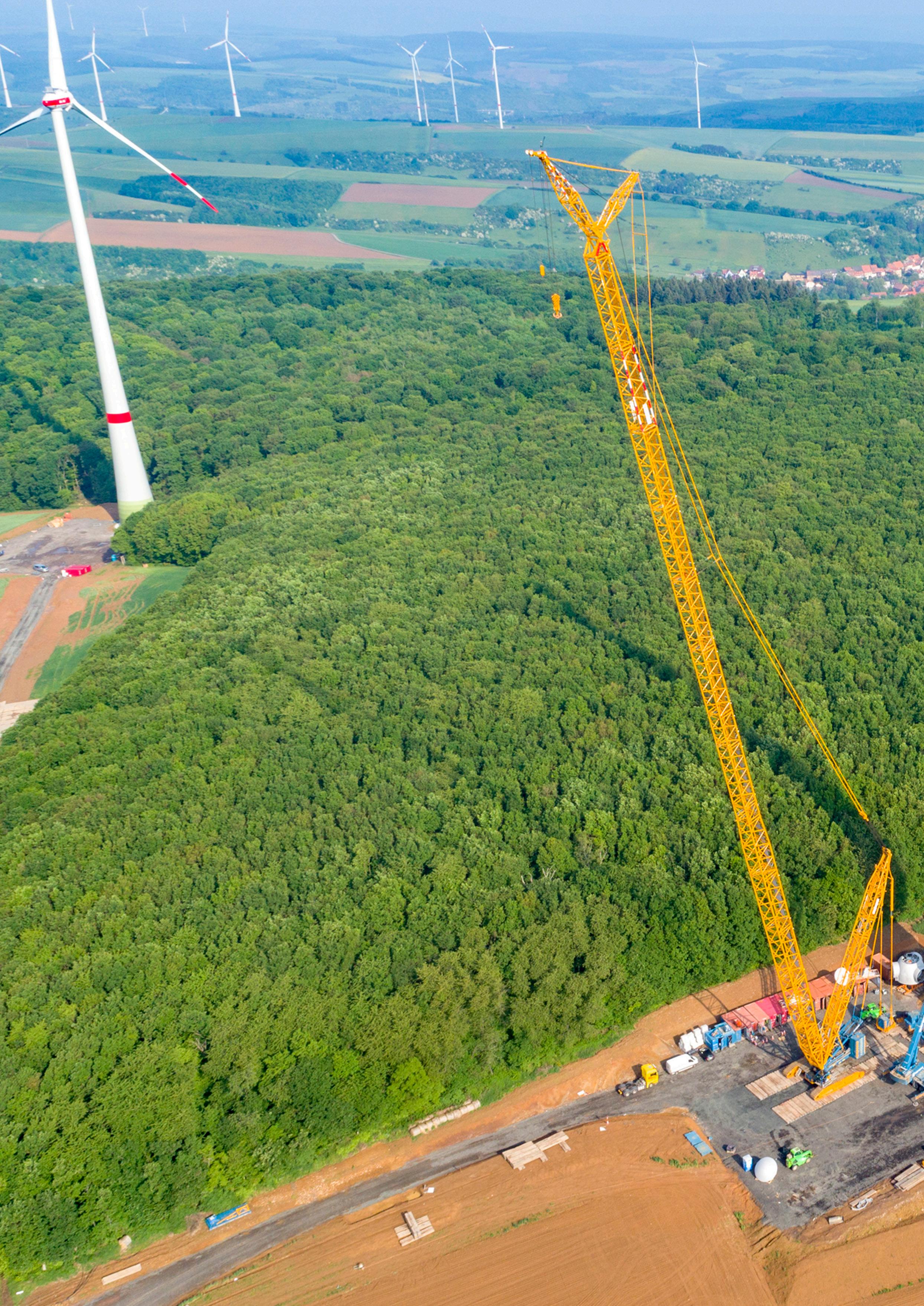
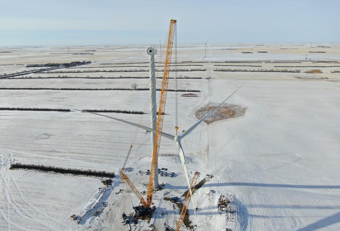
Kleopatra Kyrimi, Sarens, illustrates how preventive maintenance forms a crucial aspect of guaranteeing efficiency and reliability in the growing global onshore wind energy sector.
The global energy sector is currently experiencing one of the most exciting moments in its history. Technical and technological advances have led to a world where access to cleaner and more environmentally responsible energy is no longer aspirational but tangible and expanding rapidly – driven in large part by the ongoing growth of solar and wind energy, both onshore and offshore.
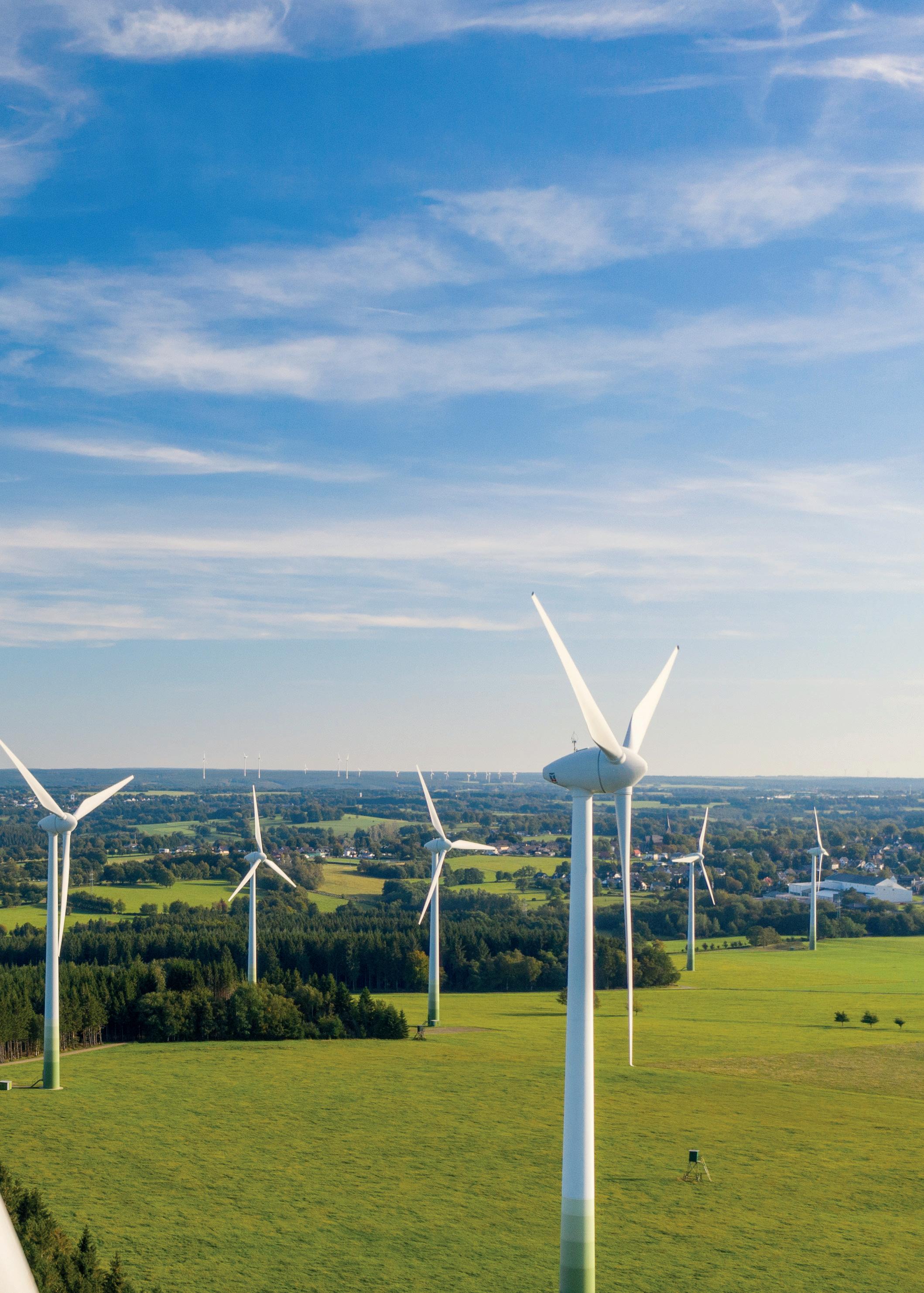
Figure 1 . PC 3800-1 crane working in Renkenberge wind farm, Germany.
The numbers are encouraging. In Europe alone, according to WindEurope, 13.8 GW of new onshore wind capacity was added in 2024, representing approximately 84% of the total new wind capacity installed across the continent. This equates to the installation of between 14 000 and 20 000 new onshore wind turbines in Europe, with Spain and Germany leading the way. Globally, the US and China continue to expand wind energy capacity alongside Europe.
This rapid growth is pushing the sector to adopt new techniques and technologies aimed at improving energy efficiency and shortening installation times while maintaining all safety measures. While the first turbines installed in the 1980s and 1990s barely reached 450 kW and stood around 40 m tall with 30-m blades, machines are being seen today that exceed 15 MW in capacity –enough to supply clean and renewable energy to more than 40 000 homes annually – with blades approaching 130 m in length.
This evolution has naturally increased the challenges for installation and transport. Each wind turbine component – whether the tower segments, nacelles, or blades – must be moved over hundreds of kilometres from the manufacturing site to often remote locations. As turbines grow in size, so does the need for heavier, taller lifting capacity and highly specialised logistics to safely and efficiently transport and assemble each part.
Preventive maintenance as a guarantee of an efficient energy sector
The pursuit of higher efficiency, which has led the industry to use increasingly larger turbines, has also brought about greater operational stress and wear. Fortunately, advancements in technology are helping ensure reliable performance – even in hard-to-reach locations or in extreme weather conditions, where each unit can be exposed to particularly extreme conditions of temperature, humidity, or wind.
Preventive maintenance has become essential in reducing downtime and improving overall performance as it is estimated that breakdowns and unscheduled downtime can result in an annual production loss of approximately 3% in an onshore wind farm. Digitisation is a great ally in this regard, not only for scheduling maintenance tasks, but also as a tool for detecting potential faults in advance. Increasingly, tools like predictive analytics powered by artificial intelligence (AI), are being used to address problems even before they occur as they are capable of detecting potential breakdowns or technical limitations that reduce the performance of a given unit in advance. Internet of things (IoT) sensors and digital twins are also playing a key role in helping operators optimise maintenance routines. According to consultancy, Infraspeak, predictive maintenance via process digitalisation could reduce operational costs in the wind sector by up to 20% during 2025. It is worth noting that preventive maintenance typically costs between €10 – €20 per kW installed per year, whereas major corrective repairs can exceed €100 000 in the event of a serious breakdown.
While maintenance intervals depend on variables such as turbine model and environmental conditions, standard checks on major systems like gearboxes, generators, and control systems usually occur every six months. Other activities, such as bearing lubrication, may be required as often as every three months in dusty or high-temperature environments. Blade inspections –aimed at identifying cracks or erosion – are increasingly performed using drones equipped with thermal imaging, LiDAR, or high-resolution cameras. Comprehensive maintenance overhauls are typically scheduled every 5 – 10 years, during which all components subject to wear and tear are thoroughly inspected, and any necessary repairs or replacements are made to the gearbox, rotor, or generator, so that the lifespan of each unit, estimated at approximately 20 years, can be extended. Although predictive maintenance significantly reduces downtime, failures still occur. Risk consultancies such as DNV estimate that a modern wind turbine can expect between 1 – 3 minor failures per year. These usually involve replacing components like blades or bearings, or addressing electrical system issues. While some tasks are completed at height, many require components to be dismantled and lowered for repairs on the ground.
Why a trusted heavy lifting partner is essential
This is where trusted heavy lifting specialists become vital. With turbines growing in both height and complexity, maintenance now demands the same level of expertise and equipment as installation. This has led companies such as Sarens
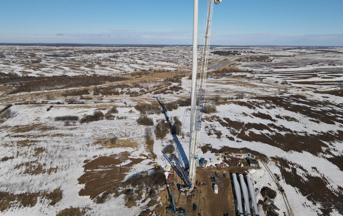
Figure 2 . Sarens installed one the highest wind turbines in Asmolovichi, Belarus.
The


The Perfect Partner for Your Hydrogen Project

NEUMAN & ESSER is the preferred provider for integrated hydrogen solutions. Get the entire technology as well as consulting, feasibility and implementation from a single source.
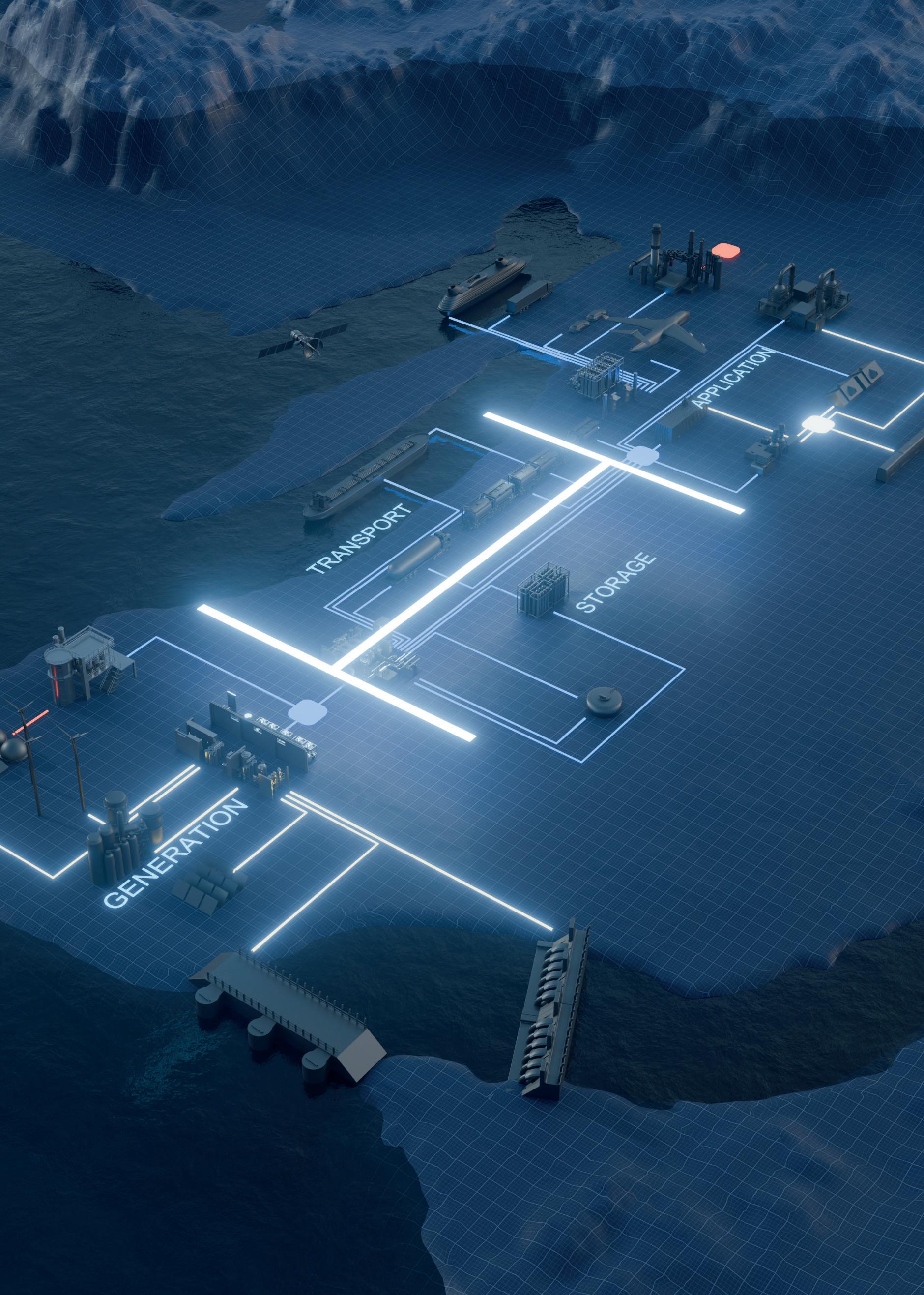
Hydrogen is essential for the energy transition, enabling decarbonization in industries, transport, and energy. Its value chain spans generation, storage, transport, and application. Green hydrogen, made with renewables, boosts sustainability, while investments in infrastructure drive innovation and economic growth.
Discover our interactive application and immerse yourself in the fascinating world of the hydrogen value chain.
www.h-of.energy

to frequently update its crane fleet with units. For example, the Liebherr LTM 1500-8.1, which has been used together with the Demag AC220-5 in maintenance work at the Longpark wind farm in Scotland, or the Demag CC6800-1 SH/LH+LF3 S3 with a capacity of 1250 t and a main boom of up to 107 m, which has been used at the Golden South wind farm in Saskatchewan, Canada.
Onshore wind farms located all around the world are often situated in remote or rugged environments with very limited space between turbines. For this reason, it is essential to work with a partner who can not only deliver the right equipment to the site, but also mobilise it efficiently and safely, ensuring minimal disruption to
the environment and surrounding infrastructure especially in spaces surrounded by turbines, where the space needed to manoeuvre is minimal. There is, however, another crucial consideration. As energy providers strive to lower their environmental impact, they increasingly expect the same commitment from their partners. At Sarens, this commitment is real and tangible, with the development of an emissions calculator – an industry first – which is offered during the request for quotation (RFQ) phase to help clients precisely understand their project’s carbon footprint. Unlike generic tools or greenwashing gimmicks, this calculator delivers practical insight to support meaningful green action, enabling clients to compare scenarios and select the most environmentally responsible option tailored to their project’s unique requirements.
Beyond consultancy, Sarens has also invested heavily in green technology. The entire SGC suite of cranes – including the SGC-90 ‘Little Celeste’ and the brand-new SGC-170, the second-largest in Sarens’ fleet – can be configured to operate electrically. In fact, the SGC-170 was designed from the ground up to be electric, reflecting its long-term commitment to clean innovation. These cranes not only operate with zero exhaust emissions but can also feed energy back into the grid, demonstrating that sustainability and world-class performance can go hand in hand. Sarens is also advancing the development of electric motors for its largest cranes and incorporating e-packs in its self-propelled modular transports (SPMTs), used quite often in the logistics of wind turbine components as part of a broader shift towards a low-emission future.
The way forward
As the wind sector continues to evolve and scale, the increasingly demanding development of wind infrastructure will be a key factor in achieving a safer and more sustainable future. However, for this to really happen it will be essential the industry does not let its guard down and continues to rely on the necessary preventive and corrective maintenance and inspection tasks. In this context, Sarens believes that the use of increasingly powerful yet environmentally-friendly machinery, together with innovative digital technologies that allow potential problems to be anticipated, will directly transform the way the energy sector operates in the coming years. Only by placing innovation, safety, and sustainability at the heart of every project can a wind energy sector that is ready to meet tomorrow’s challenges be delivered.
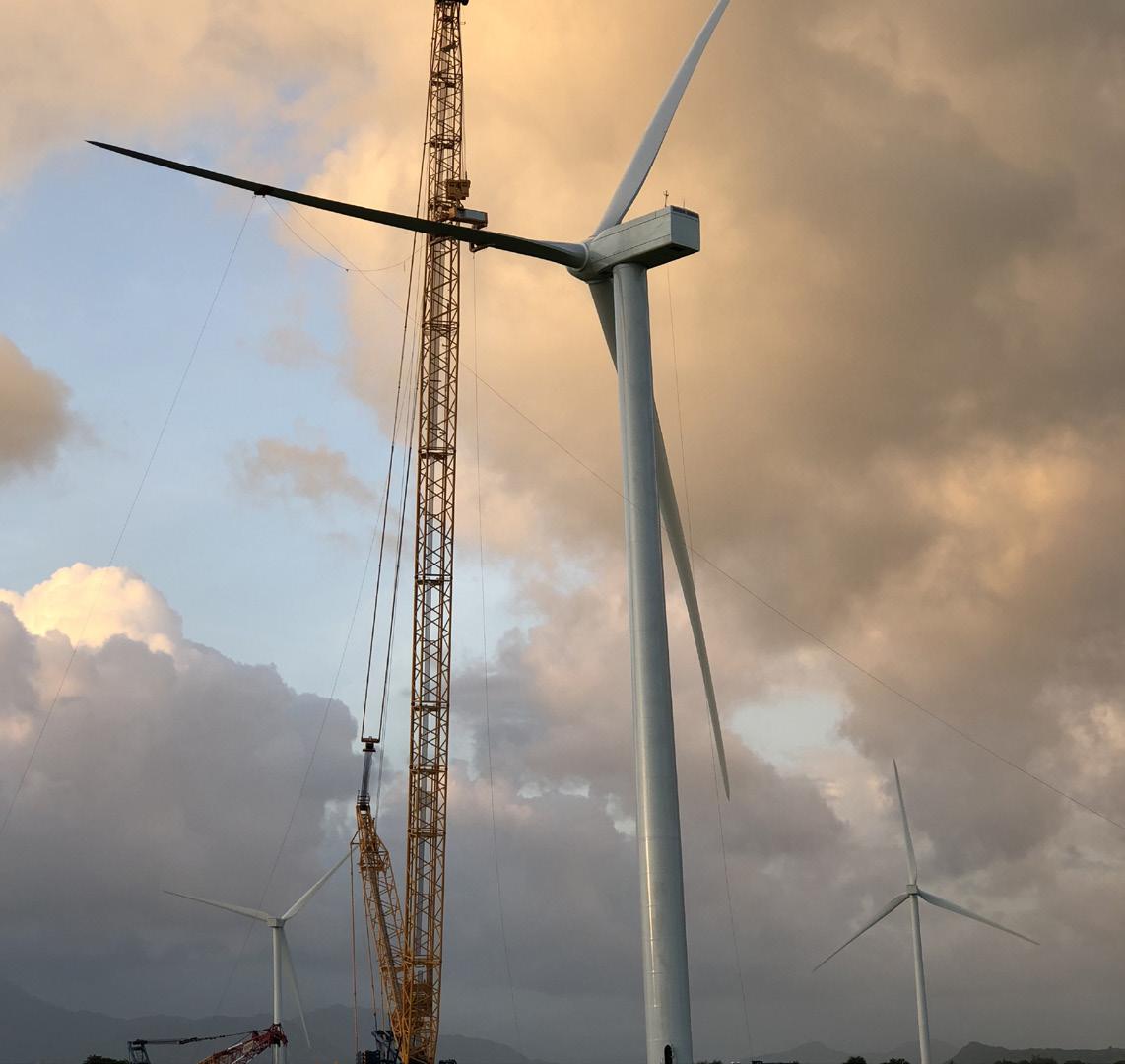
Figure 3 Sarens working in Assiniboia wind farm, Canada.
Figure 4 Sarens works in the Dam Nai wind farm in Vietnam.

Jens Wulff, CEO EMEA & India, NEUMAN & ESSER, Germany, outlines how an understanding of the whole hydrogen value chain can help reach the growing demand for high-purity hydrogen.
Decarbonising or de-fossilising the economy on the path to climate neutrality requires a transition to green technologies across the energy, industry, construction, and mobility sectors. Due to the volatility of electricity generation from renewable energies such as wind and solar power, reliable and cost-effective storage and transportation options for large amounts of energy are of key importance. Hydrogen plays a crucial role for these applications; it can be stored and transported and is a key driver for the decarbonisation of the economy, industry, and energy supply, which contributes to overcoming the climate crisis.
However, it is necessary to take a holistic view on the hydrogen value chain to ensure that technological

transformations are successfully implemented worldwide. Furthermore, an integrated and aligned view of the individual components of the value chain is important to ensure optimal results in terms of overall costs. Only with detailed knowledge of the individual processes from production to storage, transport, and distribution to the end-user, can the best solutions be achieved. As several components are working together in an integrated system, well-designed communication, control, and automation is of paramount importance. An own automation company which takes care of the process logic control of the individual components makes sure they are well aligned under one master automation roof. Additionally, the monitoring for asset management,
predictive maintenance and accelerated troubleshooting are integrated here too.
Production of hydrogen
The method and technology used for hydrogen production depend directly on the energy source of choice. Currently, methane converted into hydrogen by steam reforming (SMR)
is the most common source. This process produces around 10 t of carbon dioxide (CO2)/t of hydrogen, which corresponds to around 300 g/kWh. An alternative method is pyrolysis, in which methane is passed through molten tin in a bubble column reactor. This process produces elemental carbon as a by-product. By using certified biomethane, the CO2 footprint of these processes can be significantly reduced, enabling the production of ‘green’ hydrogen. However, direct CO2 emissions cannot be completely avoided.
Electrolysis produces hydrogen without direct CO2 emissions. There are various technologies that differ in terms of maturity and respective advantages and disadvantages. However, what all processes have in common is that water is split into hydrogen and oxygen molecules through an electrochemical reaction. The two most common methods are alkaline electrolysis (AEL) and proton exchange membrane electrolysis (PEM).
In PEM electrolysis, high-purity water is split using precious metal catalysts. The membrane used prevents the resulting gases from mixing. This ensures high gas purity at a discharge pressure of around 30 bar. In addition, PEM can effectively follow a volatile power profile, although the use of precious metal catalysts leads to higher costs.
In AEL electrolysis, an alkaline electrolyte is used, which reduces the required activity from the catalyst itself. A porous separator is used instead of a membrane, leading to higher cross-contamination. This contamination increases further during partial load operation, making it more challenging for AEL electrolysis to follow a volatile current profile. Additionally, entrained alkaline electrolyte can pass through the electrolyser and must be removed for subsequent processes. Here, the absence of precious metals results in lower investment costs.
Storage of hydrogen
Due to its low volumetric energy density, storing hydrogen under environmental conditions is not practical. The following basic methods are suitable for achieving sufficient energy density:
> Physical binding to a carrier material: This is done, for example, in solid metal hydride storage systems or in organic carrier liquids (LOHC).
> Liquefaction (LH2) by cooling below the boiling point (-252˚C): This achieves a density of approximately 70 g/l.
> Pressure storage at different pressure levels: Depending on the pressure level, mass, and load cycle requirements, different types of tanks are used – from simple steel tanks to composite tanks.
> Chemical bonding in ammonia or hydrocarbons: Depending on the chemical compound, various other storage options are possible.
All methods have limitations in terms of their application. What almost all storage methods have in common is that the hydrogen must be compressed by compressor systems for the storage process.
Transportation and distribution
There are several options for transporting hydrogen as a pure substance to end users or intermediate storage facilities.
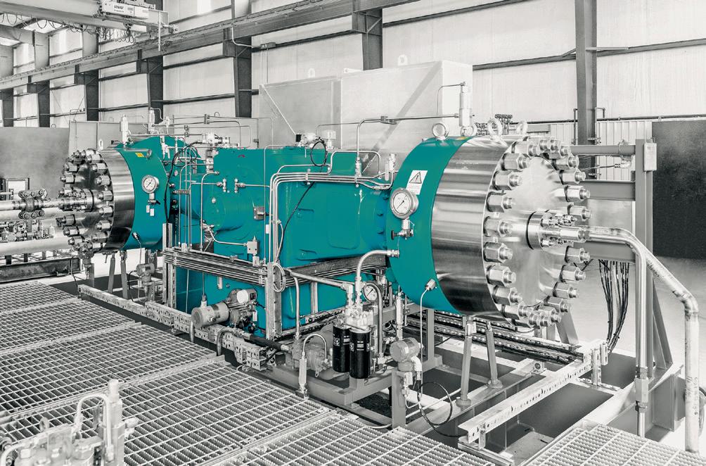
Figure 1 NEA|HOFER diaphragm compressor MKZ.
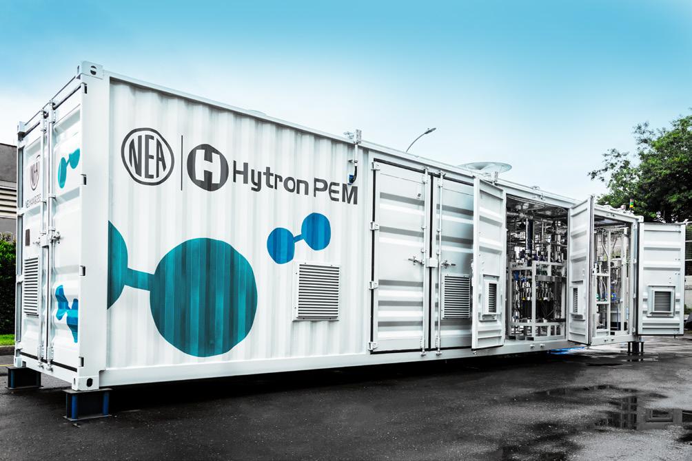
Figure 2 . NEA|HYTRON PEM electrolyser.
Figure 3 . NEUMAN & ESSER piston compressor 8-crank horizontal.
Depending on size and pressure level, quantities ranging from a few kilogrammes to around 1.5 t of hydrogen can be transported in mobile pressure storage units such as trailers or containers. A ‘rolling pipeline’, such as a freight train, can transport around 60 t of hydrogen, which equals approximately 2 GWh of energy. An LH2 trailer can hold about 3 – 4 t of hydrogen, and a large LH2 tanker with a volume of about 150 000 m³ of LH2 could deliver approximately 10 000 t of hydrogen. Pipelines can transport very large quantities of over 30 GW per pipeline.
End user
Hydrogen can be converted back into electrical energy or heat in various ways or used for material conversion. The conversion back into electricity takes place in fuel cells, e.g. for the mobility sector, or in gas turbines, for example as a reserve in the energy system. In processes with high heat and energy requirements (e.g. in the glass or paper industry), hydrogen can be converted directly into suitable burners. Hydrogen is also an important component for high-quality production in the chemical industry. In some areas, such as the steel industry, the functionalities can also be combined. There, hydrogen can be used to generate heat and serve as a reducing agent to produce raw iron from iron ore at the same time, for example. Depending on the application of hydrogen, there are different advantages and disadvantages as well as requirements that hydrogen must meet. When converted into fuel cells, approximately 50 – 60% of hydrogen’s lower caloric value is converted into electrical energy, while the remainder is converted into heat. In contrast to using hydrogen as a fuel in turbines or combustion engines, where an efficiency of around 30 – 40% is achieved at best, fuel cells require hydrogen of the highest purity.
The importance of the right compressor technology
When looking at the individual processes and components of the hydrogen value chain, it becomes obvious that optimal solutions can only be found if there is extensive expertise in the individual steps. Furthermore, hydrogen can only be used if it is compressed. However, the selection of the appropriate compressor technology must always be made in co-ordination with the following steps along the hydrogen value chain. Since hydrogen has a very low molecular weight, compressors based on the displacement principle are the method of choice. These achieve isothermal efficiencies of up to more than 80%. If high-purity hydrogen is required, water-filled screw compressors or dry-running piston and diaphragm compressors are suitable. Water-filled screw compressors achieve final pressures of 15 bar, dry-running crosshead piston compressors over 300 bar, and diaphragm compressors and hydraulically-driven piston compressors well over 1000 bar. For corresponding flow rates, the diaphragm compressor and the hydraulically-driven piston compressor require higher suction pressures. The diaphragm compressor can compress around 1000 Nm3/h from 30 bar to 1000 bar in three stages. In contrast, a large-volume piston compressor with a drive power of 22 MW can compress more than 800 000 Nm3/h from 40 bar to 80 bar. This means that
the output of 4 GW of electrolysis can be transported with a single large compressor. If purity is not such an important factor, oil-lubricated screw compressors can also be used for pressures of up to 50 bar, or piston compressors with cylinder lubrication for final pressures of up to 1000 bar.
It depends on the required pressure
Trailers supplied to refuelling stations typically operate at pressures between 300 – 500 bar. In terms of hydrogen volume, a trailer with 300-bar steel containers can transport around 500 kg of hydrogen, although these are often limited in the number of charging cycles. A 40-ft MEGC gas container with a pressure of 380 bar, on the other hand, can transport around 1000 kg of usable hydrogen and has a significantly longer service life, but at a higher initial cost.
Depending on the type of electrolyser, its typical discharge pressures range from a few millibars to around 30 bar. Consider briefly a system with atmospheric discharge pressure to a system with 30 bar discharge pressure. The filling pressure of the trailer should be 500 bar. With atmospheric suction pressure, pre-compression is necessary due to the low displacement volume of the diaphragm compressor. Four compressor stages are required to achieve a pressure of more than 30 bar. At 30 bar suction pressure, the diaphragm compressor can compress to over 500 bar in two stages. The supposed cost and efficiency advantage of an electrolyser with atmospheric discharge pressure is therefore offset by the four additional compressor stages and the additional use of another compressor. The efficiency of mechanical compression in the piston compressor and that of electrochemical compression in the pressurised electrolyser are almost identical.
The choice of discharge pressure and type of electrolysis also influences the choice of gas drying and oxygen removal. Thus, the selected electrolyser pressure and energy supply have a major influence on the choice, dimensioning, and complexity of the compressor and gas treatment system.
It is therefore crucial to have a good understanding of the properties and limitations of the various components in the hydrogen value chain. The seemingly obvious cost advantages of investing in a low-pressure electrolyser can be negated or eliminated by the higher operating costs of a complex compressor system. Here, providers of integrated solutions, including aftermarket services, can identify and offer the most efficient solution.
Outlook
The demand for high-purity hydrogen will increase sharply with the increasing conversion of mobility, especially in the heavy transportation sector, e.g. truck, bus, and train sectors. This means that compressors for both filling trailers and hydrogen refuelling station will have to cope with larger high-purity flow rates at pressures in the region of 500 bar in the future. For this reason, the development of dry-running piston compressors that can achieve flow rates of over 1000 kg/h at this pressure level must be driven forward. Those who master compression and understand the process environment can drive forward the energy transition and deliver significant added value for the customer.
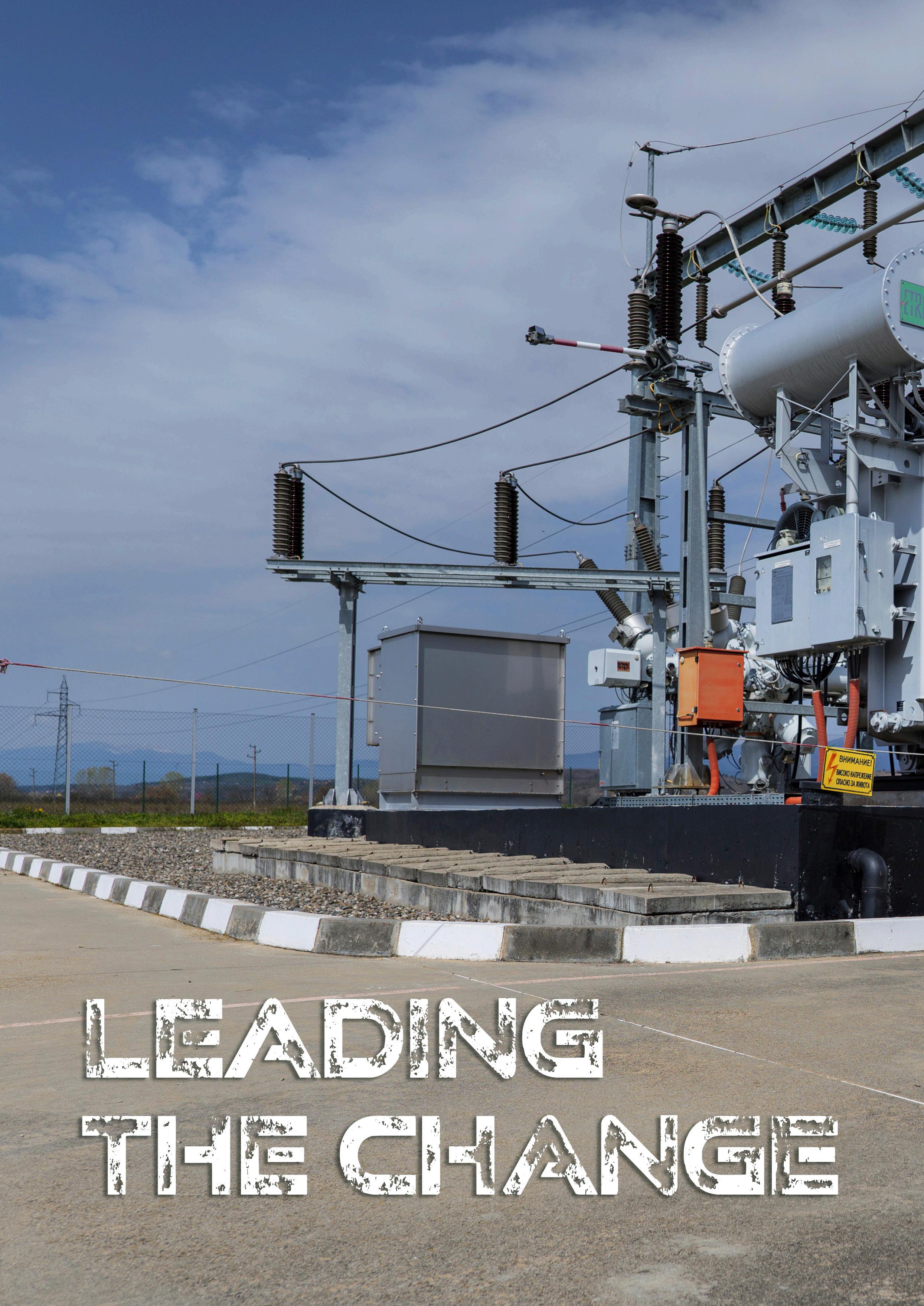
Figure 1 . Lifecycle services are becoming more critical than ever, as modernising the existing installed base is equally essential as building new infrastructure. Hitachi Energy’s transformer service portfolio has proven to be effective in delivering real value across diverse markets.
In a conversation with Energy Global, Bruno Melles, Managing Director of Business Unit Transformers at Hitachi Energy, explores how transformer technology is shaping a more resilient, efficient, and sustainable energy system.
As the global energy transition accelerates, power systems are facing unprecedented pressure.
The rapid shift to cleaner energy sources, the electrification of traditionally carbon-intensive sectors, and the urgent need to modernise ageing grid infrastructure are redefining the requirements for performance, resilience, and sustainability. By 2040, over 80 million km of grid infrastructure will need upgrades.1
An essential part of grid infrastructure is power transformers. The critical components for reliable, efficient, and scalable power delivery are vital in ensuring that the grid can meet today’s challenges while preparing for the future.
Amid the increasing demand, utilities face another significant challenge: managing an ageing fleet of power transformers. They operate under different conditions that no longer match their initial design specifications. Replacing these assets is expensive, time-consuming, and logistically complex. In response, utilities and grid operators are adopting transformer lifecycle management strategies to improve the performance and reliability of their existing transformers. This approach bridges the gap between operational excellence and long-term sustainability objectives.
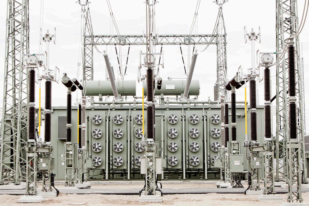
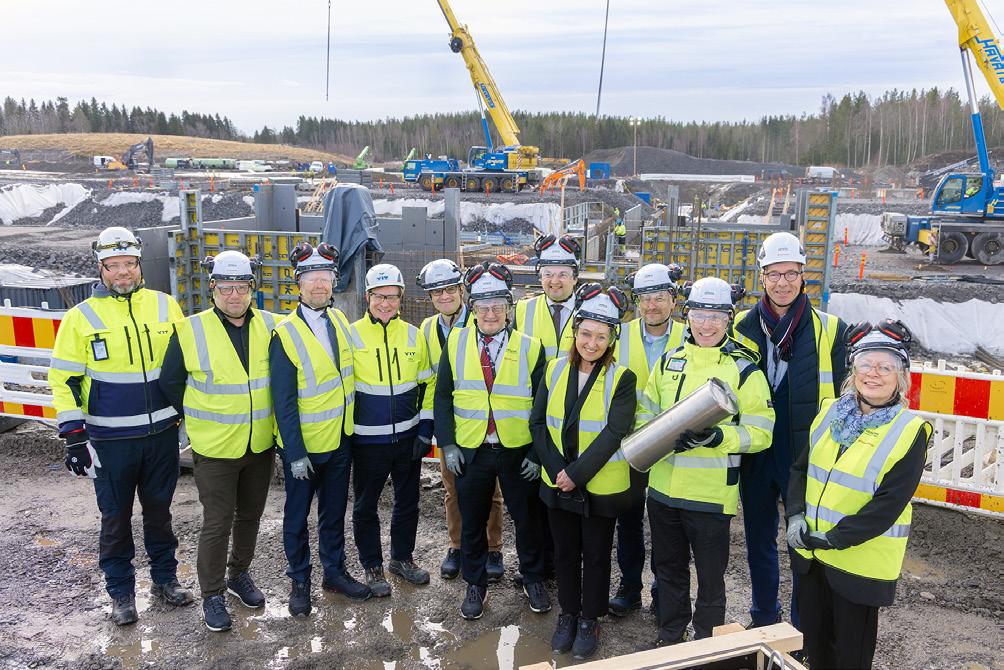
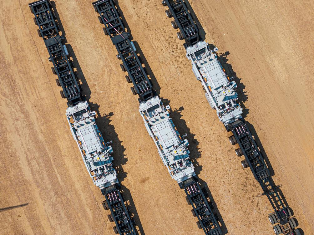
Figure 4 In the US, Hitachi Energy custom-engineered a mobile transformer solution, as well as turnkey services for Avangrid, a leader in renewable energy and part of the Iberdrola Group. These innovations ensured swift, reliable, renewable energy transmission even during extreme weather events or supply chain disruptions.
To gather deeper insights on how Hitachi Energy is addressing these challenges, Energy Global (EG) sat down with Bruno Melles (BM) for a one-on-one discussion on the company’s approach to advancing transformer technology and driving innovation in transformer solutions.
Looking towards the global power system of 2050, it is anticipated the world will needing approximately four times the current power generation capacity, and transferring up to three times as much electrical energy compared to 2020. Electricity will become the backbone of the entire energy system. Consequently, the demand for transformers is expected to rise significantly across all applications in the coming years. This growth will vary depending on markets and applications, with annual growth rates estimated to range from 1 – 2% globally to 5 – 10% in fast-growing markets and segments such as renewables and data centres.
Hitachi Energy is at the forefront of this transformation, driving innovation through an integrated strategy that anticipates future demands and accelerates the shift towards a decarbonised future. A key component of the company’s strategy is the expansion of its global manufacturing capacity and the strengthening of supply chains – both critical to ensuring the timely delivery of transformer solutions.
The strategy is deeply rooted in innovation and sustainability. The company is developing eco-efficient transformer designs, integrating digitalisation, and providing end-to-end transformer lifecycle support. By leveraging new technologies and ensuring operational excellence, Hitachi Energy is not only addressing today’s grid challenges but also future-proofing grid infrastructure.
As the world’s largest transformer manufacturer, Hitachi Energy is working closely with customers, suppliers, and other industry stakeholders to address the increased demand for transformers. It is focusing on understanding the market needs across geographies, segments, and applications, and translating that into market demand. In addition, it is closely collaborating with its customers to understand their long-term needs for transformers.
To meet the market demand effectively, Hitachi Energy is leveraging its global transformer footprint, which includes 60 transformer factories and 30 service centres worldwide. The company is investing in its existing factories to increase capacity through productivity enhancements, investments in new machinery and personnel, expansions, and eventually, new factories, product lines, and expanding the service organisation’s footprint and offering. In fact, the company has committed to a US$1.5 billion investment until 2027 to significantly grow capacity.
Throughout its full value chain, the company is securing the availability of necessary materials by maintaining a high level of vertical integration in its transformer manufacturing process. Hitachi Energy’s global footprint allows it to leverage its strategic supplier base to serve multiple markets across geographies.
To specifically address customers’ needs, the company is working together on long-term planning and discussing the best ways to fulfil their transformer needs, including potential investments and co-operation if economically viable for all parties. Additionally, it is investing in its people, expanding its workforce, and ensuring they are trained and properly qualified. This investment in people is essential to keep pace with innovation and the growing demand.
Figure 2 To meet market demand effectively, Hitachi Energy, the world’s largest transformer manufacturer, leverages its global transformer footprint, which includes 60 transformer factories and 30 service centres worldwide.
Figure 3 . In June 2024, the foundation stone for the new Hitachi Energy Park was laid in the Vaasa region in Finland. Expected to be operational in 2027, it will feature a transformer factory that will double the company’s production and testing capacity of transformers in Finland.


In summary, the approach is centred around people, long-term partnerships, and building the right dimensions and capabilities to address the increased demand while leveraging global footprint. Hitachi Energy has record investments underway to expand its capacity and build new factories. To put that in context, all the company’s 60 manufacturing facilities globally are impacted by the announced US$1.5 billion investment in the transformer business.
EG: Why is it important to raise awareness for lifecycle management? What benefit does it bring to customers?
BM: As the energy transition accelerates, lifecycle services are becoming more critical than ever. Modernising the existing installed base is just as essential as building new infrastructure.
Lifecycle management enables a shift from reactive maintenance to a more predictive, data-driven approach, empowering utilities and grid operators to maximise asset reliability, reduce operational risk, and optimise the total cost of ownership. For transformers, this transition is especially critical in sectors such as rail transport, where transformer failures can result in
from reactive maintenance to a more predictive, data-driven approach, empowering utilities and grid operators to maximise asset reliability, reduce operational risk, and optimise the total cost of ownership.
significant service disruptions and financial losses. By embedding lifecycle management into asset strategies, customers gain not only operational resilience but also long-term sustainability and capital efficiency.
At Hitachi Energy, we recently strengthened and will further invest in our service portfolio and capabilities powered by digital technologies by establishing a dedicated Service Business Unit. For example, our robust portfolio of services, including our digitally enabled service through TXpertTM Ecosystem, provides real-time monitoring and data-driven insights. These tools significantly reduce unplanned outages and the total cost of ownership.
Ultimately, lifecycle management is about maximising asset value while aligning with broader operational and sustainability goals. It ensures that transformers continue to perform reliably, safely, and efficiently throughout their intended lifespan –and beyond.
EG: How has Hitachi Energy’s transformer service portfolio helped customers achieve significant business or operational outcomes?
BM: We’ve seen first-hand how our service portfolio delivers real value across diverse markets. In El Salvador, for example, our collaboration with DELSUR focused on modernising their distribution infrastructure. By deploying our eco-efficient EconiQ® transformers alongside the TXpert digital ecosystem, we helped them significantly enhance grid reliability, reduce environmental impact, and make smarter, data-driven decisions.
In the US, we supported Avangrid with a mobile transformer solution and turnkey services – an approach that proved critical in ensuring swift, reliable, renewable energy transmission, even amid extreme weather events and supply chain disruptions.
In Asia, our work with the Provincial Electricity Authority in Thailand enabled the extension of over 250 ageing transformers through targeted refurbishment and condition assessments. This avoided costly replacements and supported a more circular, sustainable energy model. Similarly, in Macau, China, we partnered with CEM to apply our Lumada APM diagnostics, helping them identify high-risk units and maintain grid stability in the face of rising demand.
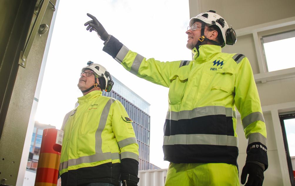
We’ve also seen excellent results in Europe, where our partnership with Helen in Finland showed how legacy infrastructure can be repurposed for a low-carbon future. By refurbishing two 1970s-era transformers for use in a new electric boiler plant, Helen is on track to cut 440 000 t of carbon emissions over five years, directly contributing to Finland’s carbon-neutrality goals.
Collectively, these partnerships demonstrate how our service portfolio empowers utilities to optimise asset performance, enhance resilience, and accelerate the energy transition.
EG: How does your transformer service portfolio reflect Hitachi Energy’s global leadership?
BM: Our transformer service portfolio is shaped by decades of experience, global reach, and a clear understanding of what our customers need to keep their operations reliable and efficient. We take pride in our ability to apply the right expertise, tools, and technologies to support their needs.
Figure 5 Hitachi Energy’s partnership with Helen in Finland entailed the refurbishment of two 1970s-era transformers for use in a new electric boiler plant. With this, Helen is on track to reduce carbon emissions over five years, directly contributing to Finland’s carbon-neutrality goals.
Figure 6 The establishment of a dedicated Service Business Unit for transformers gives Hitachi Energy a competitive edge. Powered by digital technologies, its service portfolio for lifecycle management enables a shift
We focus on practical outcomes, such as reducing unplanned outages through condition-based maintenance and diagnostics, improving asset performance with real-time monitoring, and supporting long-term planning with data-driven insights. Our service agreements, such as EnCompassTM, are structured to be flexible –enabling them to support both technical and financial goals, whether that involves extending asset life or managing operational risk.
It is also important to note that we have designed our service models to be adaptable. We can support transformers of any brand or age across a wide range of industries. We follow global standards while adapting to local needs, ensuring consistent quality every time.
EG: As the world’s largest manufacturer of transformers, how does Hitachi Energy see its role in shaping the grid of the future?
BM: We see Hitachi Energy as a key driver of the energy transition, and this is demonstrated by the scale of our manufacturing capabilities, continuous innovation, deep technological expertise, and expansive global footprint. We recognise the need to accelerate the delivery of transformers and key components to enable the industry to expand more rapidly and advance critical infrastructure projects.
It is also important to note that our focus goes beyond building new infrastructure. We are equally committed to strengthening and extending the life of existing assets. Hitachi Energy is the world’s largest manufacturer of transformers, and we see it as our responsibility to lead on both fronts: expanding capacity to meet growing demand while also enabling a more resilient and sustainable energy system.

5 - 6 November 2025
In 2024, we announced a major investment of over US$1.5 billion to significantly expand our global transformer manufacturing capacity by 2027. This investment builds on a previously announced US$3 billion commitment and includes the development of new facilities across Europe, the Americas, and Asia. In addition, we invested around US$180 million in a new state-of-the-art transformer factory in Finland’s Vaasa region, reflecting Hitachi Energy’s commitment to innovation, quality, and sustainability.
Recently, we committed to investing over US$250 million through 2027 as a strategic response to the global transformer shortage.
A significant portion of this funding is dedicated to expanding manufacturing capacity in the US, with a particular focus on Virginia, Missouri, and Mississippi. These facilities will increase the production of critical components, such as bushings and insulation, which are essential not only for our own systems but also for supporting the broader industry.
These investments are for building supply chain resilience, reducing lead times, and creating skilled jobs in the communities where we operate. At the same time, we’re investing heavily in our people, digitalisation, engineering, and R&D to extend the life of existing transformer fleets. By applying advanced monitoring, diagnostics, and service models, we help utilities and industries maximise the value of their assets – reducing the need for premature replacements and minimising environmental impact.
References
1. ‘Electricity Grids and Secure Energy Transitions: Executive Summary’, International Energy Agency, www.iea.org/reports/electricity-grids-and-secureenergy-transitions/executive-summary


As the offshore wind sector develops, Sarah McLean, Lead Content Manager, and Drashya Goel, Senior Client Success Manager, Spinergie, delve into how digital reporting forms a crucial next step in tackling emissions at each stage of the wind farm lifecycle.
Every stage of the wind farm lifecycle comes with a measurable environmental cost. As the market sees longer supply chain transits and bigger infrastructure and project sizes, greenhouse gas emissions across all operations face increased scrutiny.
Until recently, emissions reduction in offshore wind has been mostly reactive and driven by regulatory compliance and client demands rather than strategy. Charterers are

including lower emissions in tender requirements and expressing a growing preference for upgraded, efficient vessels while vessel owners are pushing their own net-zero requirements in line with local regulations. In response, wind developers have turned to using digital solutions to reduce their operating emissions.
Yet without industry-wide cohesion there is a risk of data silos and players being left with an abundance of data but little insight into how best to use it to improve

their operations. Real emissions reduction requires a sector-wide operational transformation and digital tools are a catalyst for the shift from reactive to proactive.
Equipped with standardised data streams, vessel owners, managers, and charterers gain:
> Access to immediate, actionable insights into activities on a vessel, project, or company-wide basis.
> Benchmarking capabilities, helping set and measure performance baselines.
> Contextual analytics (weather, wave, vessel behaviours, etc.), to inform decision-making and reduce the risk of dispute.
Digitalisation in offshore wind offers multiple benefits to individual players, yet without a broader market adoption, the entire sector risks falling behind. This article
presents the benefits of digital integration across the various lifecycle phases of an offshore wind farm.
A shift is underway: Digital reporting in the offshore wind sector
The traditional approach to reporting does not fit modern operations. Crews waste their time struggling with multiple, disconnected spreadsheets. Strategy teams are forced to operate with limited or incorrect data which makes it nearly impossible to gain meaningful insights. Meanwhile, onshore teams are faced with having to use multiple data sources just to understand fleet status and to check in on operations – not ideal when quick action is required.
Digitalisation addresses these inefficiencies by consolidating fragmented data and disparate reporting sources into a centralised, accessible system. Currently, the sector has shown varying levels of adoption from low-to-no digitalisation, to those with full adoption of these solutions.
Those who are fully embracing the shift to digital find themselves with an operational and competitive advantage.
With real-time fuel consumption analysis alongside metrics such as vessel speed, digital tools are geared towards addressing the inefficiencies that drive higher fuel consumption and emissions. With automated data coming from sources such as AIS tracking and onboard sensors, it becomes more easily verifiable. Easy verification is something that is becoming increasingly important amid global and regional emissions regulations from the EU Monitoring, Reporting, and Verification (EU-MRV) regulation to the International Maritime Organization (IMO) Data Collection System (DCS) Carbon Intensity (CII) reporting. These increased regulatory requirements are a key driver in the move from traditional systems to digital. The relative speed of the transition to tighter emissions regulations means that there is a high risk of gaps in implementation alongside the potential to turn reporting into a bigger burden than it needs to be.
This means that digital reporting is no longer an abstract concept for the future, it is happening now, and those who take only a passive interest risk being left behind.
Digital reporting across a wind farm lifecycle
For clarity, the wind farm lifecycle has been split into three distinct phases: pre-construction, construction, and post-construction.
Lessons learned in pre-construction and beyond can inform future planning
Digital tools can play an important role long before work on a new project even begins. Sustainability-focused non-priced criteria (NPC), specifically environmental evaluation, is becoming a leading decisive factor in offshore wind auctions. Governments, especially in Europe, have increased the number of carbon footprint criteria
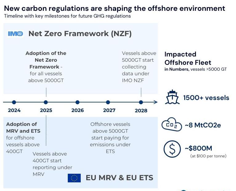
Figure 1 . >10% of the offshore fleet impacted by IMO Net Zero Framework.
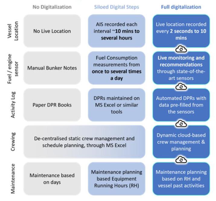
Figure 2 Journey to digitalisation.


included in their auction processes. From this, developers are tasked with providing comprehensive plans and strategies to ensure a lower footprint can be achieved.
How can this be demonstrated with accuracy? Well, the data generated, and lessons gathered, from one project will go a long way to informing the strategy of another. If a comprehensive dataset has been obtained from a project of similar scope (seabed conditions, water depths, marine spread etc.), then a developer already has a solid foundation to build their case.
However, without understanding what the main emissions drivers have been in previous projects, it is close to impossible to respond to these auction criteria with any real accuracy. Digital reporting provides standardised data regardless of fleet diversity and offers a continuous feedback loop. With ongoing operational feedback, it is possible to adjust and optimise over time. The improvements generated during this process are most valuable for informing future projects.
With access to real-time recorded data on vessel activity and fuel consumption, market players are moving away from broad assumptions based on limited data sets to evidence-based impact assessments.
Case study: Digital reporting for the survey phase
Digital reporting begins the real work as soon as any vessels are involved – right from the very first survey.
Multiple vessel types, from small scouting vessels to large geotechnical vessels, are required during the survey phase of an offshore wind farm. The scope of this phase is vast as these vessels are used to undertake comprehensive investigations of the seabed, subsoil, and marine environment of the site. Thousands of kilometres will be thoroughly assessed and all of the vessel and operational data must be recorded and assessed.
Previously, survey teams often used vast, complex spreadsheets to track survey activities. However, this method has a number of drawbacks: it is time consuming –for some team members a significant portion of their days is spent solely on reporting; mistakes are easy to make and difficult to correct – often they will cascade through spreadsheets before being found resulting in complicated rework; and finally, while the data was recorded, teams had no way of easily obtaining insights from it. Traditional ‘spreadsheet methods’ are no longer fit for purpose as project sizes increase.
Digital reporting solves each of these issues by providing a centralised source for all vessel data regardless of manager. The developer can see which vessels are operating as expected and which may be lagging behind what was contractually agreed. Data is more accurate and should be blocked from cascading through the system with in-built quality checks. Finally, operational insights are not only more easily identified, but are also significantly easier to share among the team to keep everyone aligned. This saves significant amounts of time both on data compilation and on data analysis.
Avoiding incidents and staying on track during the construction phase
Traditionally, onshore staff have had limited remote monitoring capabilities during the construction phase of a wind farm project. They often had to rely on basic AIS data and voice communication. But with digital tools, data is centralised and accessible to all teams alongside real-time remote monitoring. When alert systems are activated, teams have an additional layer of power and can react immediately to issues such as speed breaches in order to make significant fuel and emissions savings over time.
The historical data captured in such a solution also provides context for any incidents. For example, say a smaller vessel such as a crew transfer vessel (CTV) has had a collision with a wind turbine installation vessel (WTIV), the developer may suspect reckless behaviour on the part of the CTV. Yet, with contextually enriched digital data, the CTV manager will be able to provide proof that the vessel was not speeding, and that there had been unusual and unpredictable wave patterns at the time of the collision. This objective evidence would save a significant amount of time on the part of both parties as they sought to resolve the issue.
Beyond fleet monitoring, digitalisation opens up significant possibilities for project management. The installation phase of an offshore wind project is complicated. Most commercial projects will have a wide marine spread undertaking multiple journeys from marshalling ports to the wind farm site for hundreds of components.
With offshore wind being a growing sector, and many regions yet to enter maturity, any learnings are essential to helping inform future projects. This could look like knowing which vessels are underperforming, and why, or understanding the context behind why one component
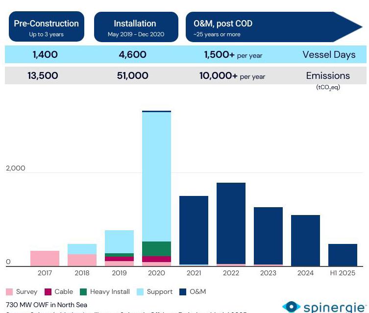
Figure 3 Construction of an onshore wind farm can take 6000+ vessel days. Source: Spinergie Market Intelligence, Spinergie Offshore Emissions Model 2025.
took significantly longer than another to install at the same project.
Equipped with this information, wind developers have a significant data bank that will not only inform their future NPC evaluations, but also save time and money on their ongoing operations.
Optimising vessel activity during operations and maintenance
After commissioning, a wind farm enters the operations and maintenance (O&M) phase which focuses on ensuring optimum availability and functionality. During this phase, technicians undertake regular visits to each turbine and foundation for preventative and reactive maintenance. This can be complex to track, especially for those developers who may be managing multiple wind farms across different time zones and regulatory environments. With multiple wind farms comes multiple vessel or equipment designs, which creates a significant problem when it comes to standardisation. Digital reporting helps bridge this gap.
Effective digitalisation during this phase allows charterers multiple optimisation opportunities. They can monitor vessel availability for contractual periods to optimise fleet scheduling, and reduce the impact of weather on operations by proactively planning around inclement weather events. This is all while standardising the data regardless of region or operation to create beneficial learnings.
Once again, previous learnings play an important role in the benefits of digital reporting during O&M as it will unlock insights into fleet and crew optimisation based on previous periods. Digital solutions unlock where crews or vessels have been over or under-utilised and allow for the adjustment of future behaviours to optimise operations, costs, and emissions.
Conclusions
The transition from traditional reporting methods to integrated digital solutions is reflective of the evolving nature of the offshore wind sector. As offshore wind develops, there are an increasing number of projects managed by each developer, who also has to contend with larger and more diverse fleets. This increases the amount of data to collect and process so fragmented reporting and sporadic data collection no longer fits.
Industry players, especially developers and vessel managers, need more efficient operations. Crews need to spend less time on reporting tasks, and onshore teams need granular data that they can rely on to strategise.
As emissions regulations intensify, the widespread adoption of digital integration will be essential for avoiding the steep penalties that lie in wait for non-compliance. Furthermore, it is the only way to ensure that data is accurate and insightful enough to facilitate maximum efficiency and minimal environmental impact through each phase.

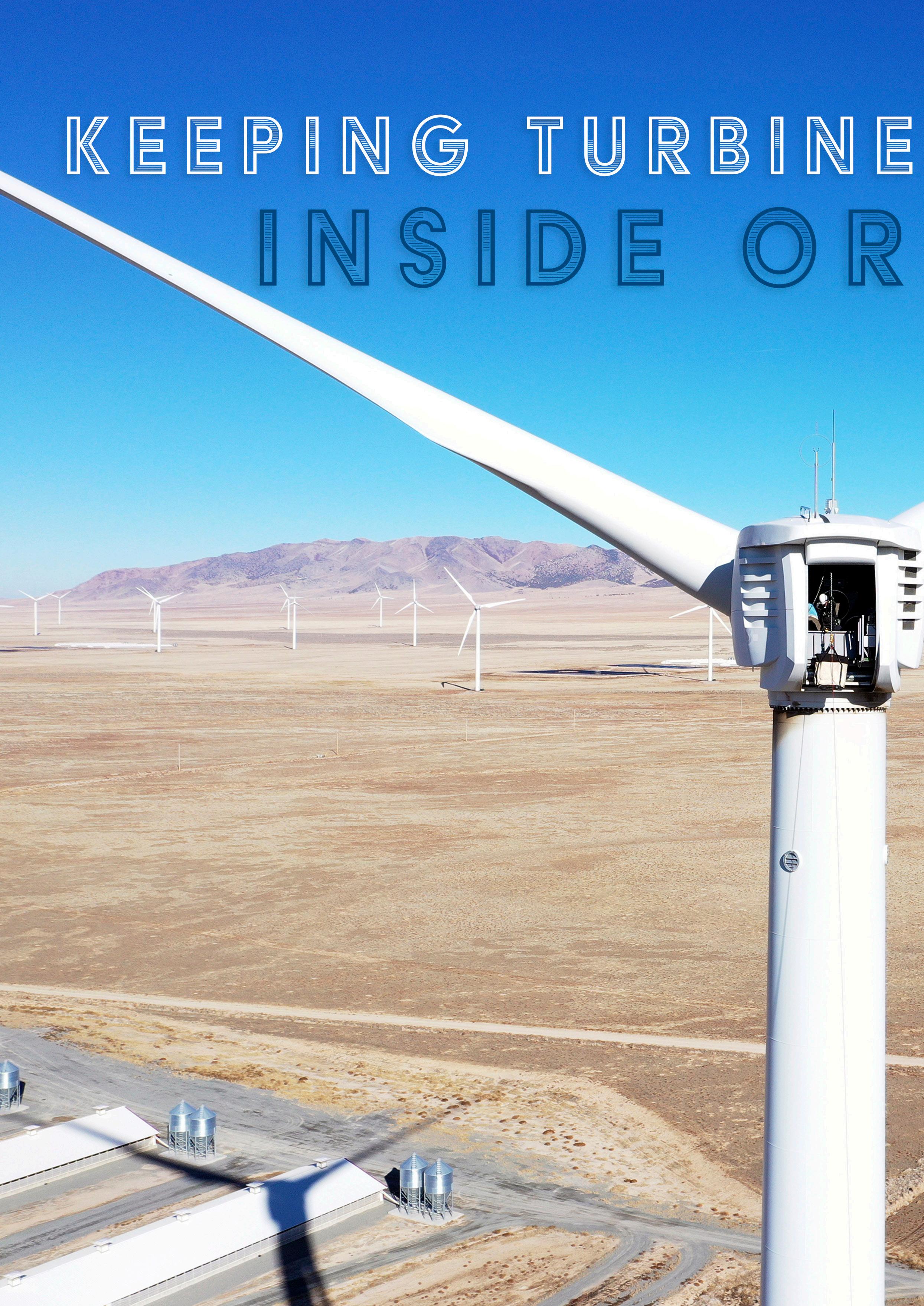
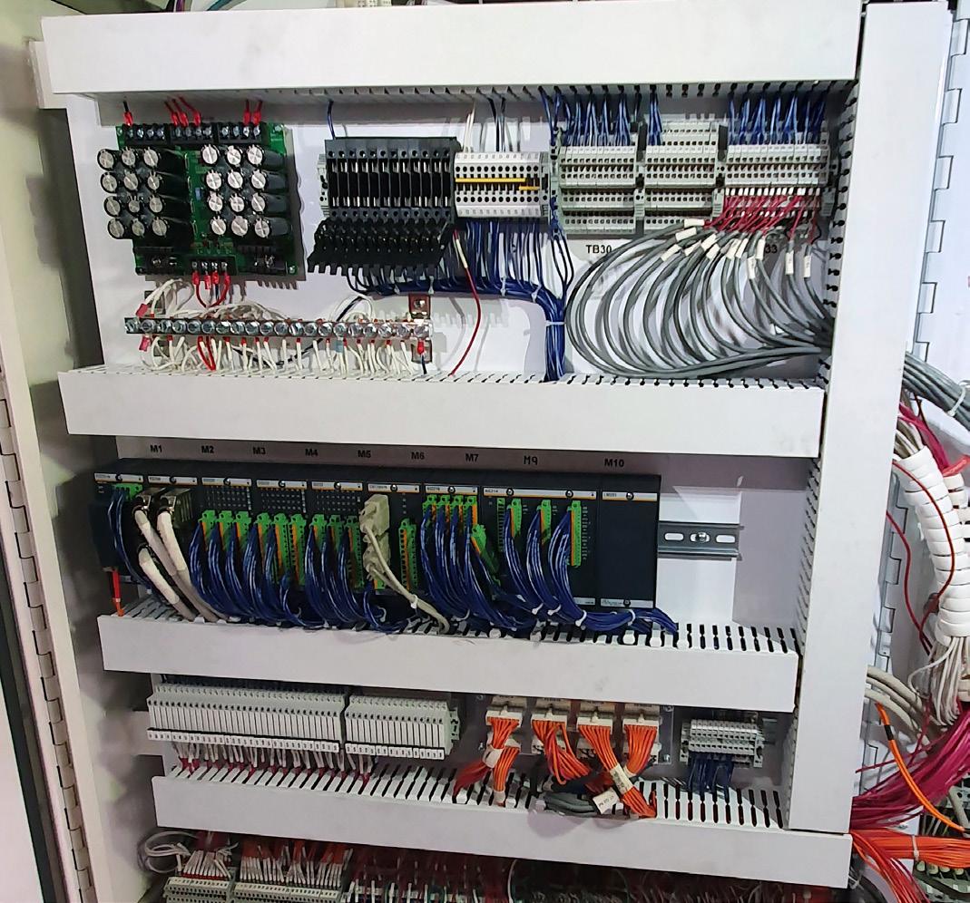
Figure 1 . 165 wind turbines with a total output of 306 MW are part of the Milford wind farm in Utah. After around 15 years of operation, operator Longroad commissioned Bachmann electronic to provide a complete solution that would enable safe and productive continued operation.
The profitability of wind turbines is determined by productivity and availability. Condition monitoring supports maintenance decisions, identifies potential cost savings, and avoids unforeseen failures. David Futter, Condition Monitoring Consultancy at Bachmann Monitoring GmbH, and Frank Fladerer, Bachmann electronic GmbH, compare the advantages and challenges of doing this in house or through an external partner.
Doing it in house vs employing a third party.
Decision-makers are always faced with this question when a new task lies outside the core competence of an organisation. There is rarely a single answer to this question, as the perfect solution is all too often dependent on many factors. This is also the case with condition monitoring.
Challenging task
Monitoring the condition of wind turbines is a complex art. A wide variety of sensors are installed at selected points on the drive train, rotor blades, and tower. These sensors deliver a continuous stream of raw data. Without appropriate processing, the data is worthless. Only after processing is it possible to visualise and

interpret the numerous possible effects of small changes over time on certain sensor readings, and to assess the potential consequences.
In addition, condition monitoring analysts are working with increasingly complex calculation methods to predict the impact of a small change in measurement data on the wind turbine. These algorithms are trained and continuously checked using years of data from many different wind turbine types.
Complex interaction
In addition to the hardware and software for monitoring, and a suitable visualisation tool, specialist knowledge is also required; above all, this includes expertise in vibration analysis. However, such expertise requires not only advanced training, but also experience working with a large number of turbines over a long period of time to understand the actual meaning and significance of changes in the data. Furthermore, if analysts are familiar with the type of turbine being monitored, they will deliver more precise information about the most likely failure mechanisms. At the same time, prior experience helps to assess whether and, if so, which remedial measures can be implemented, either on site or through a more in-depth remote intervention.
In house or external?
Operators with a large and growing number of turbines usually look for in-house solutions to monitor their installation. However, if there are only a few systems to be monitored, a complete service from an external partner may be the preferred solution. In this scenario, monitoring experts can carry out all condition monitoring processes on behalf of the operator, providing recommendations to the team responsible for on-site maintenance.
A complete retrofit
What it can look like when an operator even orders a complete package for retrofitting old turbine types can be seen in an example from the ‘beehive state’ of the US.
Longroad Energy operates 165 wind turbines at its Milford wind farm in Utah, providing a total power output of 306 MW. After about 15 years of operation, maintenance has become more expensive and spare parts for some turbines are becoming scarce. Longroad was looking for a solution that would promote safe and efficient operations for many more years. To this end, Bachmann was able to implement a comprehensive overall solution with a park controller, a complete controller retrofit of the turbine, a SCADA retrofit with a higher-level control centre SCADA Master Control System (SMCS), and condition monitoring.
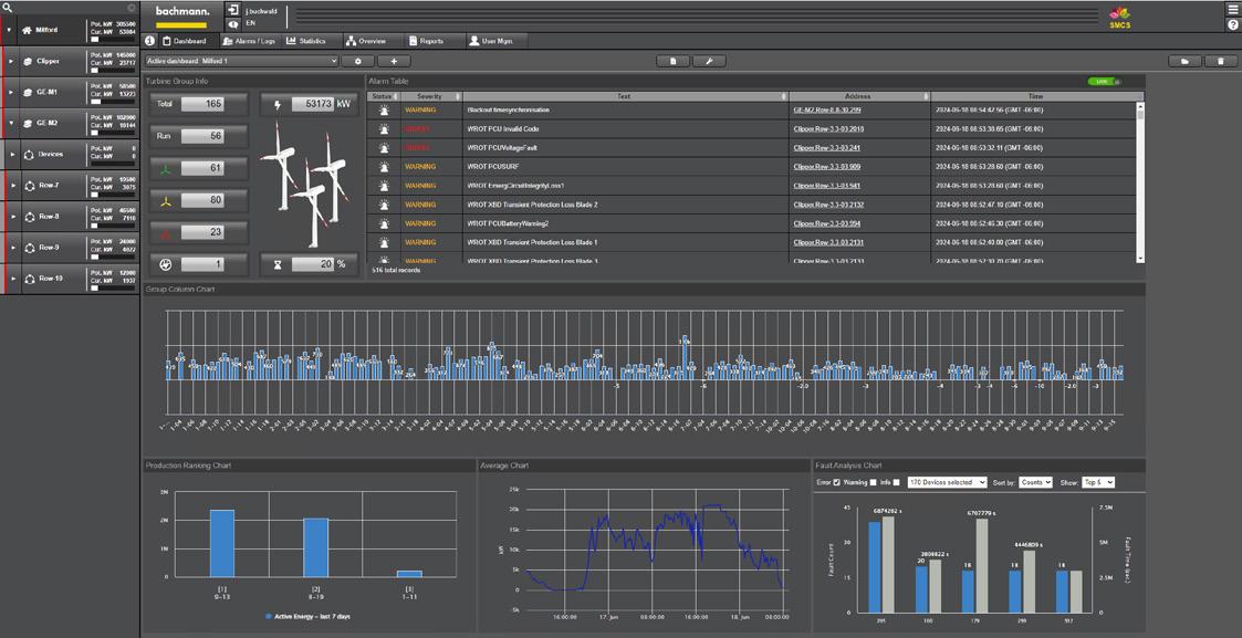
Figure 4 Visualisation tools such as forsiteSCADA provide a comprehensive view of the entire wind farm and the individual turbines.
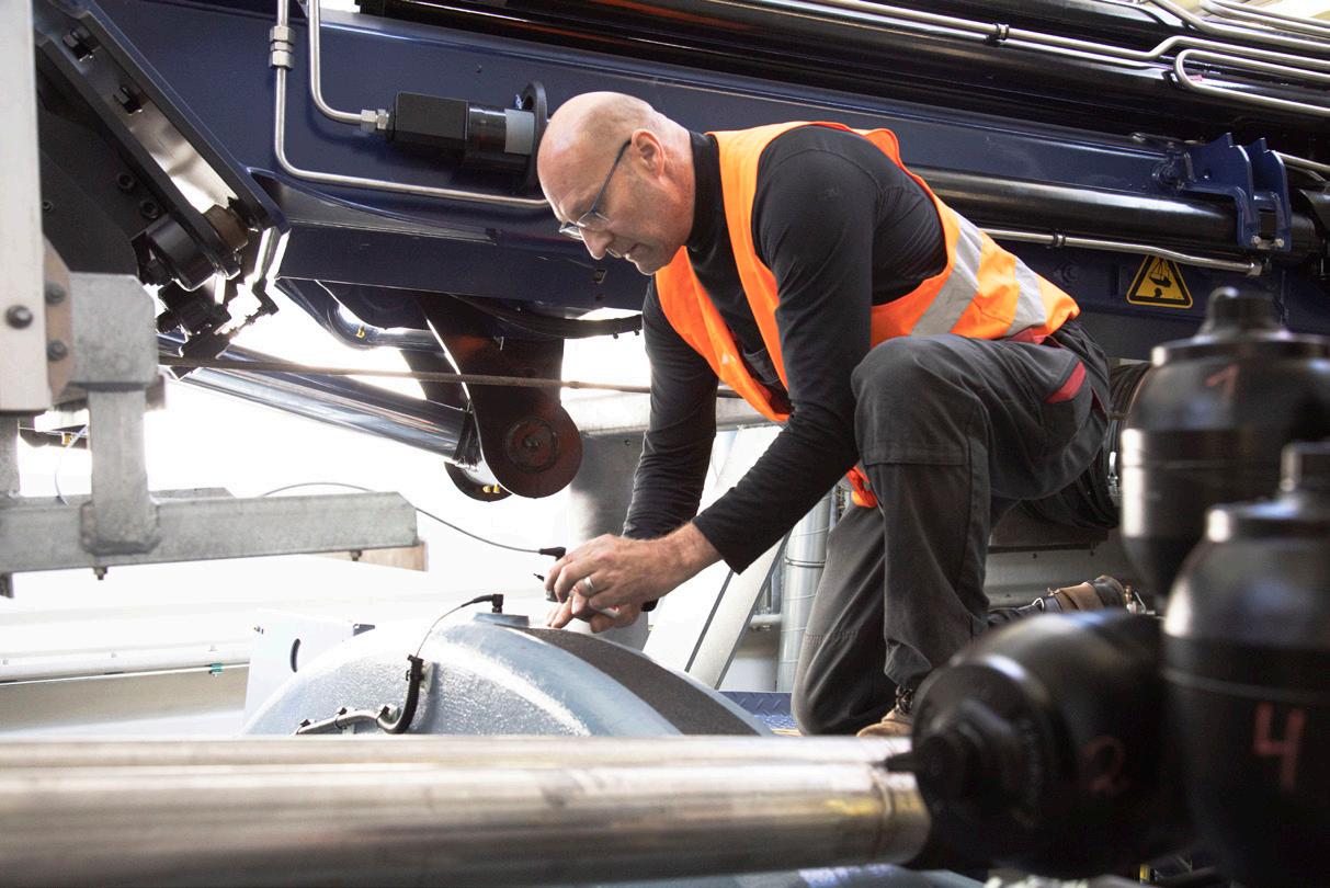
Figure 2 High-precision structural health monitoring measurements can extend the lifetime of wind turbines in many cases. Here is a service team installing an acceleration sensor, which plays an important role in data acquisition.
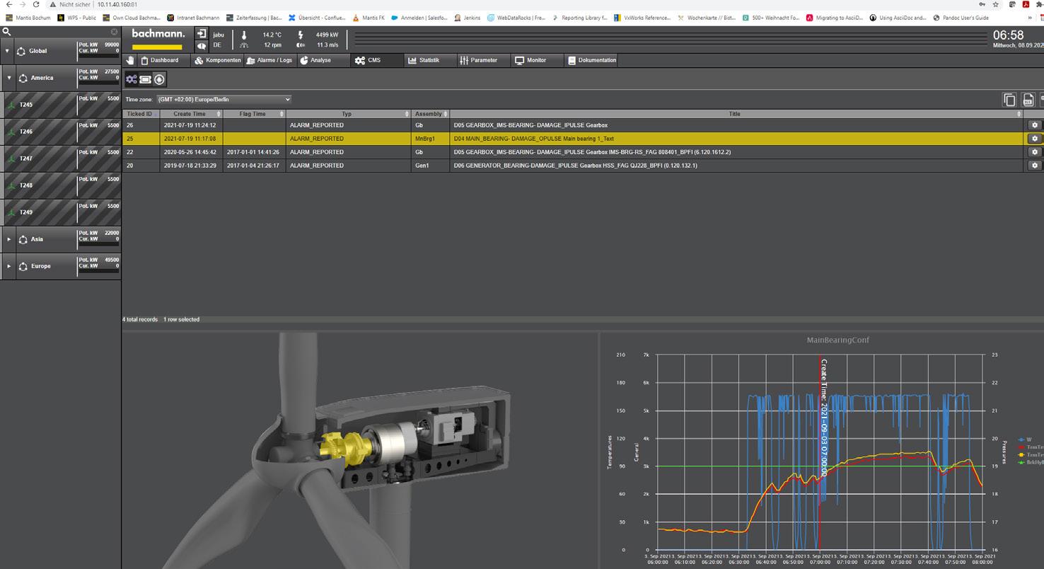
Figure 3 Transparent monitoring and data security are at the centre of the condition monitoring services offered by service providers such as Bachmann. Customers should have complete access to all condition monitoring system (CMS) data and a complete overview of the status of their systems.
Located near the small town of Milford in Beaver County, Utah, the Longroad Energy wind farm consists of 57 GE 1.5 SLE, 11 GE 1.5 ESS, 39 GE 1.5 XLE turbines, and 58 Clipper Liberty 2.5 turbines. The operator wanted to control and monitor the entire wind farm safely and efficiently from its operations centre. The plan was to use a modern SCADA platform design incorporating the latest cybersecurity measures, while delivering complete access to assets. Bachmann had a good reputation at Longroad due to its control systems in the GE wind turbines.
Higher reliability and productivity in three days
The control system was replaced to ensure continuous and safe turbine operation. The Bachmann M200 control system is now used in combination with the GMP232 module for power monitoring and grid protection. The turbine control system is connected via ‘bluecom’ – an Ethernet-based, real-time protocol from Bachmann – to the master park controller, which was also implemented by Bachmann.
In addition, the goal was to reduce gearbox load and thus increase the reliability of the Clipper turbines. Experience shows that asymmetrical stresses occur on the gearbox of this type of turbine, which can lead to problems after a few years of operation. Therefore, real-time condition monitoring of the entire drive train was integrated into the retrofit solution, with existing sensors remaining in use. The complete renewal of the turbine control system, including commissioning, took a maximum of three days per system.
One for all
Existing Bachmann controllers installed in the GE turbines were updated with a state-of-the-art processor, enabling them to be integrated into the new forsiteSCADA system.
Until now, the number of SCADA servers required was determined by wind park size. With the SMCS, Bachmann facilitates the setup of a cascaded SCADA system. Data from the various park SCADAs is correlated and summarised in a user interface with clear displays. This facilitates for alarms to be assigned to the park and the respective turbine – even if the entire asset comprises several hundred turbines.
In addition, the SMCS also allows detailed analyses of individual park turbines directly from the MCS. Thanks to web technology, it is possible to jump to the underlying forsiteSCADA servers or even directly to the turbine visualisation via quickly accessible links. There, for example, analyses are available via webMI pro using the Scope 3 software oscilloscope. Sophisticated user management and clear rights assignment ensure the highest security standards.
Thanks to the SCADA retrofit, Longroad now maintains a full overview of the entire hybrid park from its operations centre. All GE and Clipper wind turbines, as well as the complete Milford Park cascaded SPPC park controllers, can be conveniently displayed in a common user interface. Key parameters, such as individual turbine yield, are summed and displayed as an overall park key figure. The open solution supports both IEC 61400-25 and IEC 61850, and can compare different plant parameters due to the uniform data format, making it easy to integrate third-party solutions.
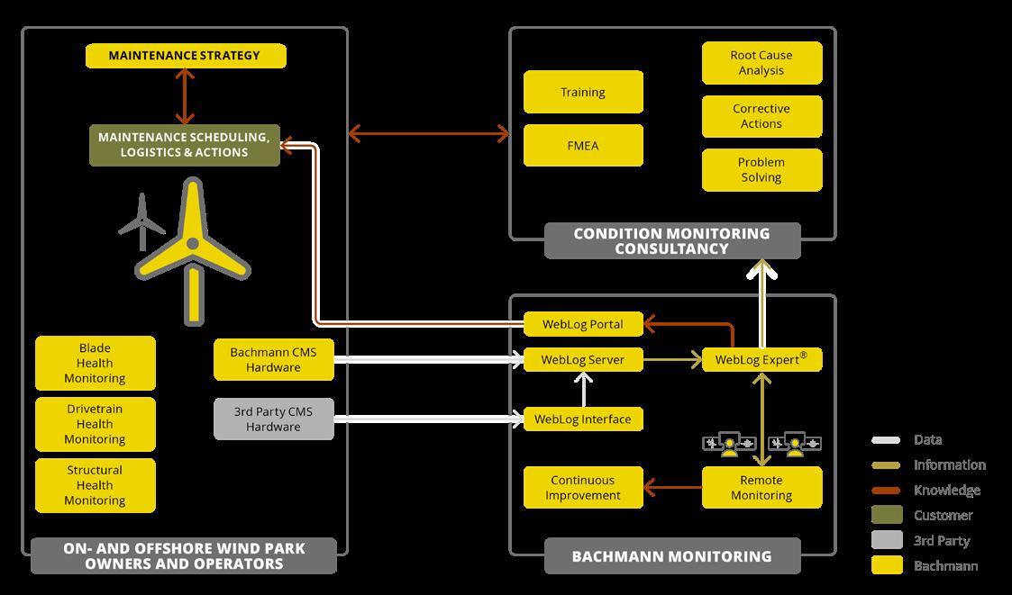
Figure 6 Specialised companies such as Bachmann offer services and expertise in condition monitoring and structural health monitoring. Depending on the desired support level, individual CMS services can be combined to create a customised monitoring and consultancy package.
Figure 7 . Bachmann’s SCADA Master Control System shows the status of all systems in a single view, even in hybrid parks. Important characteristic values are automatically summarised.
Figure 5 . Thanks to the fully prepared 1x1 m swing panels, the retrofit solution at Milford wind farm was installed quickly, which ensured a safe, reproducible rollout of all systems.
Convenient and secure, near and far
“Bachmann’s solution ensures we can continue to operate Milford 1 and 2 for years to come, while having a controller and partner capable of innovating and improving operations,” said Longroad Energy’s Jeremy Law. Moreover, the team now works in line with the latest cybersecurity standards, utilising two-factor authentication, among other features.
Another major benefit for Longroad: a uniform look and feel for service personnel when maintaining the GE and Clipper plants. Thanks to the M1 WebMI pro visualisation software, engineers no longer encounter various manufacturer-specific interfaces. The open, web-based solution has significantly increased efficiency during maintenance operations.
“With the modular approach and standardised communication of our solution, it will be easy to expand sensors or inputs/outputs for new functions in the future,” concluded Nicholas Waters, Longroad Key Account Manager at Bachmann electronic.
Individual support levels
While Longroad runs condition monitoring in house and was brought up to the latest state-of-the-art by Bachmann electronic, hybrid models are also conceivable. In this case, the operator defines the desired scope of support for condition monitoring by the external provider. After all, there may only be one piece of the puzzle missing for consistent and complete in-house performance – such as sufficient resources, infrastructure and tools, or the corresponding specialist knowledge.
A considerable reduction in the burden on in-house resources can be achieved by outsourcing data screening. For example, Bachmann Monitoring offers a service that includes hosting data and the daily routine processes for checking data quality and eliminating false alarms. Only new information relating to machinery condition are passed to the operator’s support team. An approved training package can help the operator’s team gain the required technical knowledge of vibration analysis.
Alternatively, if operators wish to establish their own monitoring without having to invest in the necessary, cost-intensive IT infrastructure, then pure data hosting is the ideal option. In a cloud solution, operators take full responsibility for their own condition monitoring. If they decide to take on data hosting at a later stage, the service provider offers the necessary tools, including licensing packages and technical support.
Reliable partnership
The decision to bring condition monitoring in house is complex, and there is no one-size-fits-all solution. For an operator who wants to retain control over the condition monitoring of their wind turbines, a hybrid solution could be the best possible option. With specialised providers, they can rely on transparent system monitoring and maximum data security. With full access to all monitoring data, they should have a complete overview of the status of their turbines, can make their own decisions, and implement their own monitoring strategy. In particularly difficult cases, however, they should have the option fall back on the advice or support of a proven service partner.

LNG Industry magazine


Andreas Hoyer, Global Commercial Director of Energy & Infrastructure, Teknos, decodes corrosion protection for the offshore wind industry, surveying coating techniques, reviewing various standards, and evaluating the effectiveness and risks associated with different coating types.
Offshore turbines are designed for an extended service life of more than 30 years to provide a sustainable form of energy generation. As offshore maintenance is considered a risky and expensive process, asset owners and operators are looking for low or zero-maintenance solutions to protect their capital assets. The challenge for the industry lies in providing coating systems that both meet regulatory requirements and have proven their performance in the field for over as long a period as possible. Of course, technology-related solutions, such as cathodic corrosion
protection and its possibilities, play a role in conjunction with coating systems. This is particularly important in areas of high mechanical stress, such as boat landings.
A new standard –
ISO 24
656: Cathodic protection of offshore wind structures
Cathodic protection (CP), possibly together with a protective coating, is applied to protect the immersed external surfaces of offshore wind farm structures and appurtenances from corrosion caused by seawater or seabed environments.
CP, possibly together with a protective coating, may be applied to protect the internal submerged surface and the seabed and sediment-exposed surfaces from corrosion. CP involves the supply of sufficient direct current to the surfaces of the structure to reduce the steel to electrolyte potential to values where corrosion is considered to be insignificant or rather low. CP is designed to protect the submerged and buried parts of the structure from corrosion. The parts that are not permanently immersed are not permanently protected by the CP system.
ISO 24 656 specifies the requirements for the external and internal CP for offshore wind farm structures. It is applicable to structures and appurtenances in contact with seawater or the seabed. The standard includes:
> Design and implementation of CP systems for new steel structures.
> Assessment of residual life of existing CP systems.
> Design and implementation of retrofit CP systems to improve the level of the protection or extend the life of the system.
> Inspection and performance monitoring of CP systems installed on existing structures.
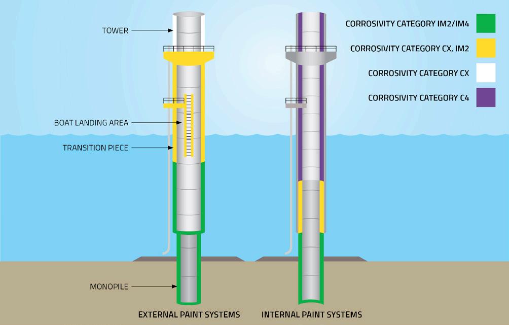
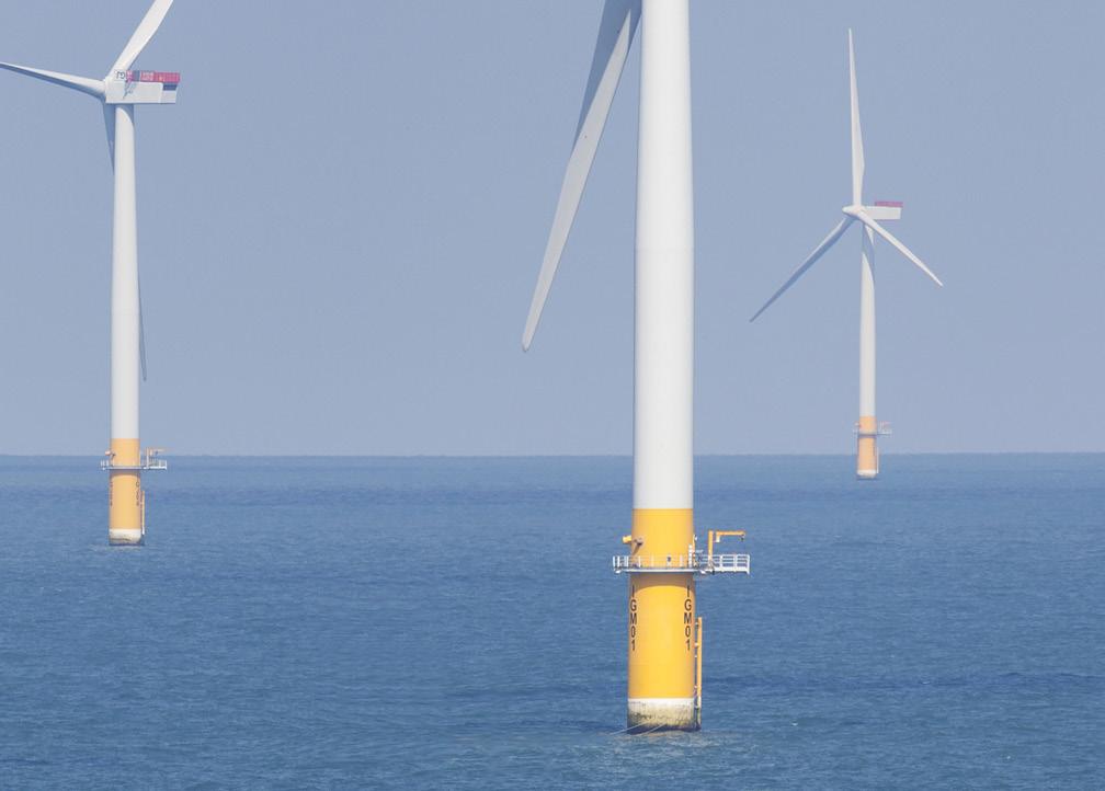
> Guidance on CP of reinforced concrete structures.
CP is often designed in combination with coatings. The ISO 12944-9 provides guidance and requirements for coatings for offshore use. Coatings alone cannot be relied upon in fully immersed areas as some progressive breakdown can be expected throughout the life of the structure. For coated structures, the CP design must consider the increased current demand over time as the coating loses its electrical resistance effectiveness. This is achieved by applying a coating breakdown factor in the formulae for calculating the current demand, the standard explains the process of coating breakdown and has suggested coating breakdown factors and breakdown rates.
Suitable coating systems for offshore wind turbine foundations are described in NORSOK M-501 as Coating System 7A/B and in ISO 12944-9 as appropriate for various environments, which are described in ISO 12944-2 as CX (offshore), Im4 (immersed) and CX and Im4 (tidal and splash zones).
DNVGL-RP-B401 further classifies coating systems for the purpose of coating breakdown for CP design into three performance categories for different epoxy, polyurethane, or vinyl-based systems. ISO 24 656 categorises five separate coating systems with categories I, II, and III being identical to the same categories in DNVGL-RP-B401, although all relate to epoxy-based coatings.
A further two categories are included to cover the increasing offshore use of more durable, higher performance coating systems. Category IV is effectively NORSOK M-501 System 7A and Category V is a glass flake filled coating system which defines both the type and content of glass flakes.
Glass flake reinforced coatings
It is important to understand that not all coatings will perform to the same level even though they may meet the technical specifications or have the same standard characteristics, including coatings that do not contain glass flake, coatings that do contain glass flake, or coatings formulated with lower or higher levels of glass flake. The corrosion performance of a coating system is not explicitly linked to one raw material –the performance is a result of the entire formulation including the technical know-how and expertise. Careful selection and optimisation of all raw materials, combined with technical expertise, helps to finely balance performance characteristics such as hardness, abrasion resistance, corrosion resistance, and flexibility.
The inclusion of glass flake in a coating product will not inherently improve corrosion performance. There are products on the market that do not contain glass flake, but they have been proven to provide extremely high levels of corrosion protection in both accelerated laboratory tests and, more importantly, over many decades of real-life application and exposure – it is this finely balanced holistic formulation that provides unique performance.
The addition of glass flake to a coating system, while not inherently improving corrosion performance, can provide a protective barrier to both extend the path to the steel substrate and improve other film characteristics such as abrasion or impact resistance. Abrasion resistance and impact resistance
Figure 1 Corrosivity zones and corresponding coating system categories for offshore wind turbine foundations, illustrating both external and internal paint system requirements for CX, C4, IM2, and IM4 environments in accordance with international standards.
Figure 2 Offshore wind turbines in operation, with clearly visible transition pieces and boat landing areas – zones subject to high mechanical stress and aggressive marine conditions, requiring robust, multi-layered corrosion protection systems.
properties are important for industrial assets to ensure that the coating system stays in-tact during construction, installation, and while in-service, additionally ensuring it is free from damage that could otherwise provide an opportunity for accelerated corrosion to occur.
What level and type of glass flake is appropriate?
Firstly, it is important to remember that not all products containing glass flake are the same and customers should refer to real world track records and experience as evidence of performance and product formulation expertise – it is the overall formulation that delivers performance and not just the addition of a specific raw material. As glass flake inclusion or content is not appropriate for corrosion performance, the Norsok M-501 standard system 7A and 7B does not dictate the use of glass flake.
However, the ISO 24 656 standard for the CP of offshore wind structures can provide a basis for specifying glass flake and glass flake content levels to achieve certain performance levels. This standard is intended to provide guidance on the combination of CP with an appropriate coating system and, by reference to this standard, a glass flake epoxy or polyester system will deliver performance in the highest corrosion category with a glass flake content of >20% by mass and through the use of lamellar glass flakes. This ISO standard should be the basis for specification when it comes to specifying glass flake content, with a minimum of 20% lamellar glass flake by mass where necessary to ensure compliance with the standard. This means that products with less than 20% are not considered to meet this coating category and therefore there is no requirement for glass flake for lower categories, allowing a non-glass flake coating to be used. It also means that coating manufacturers should ensure that high quality lamellar glass flake is used in their formulations and this should be checked by specifiers to ensure compliance. As indicated in Table D2 of the ISO 24 656 standard, the use of micronised glass flake is not as effective and should not be used.
Products containing <20% glass flake content are available on the market, e.g. it is possible for a coating manufacturer to supply a product containing 1, 2, or 3% micronised glass flake content and label the product as a glass flake product solution. There is no evidence that the performance of these products, which contain very low levels of glass flake, provide performance levels in excess of two-pack epoxy technologies that do not contain glass flake.
Simply specifying the use of a glass flake product without designating content level and type increases the risk that the performance of the coating system will not meet performance expectations and, from a commercial perspective, does not allow for a like-for-like comparison, putting fabricators, asset owners, and others in the contract chain at commercial risk. Therefore, specifiers should always link specifications to international standards as a default position as to de-risk their project specifications – i.e. ISO 24 656 for glass flake content type and performance level.
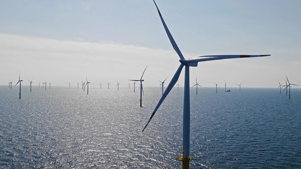
Figure 3 Aerial view of an offshore wind farm showing the extensive distribution of turbines, each of which requires tailored corrosion protection strategies for long-term structural integrity in harsh marine conditions.
Boat landing areas
Most maintenance work on offshore platforms is carried out using service vessels that approach the boat landing systems, which are secondary structures attached to the main wind turbine structure. These systems guarantee certain structural integrity conditions that can be compromised by the aggressive marine environment, which can cause corrosion processes if the structural material is not conveniently protected. The main strategy for preventing corrosion in this type of structure is the application of protective coatings, which, in this particular case, must be able to withstand not only the actual marine environment, but also against the abrasion and the impact loads generated by the violent contacts between the service vessel and the boat landing system. There are various protection solutions that can be considered, but an elastomeric polyurea coating system has proven its ability to reduce the mechanical damage to the secondary steel used.
The boat landing system consists primarily of the protective coating system plus a thick layer of an elastomeric polyurea. On impact by a berthing vessel, the steel surface transfers the load to the polyurea. The kinetic energy is absorbed and dissipated as heat and a reduced reaction force against the vessel by the elastomer as it undergoes shear and tension. The load is therefore reduced and the vessel can berth without damaging the platform structure. The strong bonding achieved between the entire coating system and the steel during the manufacturing process ensures that this arrangement will safely dissipate and reduce the external load without damaging the platform.
Bibliography
1. HOYER, A., ‘35 Jahre + | Wie können aktive und passive Korrosionsschutzmaßnahmen zur Verlängerung der Lebensdauer von Offshore WEAs beitragen?‘, Tagung Korrosionsschutz in der maritimen Technik, (24 – 25 January 2024), Hamburg.
2. NORSOK M-501, ‘Surface preparation and protective coatings’, Standards Norway, (rev. 7, 2022).
3. DNVGL-RP-0416, ‘Corrosion protection for wind turbines’, DNV GL, (March 2016).
4. ‘Paints and varnishes – Corrosion protection of steel structures by protective paint systems’, ISO 12944 (latest revision).
5. FUENTES, J. D., CICERO, S., ANDRÉS, D., and MEDIAVILLA, X., ‘Optimisation of a Corrosion-Protective Coating for a New Boat Landing System Used in Offshore Wind Turbines’, (November 2019), DOI:10.6036/9139
6. ISO 24656:2022 Cathodic protection of offshore wind structures, www.iso.org/ standard/79166.html
By 2030, wind power is anticipated to supply the bulk of the UK’s green electricity, with a significant portion of this generated by offshore installations. But innovation could help the UK make use of its exceptional offshore wind resources sooner. Alun Jones, Reflex Marine, and Laurie Thornton, MintMech, discuss a novel anchor system that could set new standards for mooring technology.
Floating offshore wind is distinct from traditional offshore wind because it relies on floating platforms tethered to the seabed. This allows for installations in deeper waters where fixed-bottom turbines cannot be used, tapping into stronger and more reliable wind resources.1
However, mooring and anchoring a floating installation is complicated. Several factors determine the ideal mooring solution, such as water depth, seafloor makeup, metocean conditions, and foundation type.
Firstly, while stronger winds might be favourable for more consistent generation of power, they also apply greater forces to the offshore installation. Secondly, as more installations are deployed and prime sites are developed, it may be necessary to install wind farms in areas with more challenging ground conditions.
A floating offshore wind farm might also need hundreds of anchors – each turbine typically requires multiple anchors to handle rare, severe storms (such as those that happen once every 50 or 100 years), and to meet insurance requirements. Therefore, any solution must be cost-effective at scale, quick to deploy, and capable of handling the loads of the mooring lines throughout the project’s life.
The oil and gas market developed many of the industry’s traditional solutions, such as drag embedment, suction pile, or driven pile anchors, where risks and requirements differ. Consequently, they can be suboptimal choices for floating offshore wind.
A new solution
JAVELIN is a slender, deep embedment anchoring solution suitable for a range of geologies, water depths, and design loads. Developed by offshore crew and cargo transfer specialist, Reflex Marine, the JAVELIN Lower Anchor (JLA) accesses the more competent strata found at greater depths in the seabed. The JLA can be locked in place with either a conventional cement grout bond or a novel aggregate locking system, which grips the sediment in a similar way to a wall-plug.
The shape of the components and novel locking mechanism of the JLA generates hoop stress, so that the more load that is applied to the anchor, the stronger the bond to the surrounding stratum, even in very weak, highly fractured ground. While still in development, the novel aggregate locking system has the potential to make installation almost instant. For example, if an installation with 50 turbines requires 250 anchors, the vessel cost and installation time can be significant.
JAVELIN is engineered to be installed at depths reaching 100 m below the seabed, which is about twice as deep as conventional driven or suction piles. This enables it to tap into stronger geological formations, allowing for a smaller steel diameter. As a result, boreholes can be drilled much more quickly than with large-diameter alternatives, and the anchors can be installed using straightforward drilling techniques from a range of suitable vessels.
The slender design of the JAVELIN anchor allows for it to be handled just like a section of drill string. With simple,
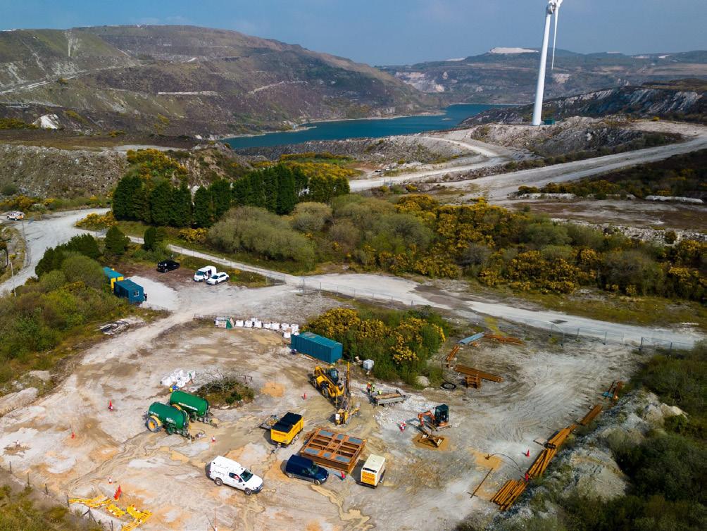
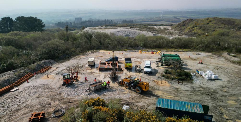
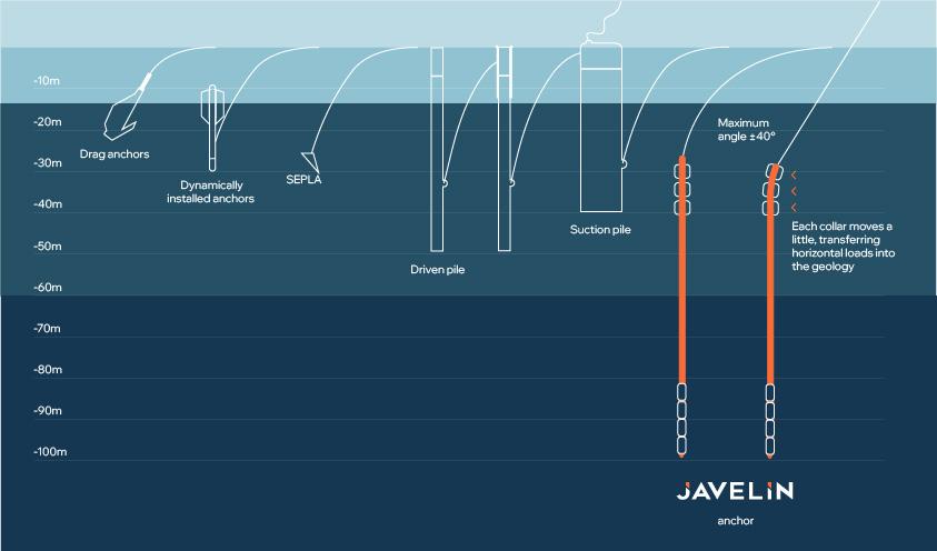
retrofittable upgrades, many vessels can be adapted to both drill the borehole and install the anchor, removing the need for expensive, dedicated deployment systems.
Development timeline
Reflex Marine first commissioned MintMech ahead of initial scale testing at a site in Cornwall. MintMech helped optimise the designs of the key components, such as the anchor’s tapered cones and other specialised parts, and fabricated a test rig.
The initial proof of concept was an iterative process and quite labour intensive, as it required gathering as much data as possible. For the second phase, testing was moved to a controlled environment inside a dedicated facility near Yatton, Somerset, which necessitated a new test rig and collaboration with a specialist engineering company.
The Yatton rig was larger and more complex than the first, incorporating a structural support frame with a pneumatic cylinder, load cell, and strain gauges. It also featured a rotating steel pipe to simulate the borehole.
The successful trials secured further funding for Reflex Marine, including an award from the Department for Business, Energy & Industrial Strategy (BEIS) that supported the project’s third phase: testing at a former China clay mining site in Cornwall. MintMech designed and built all the testing rigs used to load the anchors during these land trials, with loads escalating from 10 t initially to over 350 t.
Testing at Blackpool Pit facilitated the analysis of JAVELIN’s performance in geology similar to that of the Celtic Sea. The site also had mudstone with varying rock quality designations at different depths, making it an ideal test location.
A 1:3 scale JAVELIN installed in a 10 cm borehole beneath 6 m of densified aggregate held 100 t of load, while a 1:1.5 scale anchor beneath 12 m of aggregate held firm at 361 t. In both tests, the steel strand attached to the anchor failed before JAVELIN’s grip did. Equipment capable of sustaining a 1000 t land test has already been commissioned, with MintMech contributing to the design, engineering, and manufacturing of the tensioning and load dissemination systems. The final stage of the prototype development will involve offshore trials.
Many innovative anchor technologies are currently in development, but this is one of the most extensively field-tested solutions. At a recent presentation by MintMech and Reflex Marine, they were the only ones at the event with photographs showing their work in action. While designs, theories, and 3D renders have their place, the real challenge lies in fabricating anchors, installing them, and putting them to the test.
Looking to the future
Floating offshore wind presents a major opportunity for UK renewable energy, but its viability hinges on addressing key engineering challenges. Collaborations, such as those between Reflex Marine and MintMech, can help develop a solution that tackles both the technical obstacles and the practical and economic realities of scaling up floating offshore wind installations.
References
1. ‘Future of Offshore Wind: Considerations for development and leasing to 2030 and beyond’, The Crown Estate, (September 2024), www.datocms-assets. com/136653/1725984848-tce_future-offshore-wind.pdf
Figure 1 Aerial shot of the testing facility, Blackpool Pit near St. Agnes, Cornwall.
Figure 2 . Blackpool Pit is a disused China clay pit with similar geology to that of the Celtic Sea.
Figure 3 . The JAVELIN anchoring system reaches much deeper ground than conventional solutions.
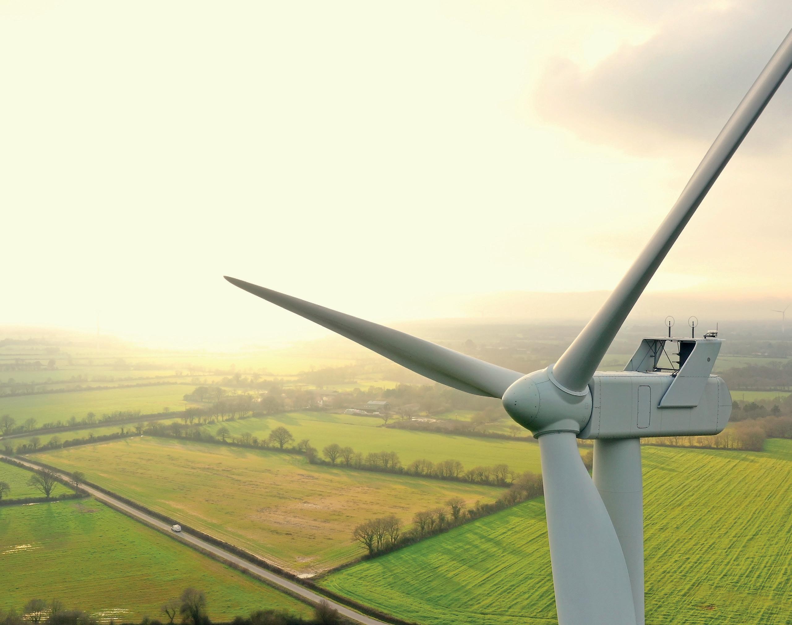
Subscribe online at: www.energyglobal.com/magazine
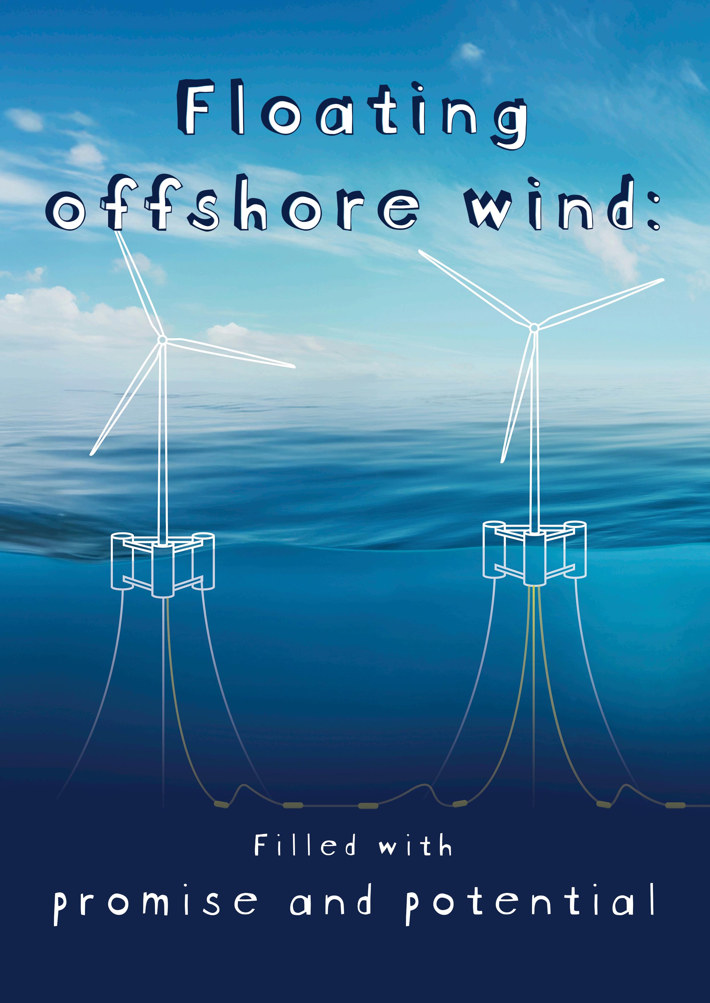
Sille Grjotheim, Global Segment Director, Floating Offshore Wind, and Alireza Bayat, Principal Consultant, Energy Systems, DNV, provide an overview of the evolution of floating offshore wind from concept to deployment.
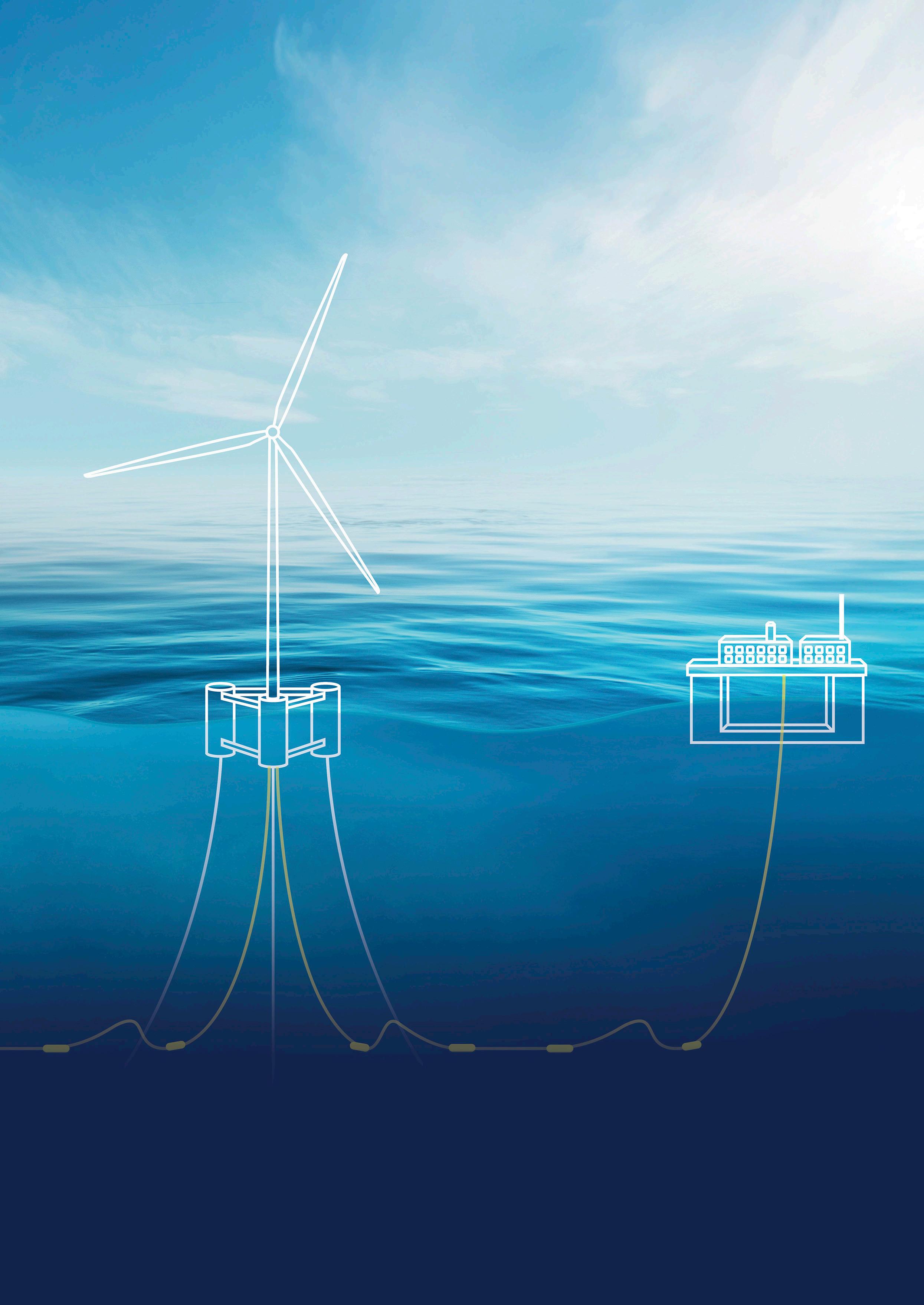
Despite being in its relative infancy compared to other renewable technologies, there is a general understanding that floating offshore will be a critical component in the energy sector’s efforts to meet net-zero targets. According to Navitas, the global floating offshore wind market is currently valued at US$1.15 billion and projected to skyrocket to US$177.32 billion by 2037 at a 52.1% CAGR, underlining the incredible potential for the sector.1
But developers, supply chain, and investors will have to overcome many challenges if they are to realise the potential and the future that is undoubtedly floating. Bottlenecks, rising costs, and rampant delays threaten to undermine the scale up of the sector, but there are solutions.
Climate goals must be matched by national and global energy security. For many countries, floating offshore wind will be a key way of harnessing green
energy while simultaneously reducing dependence on imported fossil fuels.
An evolving sector
Floating offshore wind is currently moving from the demonstration phase into commercialisation, with DNV forecasting in its 2024 Energy Transition Outlook (ETO) report that the sector will be responsible for a capacity of up to 200 GW by 2050. This shows a y/y increase in this sector, with just 0.3 GW of floating offshore wind capacity currently operational globally.
This predicted increase in floating offshore wind off the coast of countries around the world is illustrative of the sectors potential, as well as the willingness of experts and major energy industry players to invest time and money.
But for all this focus, costs remain high, with supply chain issues and considerable delays having a significant impact and thereby slowing the sector’s ability to reach the
Figure 1 . Illustration of a floating offshore wind farm.
scale and commercial viability needed to drive the energy transition forward.
Floating offshore wind projects are complex with many different stakeholders and contractors involved. In response to complex industry issues and to aid developers, DNV has merged its experience and well-proven third-party assurance models for the maritime and offshore wind industry –classification and certification – into one harmonised solution that provides compliance with both schemes. By combining this with selected advisory services, it allows project developers to provide utmost confidence to investors and insurance companies.
DNV’s third-party assurance service for floating offshore wind will allow for new collaboration and alliances between stakeholders that come from different backgrounds. The streamlined assurance service ensures safe and reliable projects as risks are addressed in an optimal way for floating offshore wind – all in one.
It allows for integrating a DNV-classed floating substructure and mooring system into project certification. As well as reducing costs, this set up increases quality and helps customers to achieve operational excellence.
However, this does not eliminate all the issues that the sector is facing, with project developers needing to navigate multiple blockers as they move from concept to deployment.
Barriers to scale: Heightened costs, delays, and supply chain disruption
In a talk by DNV at Norwegian Offshore Wind’s Floating Wind Days event, various issues currently affecting the sector came to the fore. Rising costs (associated with materials, labour, and specialised equipment) have blended with supply chain disruptions to severely challenge project economics, threatening the financial viability of projects.
One of the largest factors currently hindering the floating wind sector is the robustness of the supply chain; there are considerable bottlenecks leading to significant strains and delays.
DNVs latest ETO predicts that more than 200 GW of electricity will be generated by floating offshore wind by 2050. Achieving this will require developers to deliver vast infrastructure at pace, with tens of thousands of floating turbines and mooring lines, along with millions of tonnes of steel. This will require a significant manufacturing effort, major investment, and government support.
Perhaps the largest issue facing the supply chain, however, is the demand for cables, which are currently the only way of transmitting energy from far out at sea to shore. The demand on cable factories has seen order lists grow exponentially, with most suppliers fully booked for the next 5 – 7 years.
Global floating offshore wind projects are expected to require tens of thousands of inter array cables, putting notable strain on an industry already experiencing substantial delays. Meanwhile, the total amount of floating substructures that will need to be manufactured per year to meet the sectors targets sits at a staggering 400.
Beyond supply chain challenges, the sector is also grappling with intense pressure on vessels. Floating offshore wind will require a vast number of tugs for towing foundations and, in the operational and maintenance phase, service vessels. At the same time, the sector will be competing with oil and gas companies, which are generally more able and willing to splash out on the higher rates. Compounding the problem, low oil and gas prices from 2014 – 2024 meant that investment in new vessels was low, causing additional bottlenecks across the board.
Challenges around political stability also significantly affect floating offshore wind developments, as a lack of clarity on regulatory frameworks and the pipeline of projects adds risks to the developers and may cause delays and cancellations. DNV also offers support in this area by engaging with governments around the globe to aid them in learning from each other and applying best practices. This allows governments to regulate this sector in the most cost-efficient way possible, helping pave the path for their countries’ energy security and independence.
The future of the sector
As a result of these issues the levelized cost of energy (LCOE) for floating wind has increased in most regions, with proposals and projects getting postponed across the board. Floating offshore wind currently boasts the highest LCOE of any wind technology, significantly above that of fixed bottom wind and onshore wind. However, DNV predicts the cost gap between fixed and floating offshore wind to diminish rapidly over the next 25 years, with projections indicating the difference will settle at around US$29/MWh by 2050. By then, the LCOE of fixed offshore wind is predicted to sit at around US$67/MWh and floating at US$96/MWh on average around the globe. Some markets indicate they will be able to reduce the LCOE for floating even further.
Significant investment in the floating wind sector is needed to overcome these obstacles and to allow it to succeed. But despite issues, the floating offshore wind sector is very much still alive, with over 100 floating offshore wind concepts currently being developed in parallel and more than 350 projects where these concepts might be used in progress (under development, planned, or potential).2 Turning these concepts into reality will require developers to work together and foster a spirit of consolidation and collaboration.
Technology readiness level
The downside to having so many concepts floating around, with so many factors and nuances to consider, is that it is incredibly difficult for developers to identify the best technology for their project. DNV is well-positioned to advise on this, with over 500 employees working full time on wind and many more part-time. Its global presence in almost 100 countries with floating wind experts in key markets helps to start this process by aiding entrance into new markets.
Concepts must also be judged and considered to ensure feasibility and ultimately success. DNV has ranked over 50 of today’s floating offshore wind concepts through a
metric called technology readiness level. This metric tests how mature and ready the technology is to be deployed and operational. The company considers factors such as scalability, risk assessment, regulatory compliance, economic viability, and environmental impact, as well as cost and weight and availability of necessary materials required.
Large focus is placed on reducing the investment required to manufacture turbines, especially with the cost of raw materials rising exponentially. The ease of fabrication and operation is also incredibly important as these factors will have an impact on a supply chain that is already stretched. Streamlining the manufacturing process and then allowing for seamless installation and operation is key to launching a successful floating offshore wind project.
A digital tool to aid understanding
Another piece of technology developed by DNV to tackle these issues is a new digital tool, Renewables.Architect. This system analyses a wind farm using a systems engineering approach. Various models are connected to a single analysis for early-stage design on a systems level, allowing developers to optimise the LCOE for wind installations during concept design. Models considered by this software include turbine and floating structure, energy yield, operations such as transport, installation, and maintenance, as well as cabling. Giving developers a whole systems engineering view allows for more efficient and cost-effective operations, ultimately setting up the project for success.
Securing a floating future
The floating offshore wind sector is at an inflection point where promise and potential are counterbalanced by the scale and breadth of the challenges. The journey from demonstration to commercialisation is fraught with complex issues such as supply chain bottlenecks, exponentially rising costs, infrastructure demands, and nuanced environmental challenges.
Unlocking the full potential of floating offshore wind will require concerted effort rooted in collaboration, strategic investment, and decisive action to streamline manufacturing and strengthen the entire supply chain. Industry leaders, such as DNV, are paving the way for this by providing technology development, technical assurance, advancing digital innovation, and leveraging its vast experience and reach to help developers and new entrance navigate the rapidly growing floating offshore wind landscape.
Ultimately, the future of this industry will be shaped not only by technological breakthroughs but by a shared commitment to overcoming challenges and transforming bold ambitions into tangible reality.
References
1. ‘Floating Offshore Wind: Unlocking New Fronteirs in Renewable Energy in 2025’, Navitas, (21 May 2025), https://navitas-nrg.com/floating-offshore-wind-unlocking-newfrontiers-in-renewable-energy-in-2025/
2. ‘Renewables Intelligence Network’, Clarksons Research, www.clarksons.net/rin
Global Hydrogen Review Online


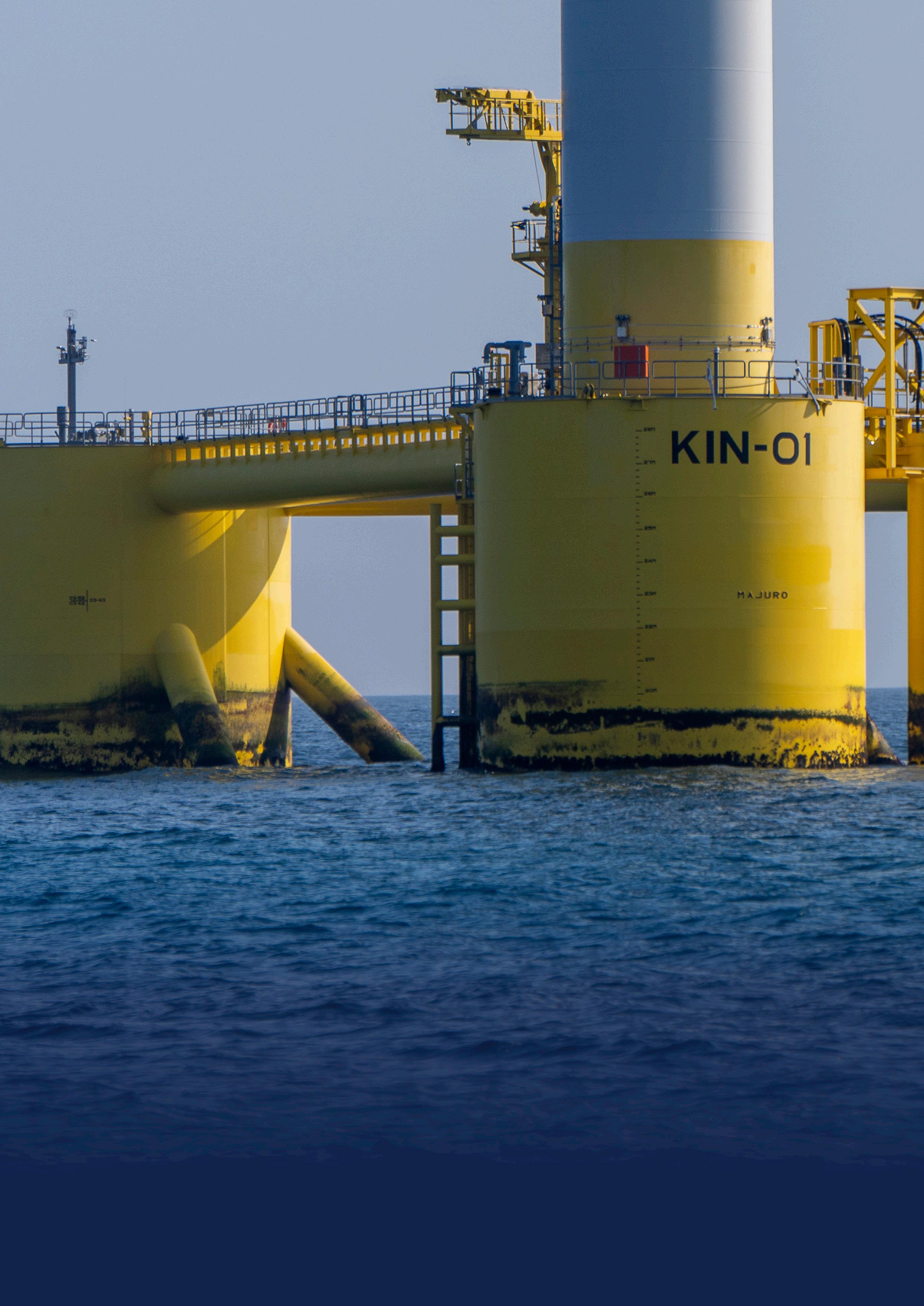
Figure 1 Projects such as Green Volt are carving a path for the floating offshore wind projects of tomorrow.
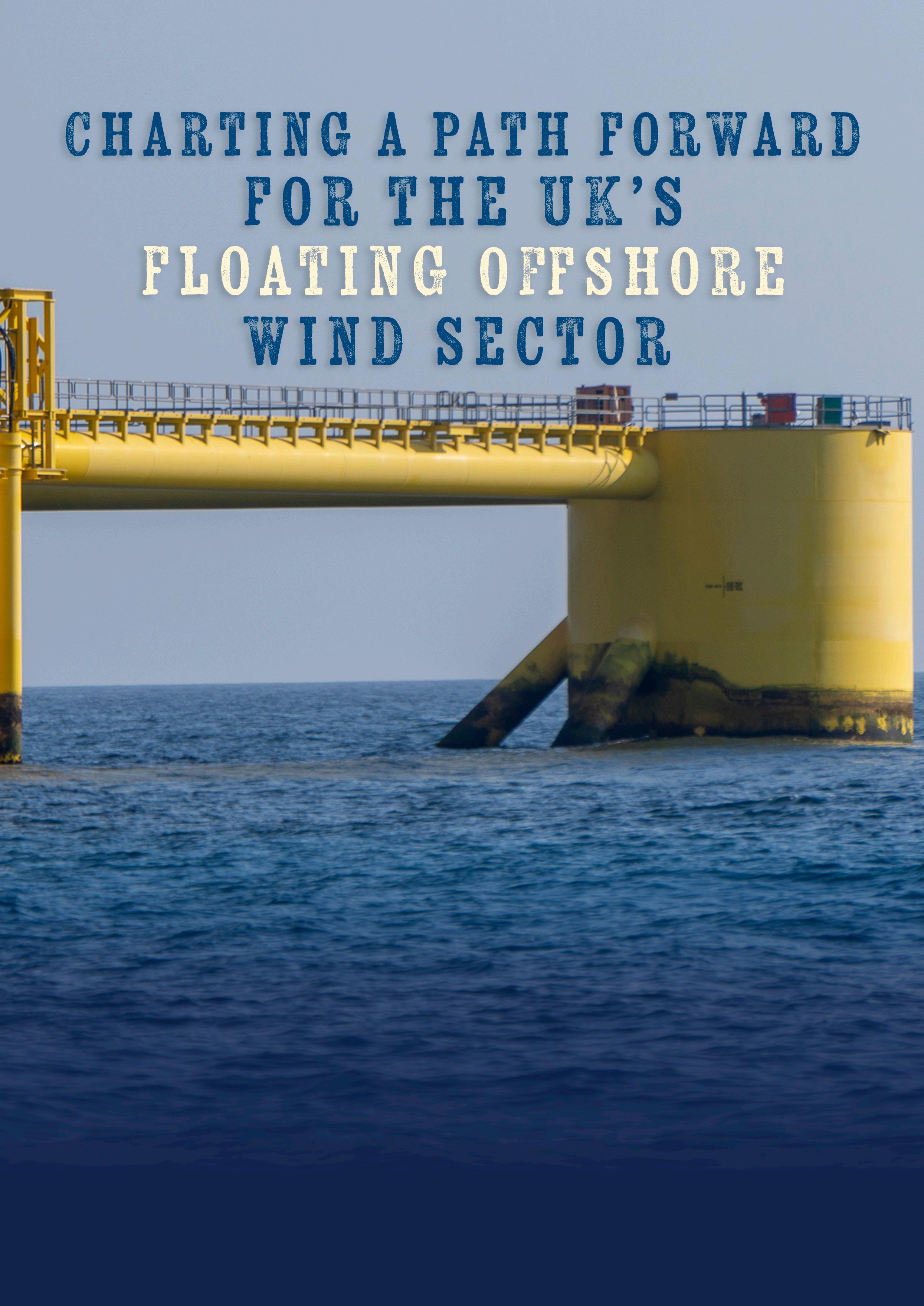
Matt Green, Green Volt Project Director, details the importance of floating offshore wind for the UK’s renewable energy targets and sketches out the path ahead.
Offshore wind is a key part of the UK’s energy mix and will remain vitally important as the country transitions to a cleaner energy system, racing to reach net zero. In its Clean Power Action Plan, the UK government has set a hugely ambitious goal of reaching 43 – 50 GW of offshore wind by 2030 and, to meet this goal, floating wind technology will be key.1
Floating turbines can be built in deeper waters to harness the greater wind resource found far out at sea, where there are stronger and more consistent wind speeds. By unlocking these areas, more clean energy can be produced and the industry’s ability to reach sustainability targets is more easily realised. Floating platforms are also more adaptable to different seabed conditions, reducing the need for expensive seabed preparation.
Already, the floating offshore wind market is scaling up significantly in the UK, which is home to the Green Volt project – set to become the largest commercial scale floating offshore wind farm in the world.2 The European market paints a similar picture, with Norway opening its first floating wind tender in May 2025.
While these wind farm developments present an exciting opportunity to harness the sustainable energy of the future, like any new market, the floating offshore wind sector faces challenges. Headwinds such as a lack of port infrastructure and manufacturing capabilities pose obstacles in the immediate term but, thankfully, large developments like Green Volt will act as a springboard for the local supply chain.
Based off the North East coast of Scotland, Green Volt is a first mover in floating offshore wind and is charting a path forward for future developments to follow.
Making rapid progress towards getting online
Located 50 miles off the coast of Peterhead, Green Volt will consist of up to 35 floating turbines generating 560 MW of electricity. As a brownfield oil and gas site in the process of being decommissioned, the area was deemed the optimal zone for the wind farm due to its high-quality wind resource and 90 – 100 m water depths.
With this site in place, following a successful bid at the Crown Estate Scotland INTOG Leasing Round, the project is moving forward at a rapid pace. Having secured a Contract for Difference from the UK government in 2024, developers Flotation Energy and Vårgrønn, are now focused on delivery.
2025 is set to be a standout year for the project. In the first few months, Green Volt has reached major milestones including the announcement of its headquarters in Aberdeen, which is the traditional hub of the UK’s energy industry. This builds on five years of project planning, harnessing the ongoing momentum around renewables in the region, and delivers up to 40 direct jobs in the city.
Technical milestones have also been achieved, particularly around securing the infrastructure required for the project. The FEED Phase 1 is progressing to deliver the EPC of an offshore substation, encompassing both the jacket and topsides, and the design of the high voltage equipment. Looking to the future of the FEED process, Phase 2 is also on the horizon, encompassing the
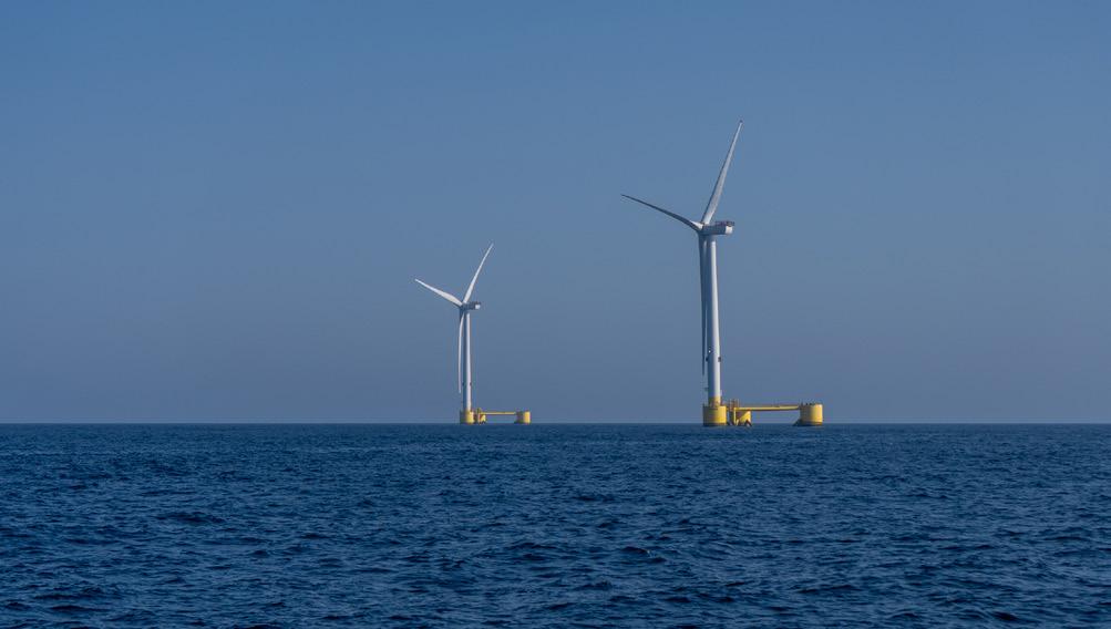
main structural project, with the contract due to be awarded by the end of 2025.
Geophysical and geotechnical surveys are ongoing, with Phase 1 of Green Volt’s survey work in the western side of the array area completed in May 2025 and Phase 2 planned for summer 2025. These surveys are essential for understanding the subsurface conditions of the area, to help inform the design and installation of floating offshore wind project infrastructure.
Specifically, geophysical surveys assess seabed conditions, map geological features, and identify potential hazards, and thereby ensure the stability of floating platforms. Geotechnical surveys, however, focus on the properties of the seabed and subsoil, such as soil composition, strength, and stability, ensuring the integrity of foundations or anchors. Together, these surveys minimise risks, reduce costs, and enhance the safety and efficiency of offshore wind farms while supporting regulatory compliance.
At Green Volt, geotechnical surveys are currently ongoing for the development of onshore cable corridors, alongside other essential ground condition assessments and environmental studies. These studies support the gathering of critical data to inform the next stage of development and design for the corridors, ensuring they meet efficiency and environmental standards.
Designed to minimise impact on the surrounding environment and existing infrastructure, onshore cable corridors are also crucial for connecting floating offshore wind farms to the national electricity grid. The underground cables transport electricity from the landfall point, where subsea cables meet land, to onshore substations, facilitating the integration of renewable energy into the grid.
All these behind-the-scenes works put the Green Volt project on track to become the first commercial scale floating offshore wind farm in Europe. The project is set to deliver over £2.5 billion in gross value added, with £1.3 billion of this added to the UK economy alone.3
Boosting the supply chain and engaging the local community
Infrastructure projects of Green Volt’s scale require input and consultation with many different stakeholders. With the transmission cables making landfall close to Peterhead, the project team dedicates time to meet with the community of Peterhead every week and has done so since March 2024. As a result, essential discussions with community representatives have been ongoing and local people are given the chance to discuss any concerns about the implications of the wind farm and its construction.
The Green Volt project team has also engaged with local schools to encourage young people in the area to embrace STEM subjects, helping ensure a strong pipeline of talent for future wind developments. This includes Peterhead Academy, where members of the Green Volt team recently shared their own career stories from working in the energy sector while leading interactive workshops.
In 2024, an ORE Catapult report outlined that the offshore wind workforce must increase from the current 32 000 value to 100 000 people by 2030 in order to meet the decarbonisation targets set by the UK government and the
Figure 2 . The floating offshore wind market is scaling up significantly in the UK, which is home to the Green Volt project.
organisation called for more investment in floating wind skill development.4 By engaging with the local community and inspiring the next generation, the Green Volt project supports the wider industry and helps protect its future.
The project significantly impacts the wider industry and businesses operating in the offshore wind and construction sector, not just the local community. Green Volt is estimated to deliver over 2800 direct jobs during construction, helping to develop the UK supply chain further.5 This is particularly true in the case of Scottish ports, with the project adopting a multi-port strategy that will spread risk and help to upskill teams across multiple organisations.
Paving the way for future floating wind projects
Projects such as Green Volt are carving a path for the floating offshore wind projects of tomorrow by acting as a springboard for the UK’s floating wind supply chain and reducing infrastructure pressures for future new-build projects. As the project continues to work towards completion in 2029, infrastructure and manufacturing capabilities, as well as more standardised technologies, will naturally become more efficient. This will open opportunities for easier project implementation across the UK’s renewables market, driving a more diverse and secure sector.
Once online, the wind farm will supply 1.5 TWh of clean electricity to the UK grid and save 1 million tpy of CO2. In delivering these benefits, the Green Volt project and future projects like it are set to play an essential role in meeting national climate goals.

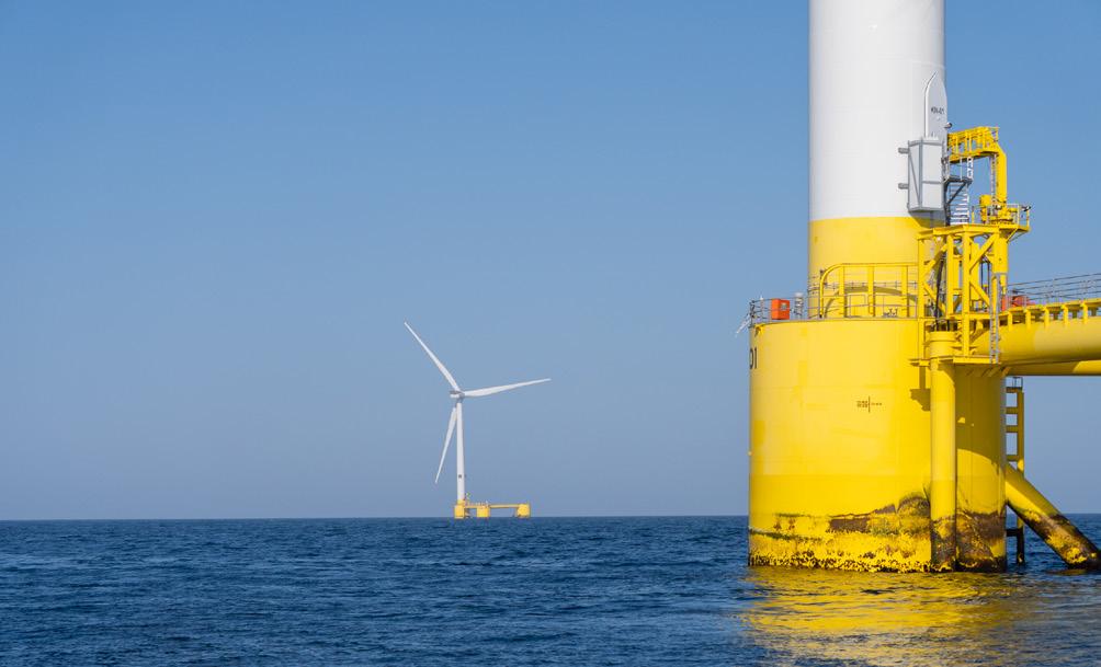
Figure 3 Having secured a Contract for Difference in 2024, developers Flotation Energy and Vårgrønn are focused on delivery of the Green
References
1. ‘Clean Power 2030 Action Plan: A new era of clean electricity – main report’, Department for Energy Security & Net Zero, (15 April 2025), www.gov.uk/ government/publications/clean-power-2030-action-plan/clean-power-2030action-plan-a-new-era-of-clean-electricity-main-report
2. ‘New growth and employment opportunities as next generation of offshore wind reaches critical milestone’, The Crown Estate, (7 April 2025), www.thecrownestate. co.uk/news/new-growth-and-employment-opportunities-as-next-generation-ofoffshore-wind-reaches-critical-milestone
3. ‘The first commercial-scale floating wind farm in Europe’, Green Volt (9 April 2024), www.crownestatescotland.com/sites/default/files/2024-04/Green_ Volt_Supply_Chain_Development_Statement_Outlook.pdf
4. ‘ORE Catapult calls for skills investment’, ReNews, (28 February 2024), https://renews.biz/91555/ore-catapult-calls-for-floating-wind-skills-investment/
5. ‘£2.5bn Green Volt floating windfarm selects Aberdeen for new HQ’, Flotation Energy, (11 October 2024), https://flotationenergy.com/2-5bn-green-voltfloating-windfarm-selects-aberdeen-for-new-hq/
LNG Industry Website


Volt wind farm.
Svante Bundgaard, CEO, and Jens Taggart Pelle, Vice President of Technical Sales, Aalborg CSP, advocate for the conversion of coal-fired power plants into thermal storage facilities for renewable energy, saving time and costs towards advancing the energy transition.
Asubstantial increase in the amount of intermittent renewable energy produced is to be expected in the coming years, and this will require storage of energy from wind turbines and solar parks if current consumption patterns are to be maintained. At the same time, existing coal-fired power plants must be phased out. Therefore, it is ideal to reuse coal-fired power plants for storing renewable energy instead of demolishing them and building new energy storage facilities from scratch.
The need to store energy from solar panels and wind turbines in an efficient and flexible way will increase significantly in the years to come. There are advantages to storing renewable energy and saving it for later use when there are peak loads on the grid and when renewable energy production is low. This is why Danish company, Aalborg CSP, an expert in renewable energy, sees great potential in building storage facilities that promote the energy transition.

Aalborg CSP has developed a solution that transforms existing coal-fired power plants into large scale energy storage facilities. With many plants scheduled for decommissioning as part of the global green transition, Aalborg CSP’s approach offers a smart alternative: rather than dismantling existing infrastructure, there is a solution that reuses most of the installed equipment, preserves local jobs, and provides cost-effective energy storage and regional security for the supply of electricity. Drawing on proven large scale CSP applications, this concept enables the continued use of existing sites for energy purposes, while allowing new energy storage infrastructure to be built where it is needed most.
In Europe, there are more than 250 coal-fired power plants that have an impact on the environment and climate due to their high consumption of fossil fuels. Many of these power plants will be phased out as carbon dioxide (CO2) emissions must be reduced significantly in the coming years,

meaning that power plant owners will be left with outdated facilities if they are not converted.
There are hopes that, in addition to the environmental and climate-related benefits, owners of coal-fired power plants will see a good business case in replacing coal-fired power plants with energy storage facilities. Plant owners will save on the costs of decommissioning and dismantling coal-fired power plants, which are scrap if they can no longer produce energy.
Aalborg CSP’s calculations show that repurposing coal-fired power plants is the most cost-effective solution as the equipment is already installed and is fully functional for many years to come. In addition, plant owners will see a reduction in fuel costs by charging with excess renewable energy from the grid and can generate new revenue both through balancing services to the electricity market and arbitrage with the sale of the stored electricity. At the same time, plant owners will experience lower operating and maintenance costs on an energy storage facility due to fewer mechanical moving parts. Likewise, the owners’ public image could be boosted as the conversion would provide security of electricity supply in unstable times, making a huge effort to create a sustainable future energy production.
Power-to-Salt solutions
Converting coal-fired power plants, and thus supporting the transition to a more sustainable energy future, can be achieved by Aalborg CSP’s offering of Power-to-Salt solutions.
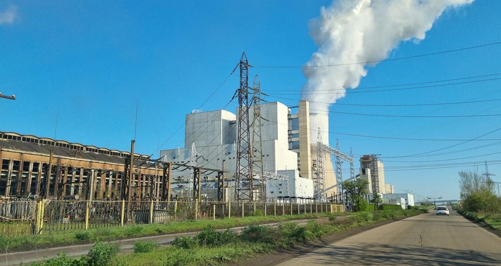
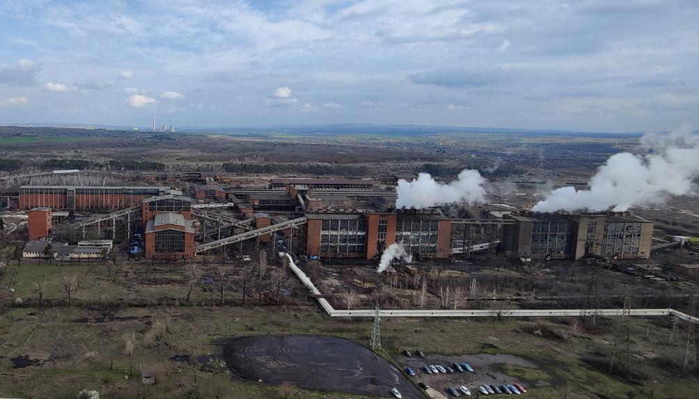
Using a Carnot battery, the company can convert electricity into thermal energy. The battery works by converting excess electricity from green energy sources, such as wind turbines and solar panels, into heat. The heat is then stored in molten salt and, when demand for electricity increases, the heat is converted back into electricity.
As part of the conversion, the coal-fired boiler is replaced with a steam generator system based on Header & Coil technology, powered by hot molten salt heated up to 565˚C. The molten salt is stored in two insulated tanks and is used to generate high-temperature, high-pressure steam, which drives the existing power plant turbines to produce electricity –eliminating the need for fossil fuel combustion while retaining much of the original infrastructure.
There is great potential in transforming coal-fired power plants around the world with this technology. In Europe alone, 250+ existing coal-fired power plants could be converted into energy storage facilities for renewable energy. It is not appropriate for anyone to shut down existing power plants completely, as this would result in significant losses for the owners and require a lot of resources to decommission the plants. On the other hand, it is a good idea to reuse components such as steam turbines, generators, and grid connections in the new energy plant.
There are many advantages of Carnot battery technology. For example, it utilises surplus electricity, provides grid stability through its ancillary services to the grid, such as frequency regulation and reserve capacity, and can also be scaled to match local grid needs in the future. Carnot batteries have a long lifespan as the molten salt involved has a long operational life with low degradation. These batteries can be deployed quickly, meaning that the conversion of existing plants can be faster than building entirely new facilities. Some other advantages include:
> Cost-effective energy storage.
> Security of supply.
> Supply and demand balance.
> Increase in flexibility.
> Support of electrification.
> Re-utilisation of existing infrastructure.
> Preservation of local jobs.
By using Aalborg CSP storage technology, it is therefore possible to strengthen the security of supply and create a balance between supply and demand. The technology can help maintain the frequency in the grid, as the system can be regulated to an unprecedented extent.
An alternative to completely stopping the use of fossil fuels at coal-fired power plants is to reduce the amount of coal used in energy production. Depending on individual needs, the solution may be an addition to an existing energy source or a stand-alone unit, however, in most cases it is most appropriate to eliminate fossil fuels altogether.
Most of the existing infrastructure of coal-fired power plants can be reused for electricity production. Original components such as steam turbines, generators, and heat exchangers, as well as components for switching,
Figure 2 . In close collaboration with AES, Aalborg has analysed how to create a future-proof solution by converting the coal-fired power plant into an energy storage facility.
Figure 1 Aalborg CSP is collaborating with AES Bulgaria to investigate the possibility of converting a large coal-fired power plant in Bulgaria.
transforming, and transmitting high-voltage electricity, can be reused in the new energy plant.
In addition, it is also a major advantage to retain local jobs at the power plants and turn them into ‘green’ jobs in the operation and maintenance of the future plants.
The need for renewable energy will increase significantly in the coming years, and, due to its intermittent and unstable nature, a solution that can match energy production and consumption is needed. Therefore, energy storage is at the forefront of developments in renewable energy, and one of the major challenges in large parts of the world. Various solutions already exist, and Aalborg CSP have a proven concept that can be scaled as needed. There is a great need for decisions that promote large scale energy storage as part of grid infrastructure, utilising energy from wind turbines and solar panels. At the same time, there is a need to solve the challenges posed by coal-fired power plants, which should be taken out of operation to reduce the use of fossil fuels and for the sake of the climate. It is essential that the transformation of power plants into green energy storage facilities should be given greater political focus in the coming years.
Converting a coal-fired power plant in Bulgaria
Aalborg CSP is, among others, collaborating with AES Bulgaria, the Bulgarian affiliate of the American energy group, AES Corp., to explore the possibility of converting a large coal-fired power plant in Bulgaria. AES owns the power plant, which was built in 2010. Until now, the power plant has been fuelled by coal, but AES is considering converting it into a greener energy storage facility.
In close collaboration with AES, Aalborg CSP have analysed how to create a future-proof solution by converting the coal-fired power plant into an energy storage facility. This means that the company could reuse the turbines and other existing infrastructure at the plant. This project could help raise awareness of the conversion of coal-fired power plants around the world.
The Bulgarian plant is well-functioning and can be used for many decades, making it inappropriate for complete shutdown, especially when it can be used to store energy from renewable energy sources instead. This is a good example of how to drive the energy transition forward through innovative solutions, utilising existing plants and infrastructure, and protecting the investments made by plant owners. The potential plant conversion in Bulgaria could pave the way for collaboration with other owners of coal-fired power plants.
AES is also working to ensure a sustainable future for the plant, leveraging innovative technologies into its operations. The company’s state-of-the-art coal-fired power plant represents valuable infrastructure for Bulgaria, and AES is working on a solution that aligns with European and Bulgarian energy transition goals. The transformation of the Bulgarian power plant would enable more renewable energy to be integrated into the market – without adding pressure to the existing photovoltaics parks – by storing surplus production and releasing it when demand is high. The conversion of AES’ power facility into an advanced energy storage plant would reuse most
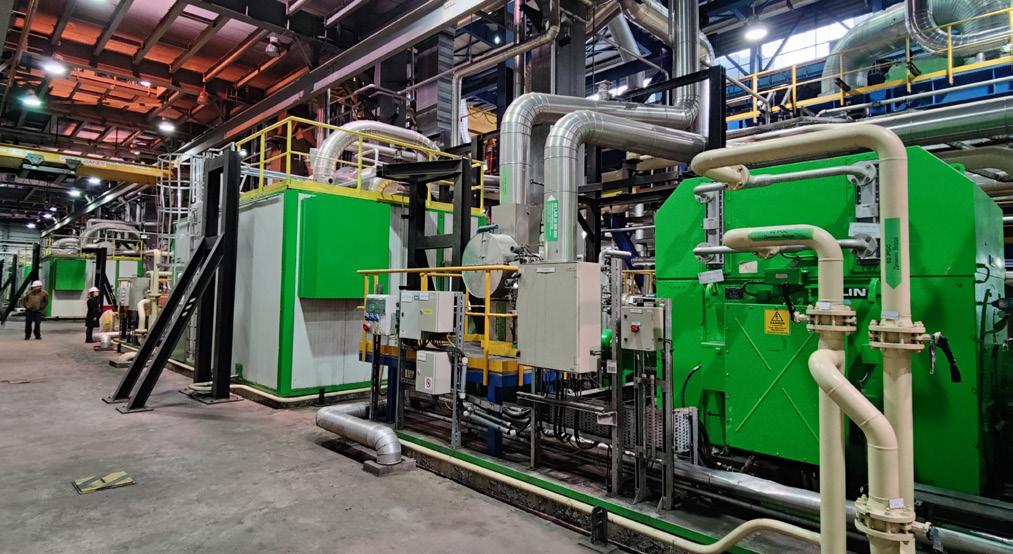
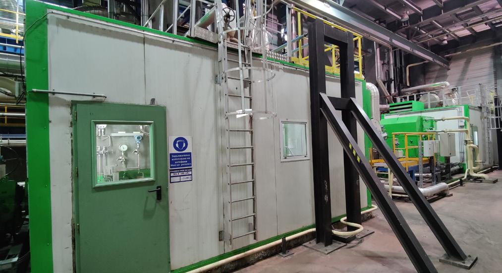
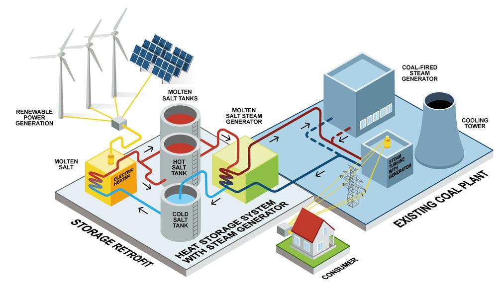
of the existing infrastructure, thereby securing the long-term viability of the asset while continuing to deliver reliable, clean energy to Bulgarian consumers to decades to come.
Conclusion
Aalborg CSP believes that there will be a breakthrough for this technology in Europe within a few years. The company is convinced that many owners of coal-fired power plants will see the benefits of using Power-to-Salt technology once the project economics and opportunities to repurpose fossil-based energy assets become clear, enabling a future security of supply based on renewable energy.
Figure 3 Most of the infrastructure at the coal-fired power plant can be reused when Aalborg CSP converts them into energy storage facilities.
Figure 4 . It is ideal to reuse coal-fired power plants for storing renewable energy instead of demolishing them and building new energy storage facilities from scratch.
Figure 5 . Aalborg CSP uses most of the existing infrastructure when converting coal-fired power plants into energy storage facilities.

GLOBAL NEWS
Peel Ports Clydeport welcomes record wind turbine haul
Peel Ports Clydeport has welcomed its largest ever turbines to a key facility for the renewable energy sector following a recent £3 million investment in infrastructure.
King George V Dock in Glasgow handled six wind turbines and their 80.5 m long blades – the biggest ever at the site owned by the UK’s second largest port operator.
The arrival of the components would not have been possible without the port group’s recent development of a new egress road and supporting terminal infrastructure, which was designed to improve the movement of such project cargo through the port.
The turbines arrived on the BBC Raise vessel from China in August 2025 and has since been transported to a major wind farm project near Ayrshire.
The new road, which was completed in spring 2025, provides a more efficient route for oversized cargo to Scotland’s major road network. The manoeuvring space for large pieces of cargo was previously limited, restricting operational capability.
The investment follows a record year in 2024 for the facility in handling wind turbines, with over a thousand components processed that year. More than 100 turbines and 800 wind turbine components will also be processed at the site over the next 12 months.
King George V Dock’s deep-sea facility is equipped to accommodate the handling of large scale wind turbine components, allowing for efficient movement of vital equipment to and from wind farm sites.
Wind power development agreement signed in Québec
Québec Premier, François Legault; Gespe’gewa’gi
Mi’gmaq Nation Chiefs, Céline Cassivi, Scott Martin, and Roderick Larocque; Mi’gmawei Mawiomi Business Corp. (MMBC) General Manager, Fred Vicaire; Alliance de l’énergie de l’Est (Eastern Energy Alliance) President, Michel Lagacé and Hydro-Québec President and CEO, Claudine Bouchard, have announced the signing of a partnership agreement between the Mi’gmaq of Gespe’gewa’gi, MMBC shareholders, the Alliance de l’énergie de l’Est, and Hydro-Québec for the development of wind power on the territory of the Mi’gmaq of Gespe’gewa’gi, which corresponds to the Gaspésie and eastern Bas-Saint-Laurent. This area could supply up to 6000 MW of wind power over the next few years.
This agreement marks a new era for energy development in eastern Québec, the strategic hub for wind power in the province. In addition to the local communities on Gespe’gewa’gi territory, which will benefit from wind power development, Wolastoqiyik Wahsipekuk First Nation will also benefit from the partnership, as a member of the Alliance de l’énergie de l’Est.
MMBC, l’Alliance de l’énergie de l’Est, and Hydro-Québec, in collaboration with the communities of Gespeg, Gesgapegiag, and Listuguj, are launching a structured, joint process to assess social and environmental acceptability and to integrate First Nations knowledge and priorities into wind power development in the Bas-Saint-Laurent and Gaspésie regions.
SSE and Equinor finalise seabed lease to progress Dogger Bank D
SSE and Equinor have finalised a seabed lease with The Crown Estate to progress the Dogger Bank D offshore wind project.
This marks the latest important milestone in the development of a proposed fourth phase of the world’s largest offshore wind farm, the 3.6 GW Dogger Bank wind farm, currently in construction off the coast of England in the North Sea.
The lease allows Dogger Bank D’s 50:50 joint venture shareholders, SSE Renewables and Equinor, to maximise the
potential renewable electricity generation capacity from the eastern portion of the existing Dogger Bank C seabed lease area, located around 210 km off the Yorkshire coast.
Delivery of Dogger Bank D is subject to it securing a Development Consent Order as well as a final investment decision by partners SSE Renewables and Equinor.
A fourth phase has the future potential to unlock an additional 1.5 GW in renewable electricity capacity at Dogger Bank for Britain’s energy system and would make the world’s biggest offshore wind farm even bigger.


GLOBAL NEWS
UKA secures environmental impact approval for agrivoltaic projects in Sicily
UKA Italia has navigated the environmental approval process for two of its agrivoltaics projects in Southern Italy. Both Pesce (42.73 MWp) and Capezzana (55.71 MWp) have received the environmental impact and landscape approval from Italy’s Ministry of Environment and Ministry of Culture, paving the way for final stages of project completion.
These projects, located in the municipality of Ramacca, Sicily, are planned to contribute significantly to Italy’s renewable energy landscape. The Pesce and Capezzana agrivoltaics projects are equipped with advanced solar modules mounted on tracking structures, ensuring optimal energy capture by elevating systems to a minimum height of 2.1 m. This design is complemented by Sicily’s exceptional solar irradiation, enabling an impressive energy generation exceeding 2100 kWh/kWp/y. Furthermore, their strategic proximity facilitates streamlined connectivity to the national grid via a shared pathway leading to a newly established TERNA 380/150/36 kV substation.
Diary dates
Solar & Storage Live Zürich 2025
16 – 17 September 2025
Zürich, Switzerland
www.terrapinn.com/exhibition/solar-storage-live-zurich
HUSUM Wind 2025
16 – 19 September 2025
Husum, Germany www.husumwind.com
Solar & Storage Live UK 2025
23 – 25 September 2025
Birmingham, the UK https://solarandstoragelive.com
Aura Power secures planning consent for Marsh Lane
Aura Power has secured planning consent for a 30 MW solar farm between Palgrave and Wortham in Mid Suffolk, following unanimous approval by the local planning committee in April 2025. The planning permission was subject to the signing of a legal agreement to provide measures to protect and support Skylark nesting areas, which has now been finalised and planning permission formally granted. The solar farm will be delivered in partnership with three local landowners.
Once operational, Marsh Lane solar farm will generate enough renewable electricity to power the equivalent of around 12 000 typical homes each year, saving an estimated 11 000 tpy of CO2
The project will also deliver a significant uplift in biodiversity, with extensive species-rich grassland, wildflower meadows, hedgerow planting, and habitat features designed to support birds and pollinators.
The company is progressing towards a grid connection date of September 2027, with construction scheduled to commence in early spring 2027.
Offshore Wind North East 2025 05 – 06 November 2025
Sunderland, the UK www.offshorewindne.com
Floating Offshore Wind 2025
12 – 13 November 2025
Aberdeen, Scotland www.renewableuk.com/events/floating-offshore-wind-2025/fow25
Energy Storage Summit 2026
24 – 25 February 2026
London, the UK https://storagesummit.solarenergyevents.com

HYDROPOWER
GLOBAL NEWS
Aker Solutions selected for hydropower upgrade in Norway
Aker Solutions will deliver the turbine and main mechanical systems for the Blåfalli Fjellhaugen hydropower project in Kvinnherad, developed by Sunnhordland Kraftlag.
Blåfalli Fjellhaugen will add 185 MW of regulated hydropower and generate an additional 70 GWh annually. Located within the existing Blådalsvassdraget system, the plant will increase total installed capacity in the watercourse to around 550 MW, with annual production reaching approximately 1.7 TWh.
Construction (expected to take four years) starts in September 2025, with LNS responsible for tunnelling and building the underground powerhouse. Konecranes will deliver the crane system, Lysaker & Thorrud the mechanical waterway components, and Hitachi the transformer and related systems.
Andritz Hydro supplies control and instrumentation systems for operation, monitoring, and power supply, as well as high-voltage systems at generator voltage level. Norconsult provides consultancy services for the planning and design of the power plant.
NCC to expand Bålforsen waterworks
NCC has been commissioned by Uniper to expand the Bålforsen hydropower plant in Lycksele, Sweden. The project encompasses the installation of a new turbine to increase the capacity and efficiency of the plant. The order value is approximately SEK 200 million.
NCC is responsible for the technical implementation of the expansion, from rock excavation and reinforcement to the installation of mechanical parts, such as hatches and penstocks. NCC has been conducting preparatory work at the hydropower plant since autumn 2024. Now, NCC has also been commissioned to install a new turbine and upgrade the existing turbines to improve the flow of water in the river, increase electricity generation, and enable the delivery of more system services.
Once the expansion has been completed, Bålforsen will produce 506 GWh/y, equivalent to the electricity needs of approximately 25 000 homes.
The project is scheduled to be completed in autumn 2027. The order value is approximately SEK 200 million and the order will be registered in the NCC Infrastructure business area in 3Q25.
EDP completes disposal of two hydropower plants in Brazil
EDP, S.A., through its fully owned subsidiary EDP –Energias do Brasil S.A. (EDP Brasil), has completed the sale agreement with Engie Brasil Energia S.A. for the total disposal of its stake (50%) in UHE Cachoeira Caldeirão and UHE Santo Antônio do Jari.
The transaction was concluded in line with the terms and conditions previously disclosed, having received, on this date, the total amount of R$1.1 billion (€0.19 billion, considering an exchange rate of 6.1 EUR/BRL), corresponding to an implicit Enterprise Value for 100% of R$ 2.9 billion (€0.5 billion).
This transaction reduces the weight of conventional generation and hydro exposure in Brazil, leading to a higher weight of regulated activities in this market.
THE RENEWABLES REWIND
> EDF and Ampeak Energy sign long-term agreement to optimise AW1 battery project
> Menter Môn Morlais awards Jones Bros £10 million contract
> HiTHIUM awarded energy storage contract by SEC
> Eco Wave Power awarded land use tender for Taiwan wave energy project
> ITM Power signs supply agreement with MorGen Energy
> Dutch government awards RWE grant for electrolyser project
Follow our website and social media pages for more updates, industry news, and technical articles. www.energyglobal.com

GEOTHERMAL
GLOBAL NEWS
Drilling of an exploratory geothermal well commences in Croatia
Drilling at the future geothermal power plant site of ENNA Geo in Babina Greda, Croatia, has commenced.
ENNA Geo, through its project company Geo Power Babina Greda, is developing a geothermal power plant project to generate electricity in Babina Greda with an installed capacity of 15 MWe. Drilling of an exploratory geothermal well has begun at the geothermal water field in Babina Greda. Over the next 110 days, the plan is to drill the well to a depth of 3850 m and conduct production testing, with an expected geothermal water flow of 110 l/sec. at a temperature of 170˚C. The investment in this exploratory well amounts to €11 million. In Babina Greda, plans include drilling an additional three wells and constructing the geothermal power plant, with a total planned investment of €100 million.
According to current findings, Babina Greda has two geothermal water reservoirs, offering potential for commercial electricity production and utilisation of the remaining thermal energy for industrial facilities and greenhouse cultivation of fruits and vegetables.
Odfjell Technology partners with Vercana on major geothermal energy project
Odfjell Technology, an integrated supplier of well services technology and engineering solutions, has signed a two-year contract with Vercana GmbH, Vulcan Group’s drilling subsidiary.
Odfjell Technology will provide tubular running services (TRS) to Vulcan Group’s Phase One Lionheart project in Germany, which aims to produce lithium sustainably by combining harnessed geothermal energy with critical mineral extraction.
Odfjell Technology’s drilling tool rental and TRS solutions will service the onshore geothermal project, located at Vulcan Group’s Phase One project site near Landau in the Upper Rhine Valley.
Germany’s geothermal energy market is expected to grow at an annual rate of 1.95% from 2025 – 2029.
The contract commenced in May 2025 and is being serviced by Odfjell Technology’s Netherlands hub.

will.powell@energyglobal.com / jessica.casey@energyglobal.com