| JULY/AUGUST 2025


| JULY/AUGUST 2025
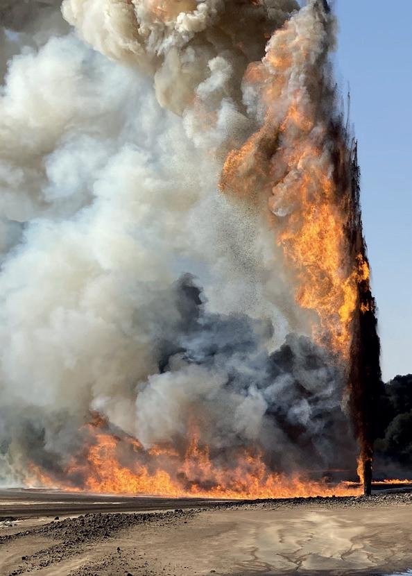
How compromised barriers, unexpected failures, and real-world field responses are shaping the future of well control.

www.worldpipelines.com

13 Precision pre-commissioning
Darrel Sookdeo, Vice President, Process Services, EnerMech, explores the role of pre-commissioning in Guyana’s gas-to-energy future.
05 Balancing growth and complexity
Stewart Maxwell, Technical Director at Aquaterra Energy, explains how the Asia-Pacific (APAC) region is balancing unmatched growth and complexity with the energy transition.
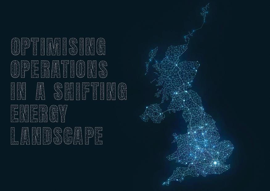
08 Optimising operations in a shifting energy landscape
Brendan O’Leary, Regional Manager, UK, Europe, Africa, Australasia, and Japan, WWT, discusses how to effectively optimise operations in a shifting energy landscape with reference to the UK.
Wild Well Control’s latest feature highlights the critical role of barrier integrity and the far-reaching consequences of well control failures. The front cover image captures an offset well impacted by a nearby well’s compromised integrity, demonstrating how unseen issues can escalate into field-wide emergencies. This real-world event underscores the need for proactive intervention and comprehensive
assessment.


17 Tackling well integrity early
Jace Larrison, Vice President – Well Control Engineering, UIS, and Training, Wild Well Control, USA, examines well integrity and the implications on well control events.
21 Easy button for H2S removal
Jordan Flaniken, Managing Director of Adsorbents, Merichem Technologies, discusses the opportunity for oil and gas production companies to address contaminant removal with ‘easy button’ solutions.
25 Paving the way for CCS
Garry Stephen, Oil States, UK and Asia, discusses how field-proven oil and gas technologies can pave the way forward for carbon capture and storage (CCS).
29 Developing technology in the offshore sector
Calum Dey, Engineering Manager, Decom Engineering, details the development of new technologies designed to meet unique challenges of cutting tasks in challenging environments.
32 Navigating uncertainty
Alan Quirke, Vice President of Well Intervention & Integrity, Expro, discusses the strategic role of well intervention and well integrity management in a capital-disciplined, socially conscious energy supply era.

36 Making strides in subsurface imaging in complex environments
Nick Tranter, STRYDE, analyses new technologies seeking to address the increasing requirements of oil and gas companies to acquire high-resolution 3D seismic data in complex, high-stakes environments.
39 Icing on the cake
Joel Shaw, Silverwell Energy, USA, examines how surface-controlled gas lift systems will play a greater role in maximising the potential of gas-lifted wells while minimising environmental impact and operational costs.


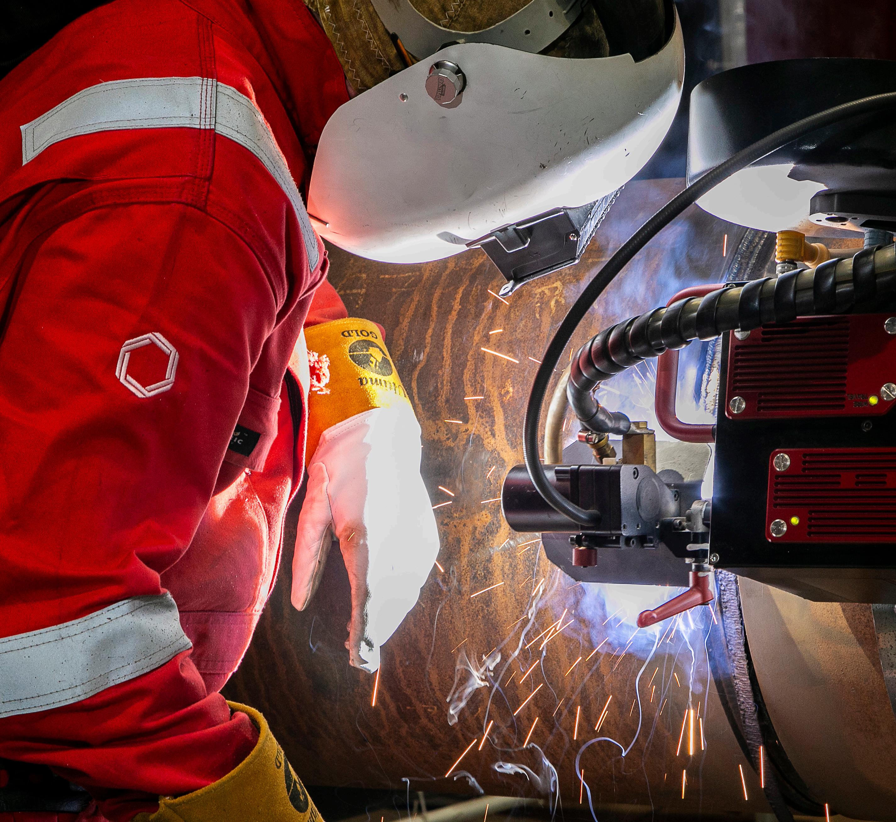
Across energy and critical infrastructure, we bring expertise where complexity is highest, partnering with globally local teams and leveraging unrivalled proprietary technologies. Like the M-500 Single Torch External Welding System, seamlessly integrated with Data 360 our cloud-based digital platform that analyses, and visualises your project performance data in real time. We move projects forward, no matter the challenge. We’re here to partner on how our specialist welding and coating solutions can help you power tomorrow.


SLB has announced that it has closed its previously announced acquisition of ChampionX Corporation. Under the terms of the agreement, ChampionX shareholders received 0.735 shares of SLB common stock in exchange for each ChampionX share.
“This acquisition comes at a pivotal time in the industry as our customers increasingly prioritise advancements in production to maximise recovery of oil and gas,” said Olivier Le Peuch, Chief Executive Officer of SLB. “This move expands SLB’s presence in this important, less cyclical, and growing market that aligns closely with our returns-focused, capital-light core growth strategy. It extends our capability to provide integrated production solutions and provides another platform for accelerating digital adoption, optimising production and reducing total cost of ownership for our customers.”
Perenco has announced the completion of the acquisition of the Greater Angostura producing oil and gas assets and associated production facilities from Woodside Energy in Trinidad and Tobago. The finalisation of the deal, combined with Perenco’s existing operation of the Teak, Samaan, and Poui (TSP) and Cashima, Amherstia, Flamboyant, and Immortelle (CAFI) fields, aligns Perenco as a major oil and gas producer in country.
Following this acquisition Perenco’s operations in Trinidad and Tobago will have a gross gas production base of more than 500 million ft3/d as well as a gross oil production of more than 10 000 bpd, that can both benefit from significant operational synergies, boost value and enable further investment.
Vår Energi ASA has entered into a collaboration agreement with TechnipFMC Norge AS for delivery of subsea projects utilising its integrated commercial model for engineering, procurement, construction, and installation. The agreement pertains to future subsea developments in the Gjøa area in the North Sea.
The Gjøa Nord, Cerisa and Ofelia discoveries are estimated to contain up to a total of 110 million boe gross. If the licence partners decide to proceed, the plan is to coordinate the three developments. This will realise synergies in procurement, engineering, drilling, installation and project follow-up. An investment decision is planned in 2026.
Viridien, in collaboration with joint venture partners, TGS and Axxis Multi-client AS, has announced its successful completion of the final imaging of OMEGA Merge, to deliver a single, seamless and unified high-quality dataset across the Heimdal Terrace, Utsira, and Sleipner Ocean Bottom Node (OBN) multi-client surveys.
McDermott has been awarded a sizeable offshore transportation and installation contract by BRAVA Energia, the most diversified independent oil and gas company in Brazil, for the PapaTerra field in the Campos Basin and the Atlanta field in Block BS-4 within the Santos Basin, both offshore Brazil. Under the contract scope, McDermott will execute the transportation and installation of flexible pipelines, umbilicals, and associated subsea equipment for two new wells at the Papa-Terra field and two new wells for the Atlanta Phase 2 development. The scope also includes pre-commissioning and onshore base support services.
Monumental Energy Corp. has announced its progress on the second workover at the Copper Moki-1 (CM-1) well in the Taranaki Basin, New Zealand.
Seatrium Ltd has announced the impending delivery of the first of a series of turnkey FPSOs, to Brazil’s Petrobras.
Expro has been awarded a three year contract by Woodside Energy, supporting the Trion deepwater oil and gas development, offshore Mexico.
Subsea7 has been awarded an engineering, procurement, commissioning and installation contract, offshore Egypt.
bp has signed an MoU with Libya’s NOC to evaluate redevelopment opportunities in the mature giant Sarir and Messla oilfields in Libya’s Sirte basin.
Shelf Drilling has been awarded a three year contract in India with ONGC.
Dräger Marine & Offshore will support the UK’s first offshore CO2 injection.
2 - 5 September 2025
SPE Offshore Europe Aberdeen, UK
https://www.offshore-europe.co.uk/ 9 - 12 September 2025
Gastech Exhibition & Conference Milan, Italy
https://www.gastechevent.com/visit/ visitor-registration/

Editorial
Managing Editor: James Little james.little@oilfieldtechnology.com
Editorial Assistant: Alfred Hamer alfred.hamer@oilfieldtechnology.com
Editorial Assistant: Emilie Grant emilie.grant@oilfieldtechnology.com
Design
Production Designer: Iona MacLeod iona.macleod@oilfieldtechnology.com
Production Manager: Kyla Waller kyla.waller@oilfieldtechnology.com
Sales
Sales Director: Rod Hardy rod.hardy@oilfieldtechnology.com
Sales Manager: Chris Lethbridge chris.lethbridge@oilfieldtechnology.com
Sales Executive: Daniel Farr daniel.farr@oilfieldtechnology.com
Events
Head of Events: Louise Cameron louise.cameron@oilfieldtechnology.com
Events Coordinator: Chloe Lelliott chloe.lelliott@oilfieldtechnology.com
Digital Events Coordinator: Merili Jurivete merili.jurivete@oilfieldtechnology.com
Junior Video Assistant: Amélie Meury-Cashman amelie.meury-cashman@oilfieldtechnology.com
Digital
Digital Content Coordinator: Kristian Ilasko kristian.ilasko@oilfieldtechnology.com
Digital Administrator: Nicole Harman-Smith nicole.harman-smith@oilfieldtechnology.com
Administration
Administration Manager: Laura White laura.white@oilfieldtechnology.com
Reprints: reprints@oilfieldtechnology.com
Palladian Publications Ltd,
15 South Street, Farnham, Surrey GU9 7QU, UK Tel: +44 (0) 1252 718 999 Website: www.oilfieldtechnology.com
Elizabeth Corner, Senior Editor elizabeth.corner@oilfieldtechnology.com
The keynote article for this issue, written by Stewart Maxwell, Technical Director at Aquaterra Energy, outlines the tightrope that the Asia-Pacific (APAC) region is walking as it attempts to balance growth with decarbonisation. APAC is experiencing surging energy demand, while being one of the world’s biggest carbon emitting regions (APAC will account for 50% of global energy demand, and 60% of emissions, by 2050).1 The challenge for APAC nations is to meet increasing demand while staying on track with global decarbonisation goals, and it’s a diverse region, so there is no ‘one size fits all’ solution. All of this means it has become an interesting testing ground for innovative, tailored solutions. Maxwell writes that, as energy demand continues to rise across APAC, upstream investment is surging to keep pace. The region is expected to invest an estimated US$3.3 trillion into power generation over the next decade, with oil and gas maintaining a vital share of the mix, particularly in China, India, and Southeast Asia (where LNG demand is booming).

But with the most accessible reserves already tapped, operators must work on unlocking smaller, and geographically challenging fields. Increasingly, in place of traditional infrastructure for E&P projects, there is growing reliance on fit-for-purpose, modular technologies designed to unlock value from previously uneconomic assets. These include conductor-supported platforms like Sea Swift (from Aquaterra), which can be installed directly from jack-up rigs.
Subsea drilling from jack-up rigs, a technique well established in other regions, is beginning to gain traction in markets such as China and Japan. It offers access to shallow-water and near-shore resources without extensive subsea infrastructure, helping to minimise environmental impact. Bohai Bay, China’s largest offshore oil-producing area, has shallow waters comparable in scale to the North Sea. Conventional semi-submersible platforms are not practical here, so modular solutions come into their own. By embracing smarter and smaller scale technologies, APAC operators are rethinking how offshore development can be more economically viable in the decade ahead.
Carbon capture and storage (CCS) is often billed as a secret weapon when it comes to decarbonising legacy assets and future-proofing infrastructure. Since 2000, emissions in APAC have risen by 151%, and one of the most promising ways to address this lies in repurposing the region’s ageing oil and gas fields.2 With over 200 offshore fields in Southeast Asia expected to cease production by 2030, these assets represent a ready-made opportunity for CCS deployment.
In Malaysia, Petronas and ExxonMobil are collaborating to unlock the country’s substantial 46 trillion ft3 of potential CO2 storage capacity in depleted offshore gas reservoirs. Indonesia has approved a series of CCS projects involving bp, INPEX, and Repsol. Yet while the commercial and regulatory groundwork for CCS is advancing, technical challenges remain, particularly around legacy well integrity. Read the full keynote article (p. 5) to find out how repurposed wells might safely and securely store CO2 long term.
The region’s most successful projects are being shaped through strategic collaboration, with a growing wave of JVs and long-term partnerships. Petronas is leading the charge, teaming up with Eni to form a Southeast Asian energy major, working with Woodside on long-term LNG supply deals, collaborating with Baker Hughes, and joining forces with TotalEnergies to invest in regional renewables. APAC’s energy transformation will depend on how effectively stakeholders can work together to build new infrastructure that is flexible and future-ready.
1. https://www.woodmac.com/press-releases/2024-press-releases/asia-pacific---energy-transition-outlook/ 2. https://assets.bbhub.io/professional/sites/24/Asia-Pacifics-energy-transition-outlook_FINAL.pdf

Stewart Maxwell, Technical Director at Aquaterra Energy, explains how the Asia-Pacific (APAC) region is balancing unmatched growth and complexity with the energy transition.
In the Asia-Pacific (APAC) region, rapid population growth, industrial expansion, and economic development have propelled energy demand to unprecedented levels, with the region projected to maintain a 50% share of global primary energy demand until 2050. But this growth is accompanied by a parallel challenge. Namely, how to meet surging demand while staying committed to decarbonisation, with APAC also
accounting for an expected 60% share of global carbon emissions until mid-century.
Matching the region’s growth is also its complexity, with huge variance in infrastructure, resources, and policy priorities between nations. Each country has unique challenges shaped by their geography, industrial structure, and regulatory landscape. This means there can’t be a ‘one size fits all’ approach. For example, while Indonesia is pursuing geothermal expansion, hydrogen development, and carbon capture, Vietnam has led the way on the rapid adoption of solar and wind energy.
For those operating in APAC, success means balancing growth with decarbonisation, while adapting, innovating, and working with the unique conditions of each country on the ground and across borders.
To meet rapidly growing demand, energy production across APAC is expanding. Oil and gas continues to play a crucial role, with LNG demand surging – particularly in China, India, and Southeast Asia – driving new investments in exploration and infrastructure. Over the next decade, APAC is expected to invest US$3.3 trillion in power generation, with fossil fuels maintaining a significant share.
At the same time, APAC’s easily accessible fossil fuel reserves are depleting, forcing the industry to turn to smaller, more complex resources. This demands a departure from traditional methods, embracing flexible and modular technologies like conductor-supported platforms, advanced drilling systems, and enhanced riser designs that enable these previously untapped resources to be made technically and economically viable.
Take the shallow waters of Bohai Bay in the Gulf of China, an area comparable to the North Sea in scale and significance. As China’s first offshore oil-producing area, with predominantly shallow depths, conventional infrastructure like semi-submersibles are impractical for developments in the field. Instead, modular solutions such as the Sea Swift platform, which can be installed directly from jack-up rigs, offer an efficient and safe alternative. By reducing the need for heavy-lift vessels, these platforms lower costs and improve project timelines while maintaining rigorous safety standards.
In markets like China and Japan, other technologies such as subsea drilling from jack-up rigs are also gaining traction for this same reason. Although proven in other regions, they represent a new frontier for these countries, offering both operational efficiency and the potential to tap into previously economically infeasible fields, while reducing environmental impact.
With emissions rising 151% since 2000, the need for decarbonisation is also clear. Carbon capture and storage (CCS) is emerging as a critical piece of this puzzle, not only addressing emissions from existing assets, but also shaping the long-term viability of offshore energy. But, while momentum is building, each region must navigate its own regulatory and commercial realities, requiring tailored approaches.
With approximately 200 offshore fields in Southeast Asia expected to cease production by 2030, these could present an opportunity for repurposing as CCS – or even hydrogen –storage facilities.
Malaysia is already taking steps in this direction. Petronas has identified vast storage potential in depleted gas reservoirs offshore Peninsular Malaysia and Sarawak, with over 46 trillion ft3 available. To advance these opportunities, ExxonMobil and Petronas are working together to assess CO2 storage sites and establish viable commercial frameworks.
Similarly, Indonesia has vast offshore storage potential and the country has approved CCS projects involving bp, INPEX, and Repsol, signalling its readiness while also forging international relationships to accelerate deployment.
However, scaling up CCS presents several technical challenges, not least being ensuring the integrity of legacy well formations to prevent CO2 leakage. Advanced well intervention technologies, like Aquaterra Energy’s Recoverable Abandonment Frame are cost-effective solutions to support the efficient re-entry of these wells, to establish an environmental and pressure-retaining barrier, ensuring safe re-abandonment and readiness for their long-term viability for carbon storage.
Equally important is ensuring that once CO2 is stored, it remains securely in place, particularly in a region which is known for being geologically active. Cutting-edge monitoring technologies can provide continuous, remote oversight of storage sites post-injection, detecting potential leaks or seismic activity throughout the lifecycle of a project. These innovations offer comprehensive, long-term assurances that stored carbon remains contained.
By leveraging these technologies, operators across APAC can not only reduce costs but also accelerate offshore CCS development. With greater confidence in carbon security, countries such as Indonesia and Malaysia can transform
depleted oil and gas formations and saline aquifers into reliable CCS storage sites, driving the region toward a lowcarbon future.
The APAC region’s diversity extends beyond geography to include unique regulatory environments and priorities. A unifying theme, however, is the growing emphasis on local content. For instance, Indonesia has introduced an update to PTK 007 which outlines how local companies are to be given preferential treatment during procurement activities, while in China, local sourcing is critical, even if not explicitly legislated.
Foreign companies navigating these markets must do more than introduce advanced technologies; they must invest in local partnerships, transfer knowledge, and build regional capabilities. By aligning global expertise with local insights, they can empower local content to propel APAC’s low-carbon future. This ensures solutions that are not only technically innovative but also culturally and economically resonant. Such an approach strengthens trust and positions international companies as key contributors to both regional progress and national aspirations.
APAC’s offshore energy journey is fundamentally a collaborative endeavour. As the region’s energy demand continues to surge, its leaders face the dual challenge of meeting immediate needs while laying the groundwork for sustainable growth that meets global climate goals. Through technologies like reduced steel platforms and offshore CCS, the region is bridging operational challenges with its
decarbonisation goals. At the same time, prioritising local partnerships will underscore the importance of shared progress.
This balancing act – between growth and sustainability, global expertise, and local insight – defines APAC’s energy transformation. By embracing innovation and collaboration, the region is charting a course that not only addresses its energy demands but also sets a global benchmark for sustainable development.
Stewart joined Aquaterra Energy as Technical Director in May 2013. In this capacity, he spearheads technical innovations across all facets of the business, encompassing wells and riser solutions, offshore analysis, the flagship offshore platform Sea Swift, offshore wind, hydrogen, and offshore CCS.
With a BEng in Mechanical Engineering from the University of Aberdeen and over 30 years of experience in the energy industry, Stewart has held positions in both Asia Pacific and the UK throughout his career. His expertise spans analysis, design, engineering, and installation of riser and conductor systems (shallow and deep water), as well as minimum facilities platforms, bespoke offshore engineering, and offshore problem solving.
Before joining Aquaterra Energy, Stewart spent 13 years with the Acteon Group of companies, in various positions including Regional Director – Asia Pacific and Global Manager – Conductor Systems. He has also worked for several operating companies, as well as establishing his own engineering consultancy in riser and conductor analysis, well integrity, and project management.


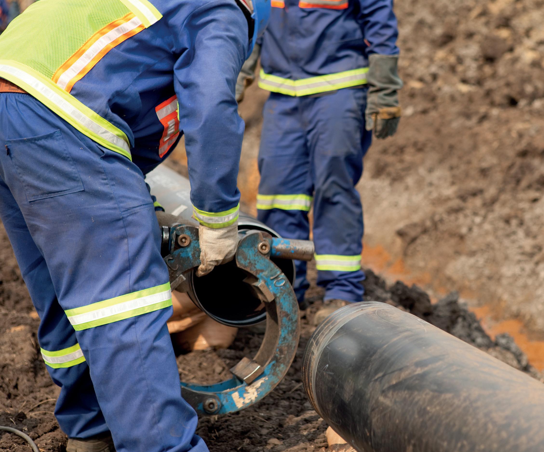
Brendan O’Leary, Regional Manager, UK, Europe, Africa, Australasia, and Japan, WWT, discusses how to effectively optimise operations in a shifting energy landscape with reference to the UK.
Refining operations is no longer optional. The oil and gas sector is evolving at a breakneck pace. For professionals in drilling and completions, especially in the UK, the mission is clear: survival through operational excellence. Traditional cyclical fluctuations have sharpened into structural upheavals. Political mandates, cost pressures, and the decarbonisation agenda are fundamentally altering market dynamics.
Consider Norway: its mature industry thrives due to the cohesive national support it receives. In Aberdeen, however, operators and service providers often feel isolated, without a unified industrial backbone. When times are good, there’s a tendency to outsource work, leaving UK skills and infrastructure on precarious footing. But stepping aside is not an option: we must continue pushing boundaries or face irrelevance.
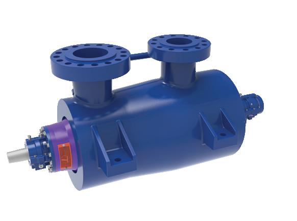
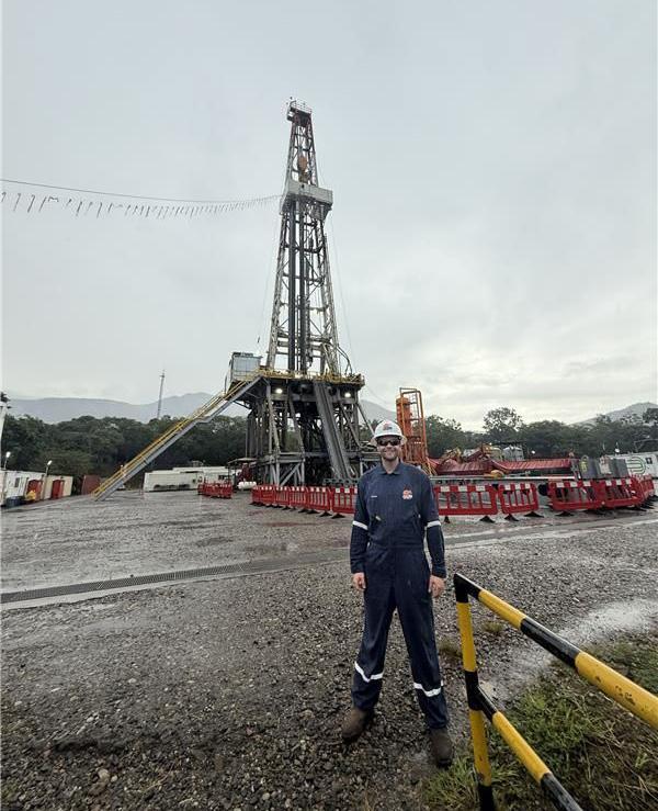
Thankfully, the UK remains a recognised leader in advanced drilling technology, but reputation alone will not suffice. We must apply innovation purposefully, deploying proven tools and smarter digital strategies to deliver value-driven, measurable optimisation. That is exactly what WWT has been doing: not chasing flashy new tech, but using software, refined procedures, and field-proven models to extract more value from every well. Our team recently travelled to South America to support key clients with our expertise in optimising well operations, ensuring that proven solutions are applied where they matter most (Figure 1).
From cycles to seismic change
Gone are the days when oilfield services could rely on predictable boom-bust cycles. The North Sea now grapples with declining production volumes and rising extraction costs, constrained further by environmental imperatives and complex geopolitics. UK operations don’t enjoy the same backing as their Norwegian counterparts, be it tax incentives, policy certainty, or research and development (R&D) grants. This fragmentation places extra burden on regional players.
In times of demand, subsea work is subcontracted abroad and when the market cools, the local supply chain bears the brunt. That lack of resilience hinges on one insight: our competitive edge must come from operational superiority, not cost alone. We pivot by delivering better results, faster, and more sustainably.
Turning digital tools into field gains
The past 30 years have introduced significant digital change, but not necessarily new digital technologies. What has evolved is the strategic application of better torqueand-drag modelling, advanced downhole telemetry, and optimised workflows. WWT doesn’t deploy tech to be trendy; it deploys it to solve known subsurface challenges.
Torque reduction and casing protection: real-world proof
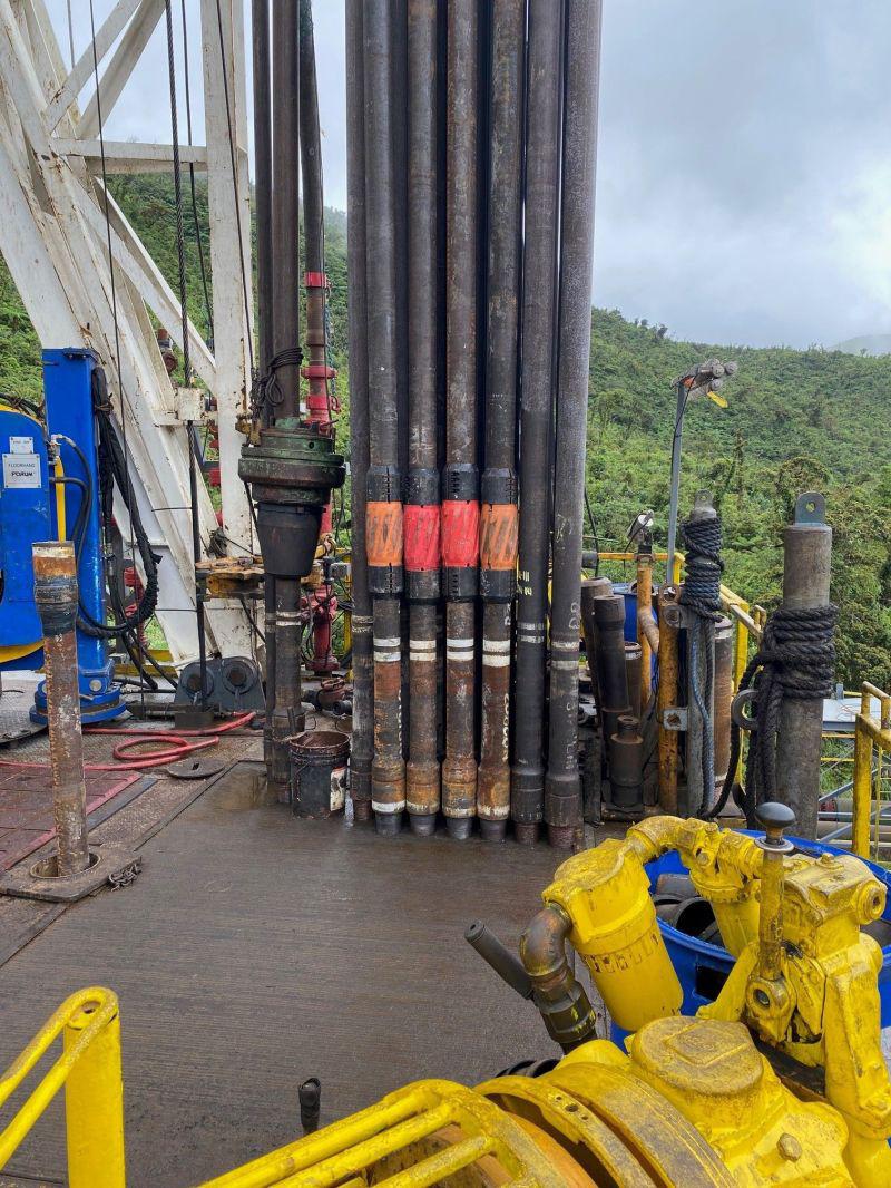
Non-rotating protectors (NRPs) (Figure 1) have delivered measurable benefits in European wells, and especially offshore UK basins:
Ì Offshore directional well (North Sea): running 282 SS3 model NRPs between 300 - 1620 m MD resulted in an 18% torque reduction, low casing wear, and strong model alignment with actual well performance.1
Ì ERD offshore campaign: in drilling a ~9.2 km ERD section, 300 SS3 model NRPs reduced torque by 32%, with real-time torque averaging 55 kNm versus 81 kNm predicted without NRPs.2
Ì Horizontal ERD success: SS model NRPs delivered a 40% decrease in torque and significant vibration reduction; cutting torque from 35 500 ft-lb to 20 000 ft-lb.3
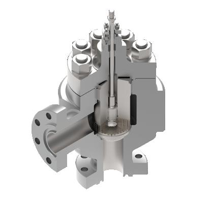
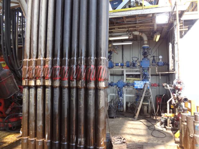
These numbers aren’t theoretical; they are precise, repeatable gains driven through friction reduction and vibration damping. The impact: faster drilling, reduced non-productive time, lower risk of torque-related failure, and improved casing integrity (Figure 2).
Diversification is key
When home markets slow, WWT’s integrated global presence ensures stability. International deployments in the Middle East, the US, continental Europe, Africa, and Asia keep our technical edge sharp and our economics healthy.
Ì In the Middle East, SS3 model NRPs have cut torque by 26 - 37% in ERD builds; one S-shaped well recorded a 30% torque drop.4
Ì In the US Lower 48 states, NRPs supported eight of the ten longest laterals – showing 12 - 16% torque reduction while maintaining high rates of penetration.5
Ì Alaska’s extended-reach liner runs saw smoother deployment and drag optimisation by outfitting liner strings with NRPs.6
These international wins feed back into the North Sea toolkit. We’ve refined best practices tool spacing, casing strategies, that directly translate back into the UK market, reinforcing our local value.
New horizons for old skills
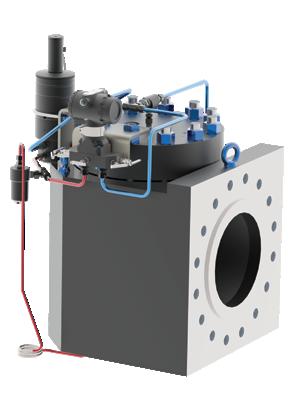
Transition matters. That’s why WWT is proactively engaged in geothermal markets, leveraging the company’s worldwide deepwell abilities in a new energy context (Figure 3).
The company’s geothermal tools already mirror oilfield NRPs and tractors in multi-kilometre lateral runs. High torque and vibration remain major challenges. Our NRPs have proven
casing protection in geothermal wells – over 500 000 drill-pipe revolutions sustained with HT3 500 protectors in the US and CRA casing protected in Asia.
These aren’t diversions; they are convergent applications. Every hour saved, every trip avoided, and every ft-lb of friction eliminated adds up. For geothermal operators, this means fewer failures, faster ramp-up, and lower carbon intensity – all while reusing existing supply chains and skill sets.
Low-hanging fruit for low-carbon impact
Sustainability is not only about alternative energy – it’s also about doing more with less. Every ft-lb or kNm of torque reduced saves energy. Every avoided trip, vibration event, or casing repair avoids carbon emissions – and keeps wells on schedule and budget (Figure 4).
Our approach delivers measured results:
Ì 40% torque reductions equate to substantially lower rig energy consumption and emissions.
Ì NRPs extend casing and drill-pipe life – reducing the carbon intensity tied to equipment manufacturing and transportation.
Ì Smarter planning and digital modelling prevent over-sizing and under utilisation of assets – cutting waste.
The results are quantifiable: lower rig time, fewer failures, less rework, and a smaller emissions footprint.
The survival imperative
The challenge for UK oilfield professionals is stark: either optimisation or obsolescence.. This isn’t about holding ground – it’s about evolutionary transformation. We have seen the proof: torque reductions up to 40%, casing protection proven across 30+ years, and global demand confirming the value of performance-first solutions.
At a time when national frameworks lag, operational excellence remains our strongest asset. WWT don’t wait for policy alignment or market rebound. Instead, they act swiftly, systematically, and informed by data.
To peers in Aberdeen and across the UK: redouble your focus on smart deployment – not flashy tools. Leverage proven field tech, support it with rigorous modelling, measure relentlessly, and iterate. Combine this with digital tooling, data driven insights, and a commitment to efficiency, and you’ll emerge not just intact – but leading.
The truth is simple: in this industry, survival favours the optimised.
1. https://www.wwtco.com/media/kcsmvazh/wwt-nrp-case-historydirectional-europe-11900.pdf
2. https://www.wwtco.com/media/ylejl5sx/wwt-nrp-case-historyerd-offshore-europe-12260.pdf
3. wwt-nrp-case-history-horizontal-europe-6340.pdf
4. wwt-nrp-case-history-directional-middle-east-10433.pdf
5. WWT Case History - Horizontal - North America - 5469
6. https://www.wwtco.com/media/5edmknsl/wwt-nrp-case-historyerd-alaska-11949.pdf
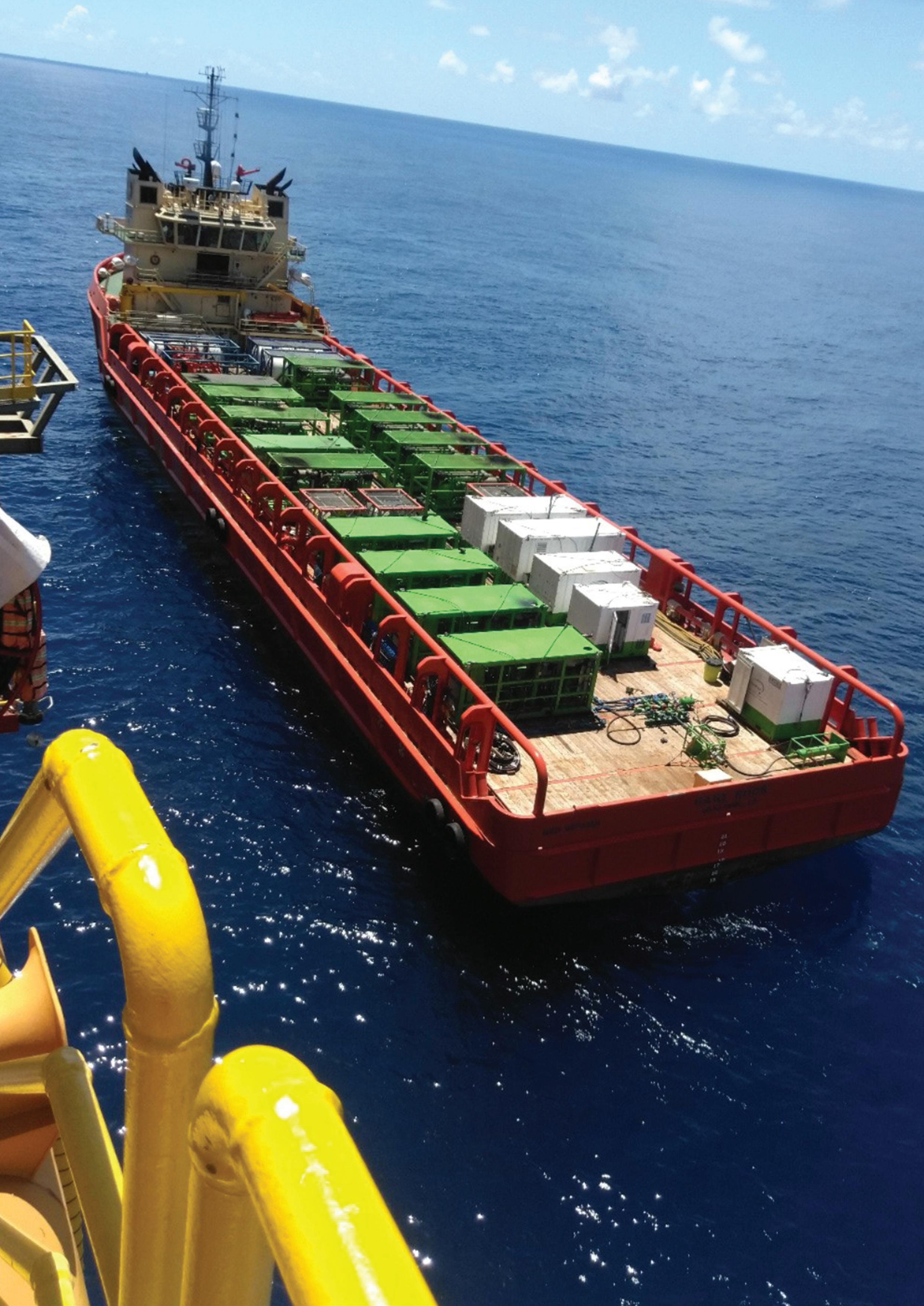
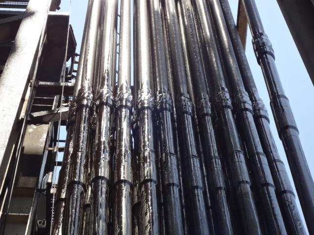
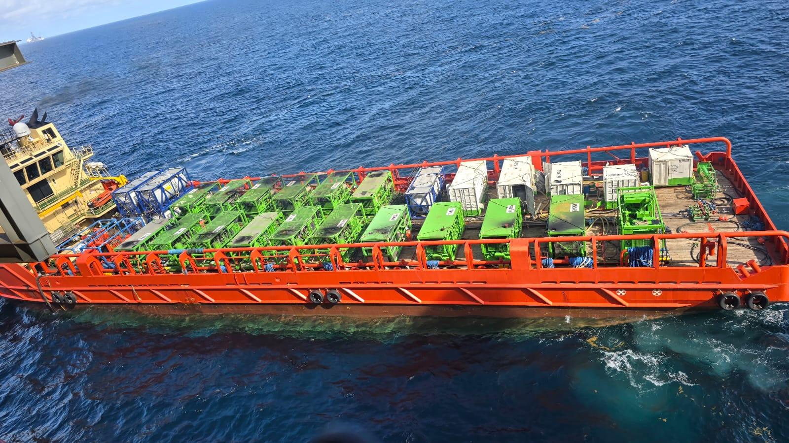
Figure 1. EnerMech has a proven track record in complex offshore and subsea commissioning campaigns.
Darrel Sookdeo, Vice President, Process Services, EnerMech, explores the role of pre-commissioning in Guyana’s Gas-to-Energy future.
Guyana’s ambitious Gas-to-Energy (GtE) initiative represents a significant leap forward in the nation’s energy security and economic transformation.
Central to this effort was the repurposing of the offshore Stabroek Block’s Liza Phase 1 and 2 Projects, as a critical offshore hub enabling
the redirection of natural gas from deepwater reservoirs to a new integrated natural gas liquid (NGL) plant and a 300 MW combined cycle power plant via a 200 km subsea pipeline.
At the heart of this transition was the need for precise, safe and expertly managed pre-commissioning of systems across two FPSO vessels and gas export infrastructure.
With a proven track record in complex offshore and subsea commissioning campaigns, EnerMech was selected to deliver a turnkey pre-commissioning solution. The scope was technically intensive and logistically demanding, yet strategically vital to ensure that the gas export pathway, from the FPSOs to the shores of the Demerara River, was ready to flow safely and reliably, marking the next phase in Guyana’s energy evolution.
The significance of this project cannot be overstated. The Gas-to-Energy programme is a high-profile partnership with the Government of Guyana, intended to reduce domestic electricity costs and lower carbon intensity by switching from imported fuel oil to cleaner-burning natural gas. For EnerMech, the project represented a chance to demonstrate a long-term commitment to Guyana by delivering excellence in a politically sensitive, high-visibility programme that will shape the country’s energy future.
By ensuring the gas export infrastructure on the FPSOs was ready for handover, EnerMech played a pivotal role in unlocking a project that will power industries, reduce household energy bills and accelerate Guyana’s journey toward energy self-sufficiency.
EnerMech’s pre-commissioning work was multifaceted. The included dewatering, line conditioning, air drying, nitrogen packing, and critical valve testing, works that are essential to prepare the gas export lines and associated systems for safe operation. These works were complemented by topsides piping construction, flange management, nitrogen, and leak testing services to ensure gas tightness from source to shore.
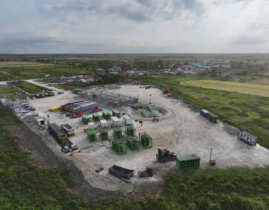
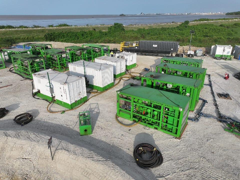
A major innovation was the use of low-pressure airdrying techniques and the implementation of dust bag receivers for pigging operations which were selected to reduce environmental impact and mechanical risk. The EnerMech Control of Work System was deployed to provide real-time procedural control and safe execution throughout the operation.
Dedicated mobile nitrogen and high-flow air units were mobilised, including one of the largest high-pressure nitrogen/air packages ever deployed in Guyana. These bespoke assets allowed EnerMech to meet the high technical demands of the project while adapting to the limited infrastructure and logistical restrictions of the region.
While the technical execution was complex, the physical environment made it even more challenging. The project was based on the west bank of the Demerara River – a region without the robust infrastructure found on the east bank, where most oil and gas activity in Guyana has traditionally been concentrated.
Transporting equipment to site was a formidable task. With the Harbour Bridge unable to handle loads over 20 t, heavy packages had to be barged across the river. Even this wasn’t straightforward: tide cycles dictated movement windows, and the west bank had no formal port facilities. Temporary landing zones were created, using mobile cranes and hired trucks to transfer critical gear from barge to jungle paths.

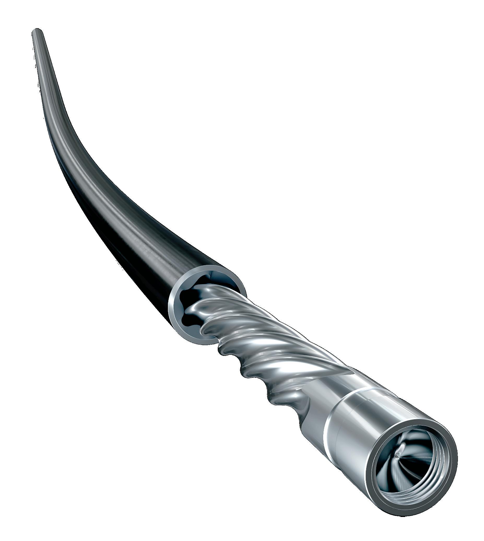
Abaco meets the demand to drill faster, deeper and farther— by creating advanced engineering designs and technologies that enhance power section performance and reliability. Field-proven innovations like OPTIFIT® stators and high temperature 350°- 400°F elastomers. Advances that have successfully powered thousands of runs in harsh drilling environments worldwide.
Explore Abacodrilling.com and learn how our power section innovation can improve performance in the challenging conditions you face downhole.

Access to the pipeline landfall site presented further issues. Located deep in a forested zone, the only access routes were undeveloped, prone to flooding and often impassable.
On top of that, accommodation and catering had to be arranged locally, as daily commuting was unrealistic. EnerMech scouted and leased accommodation in the nearby community, partnering with local vendors to support meals and logistics. The decision to integrate more Guyanese personnel and reduce expat reliance proved essential to operations and for strengthening ties with the local workforce and government stakeholders.
In such a sensitive and high-profile environment, risk mitigation was paramount. EnerMech identified and addressed a range of operational, environmental and community risks prior to mobilisation. Nitrogen venting, for instance, was conducted in remote, downwind locations with hard physical barriers in place to control exposure. For noise impacts near populated border areas, sound blankets and silencers were used in combination with continuous noise monitoring.
Wildlife hazards were another major concern, with the area home to over 50 species of snakes, as well as other reptiles, mammals, and amphibians. A full-time wildlife specialist was embedded with the team to ensure animal safety and compliance with environmental guidelines.
From a safety perspective, the project achieved its core KPIs: zero lost-time incidents (LTIs), zero environmental incidents, and zero instances of non-compliance. This was achieved through the deployment of site-based safety supervisors, a

strict Permit-to-Work system, a medical emergency response team and comprehensive site orientations. Security protocols were also enforced to manage personnel movement and asset integrity throughout the campaign.
The project also demanded real-time problem solving. To prevent overheating of equipment in the hot, humid Guyanese climate, the EnerMech team devised an auxiliary cooling system to counter this issue. The cooling system created a continuous misting loop around the compressors, significantly reducing radiator temperatures and preventing overheating.
This had a large positive impact on the operations, the result being reduced air spread downtime. The solution proved so effective that it has since been adopted as a bestpractice standard on other EnerMech projects, a clear example of how innovation born in adversity can drive long-term operational efficiency.
As Guyana advances its transition from oil export to integrated energy producer, projects like Gas-to-Energy – and partners like EnerMech – will be central to shaping what comes next. The successful pre-commissioning of Liza Phase 1 and 2 Projects for gas export represents what is possible when global expertise meets local opportunity, and when challenges are answered with precision, innovation and purpose.
EnerMech is proud to have contributed to this national milestone and remains committed to supporting Guyana’s energy journey, one project, one community and one breakthrough at a time.


Jace Larrison, Vice President –Well Control Engineering, UIS, and Training, Wild Well Control, USA, examines well integrity and the implications on well control events.
ell control personnel respond to a wide range of issues, many of which are directly related to well integrity. The general definition of well integrity refers to the loss of previously established wellbore barriers. This is typically caused by tubular failures within the wellbore and could also include surface equipment failures. In many of these events, issues within the wellbore may be
unknown or not clearly understood until the final piece falls into place, and the well begins to flow. These events prove to be extremely challenging due to the lack of access to the original wellbore (through some form of tubular failure) or the lack of understanding of the flowpath involved in the flowing system.
In many cases, an intervention on the well would have been substantially less complex if a proactive approach had been taken before the event occurred.
Tubular failures are among the most complex and challenging issues to address when a well is flowing in an uncontrolled state. This uncontrolled state typically occurs because the wellbore barrier (casing or tubing) has failed, and the reservoir pressure cannot be contained by an exposed formation post-failure. If this has occurred, this is referred to as an underground blowout (UGBO) or oftentimes termed as cross-flow. Hydrostatic pressure is the key to an effective kill as most are readily aware of. Depending on the location of the failure, establishing a kill can become increasingly more difficult in these UGBO cases.
In general terms, tubing and casing failures that are shallow have the potential to lead to broaching. Broaching is the term used when flow from the well exits to the surface outside of the wellbore casings. Depending on the severity of the flow, all access can be lost to the wellhead making a relief well (RW) the only viable option for intervention. If access is still feasible, shallow failures may offer the chance to establish a fluid column but typically require some manner of live well intervention to access the well below the exit point (via coiled tubing [CT] or snubbing).
Tubing and casing failures that are deeper generally limit the fluid column that can be established and thus limit the hydrostatic pressure available to generate a kill within the wellbore system. Many times, these situations have only been solved by mechanical barriers in combination with a fluid column. The configuration of the well and the flowpath will ultimately dictate the proper solution.
In order to use the above discussion in context, the following case history will be discussed. The following are some of the important points to note about the well prior to the final integrity failure.
Ì The surface casing was compromised near surface at +/- 164 ft.
Ì The production casing was compromised near surface at +/- 236 ft.
Ì The production tubing had a failure at +/- 383 ft.
Ì The production tubing had a packer set with a plug in the tubing at +/- 4102 ft.
Ì There were perforations within the production casing that had previously been squeezed with cement. The depths were +/- 1771 ft, 2362 ft, and 2559 ft.
Ì The reservoir for this particular well was at +/- 4170 ft.
Ì The well was not actively producing with the plug set in the packer for isolation.
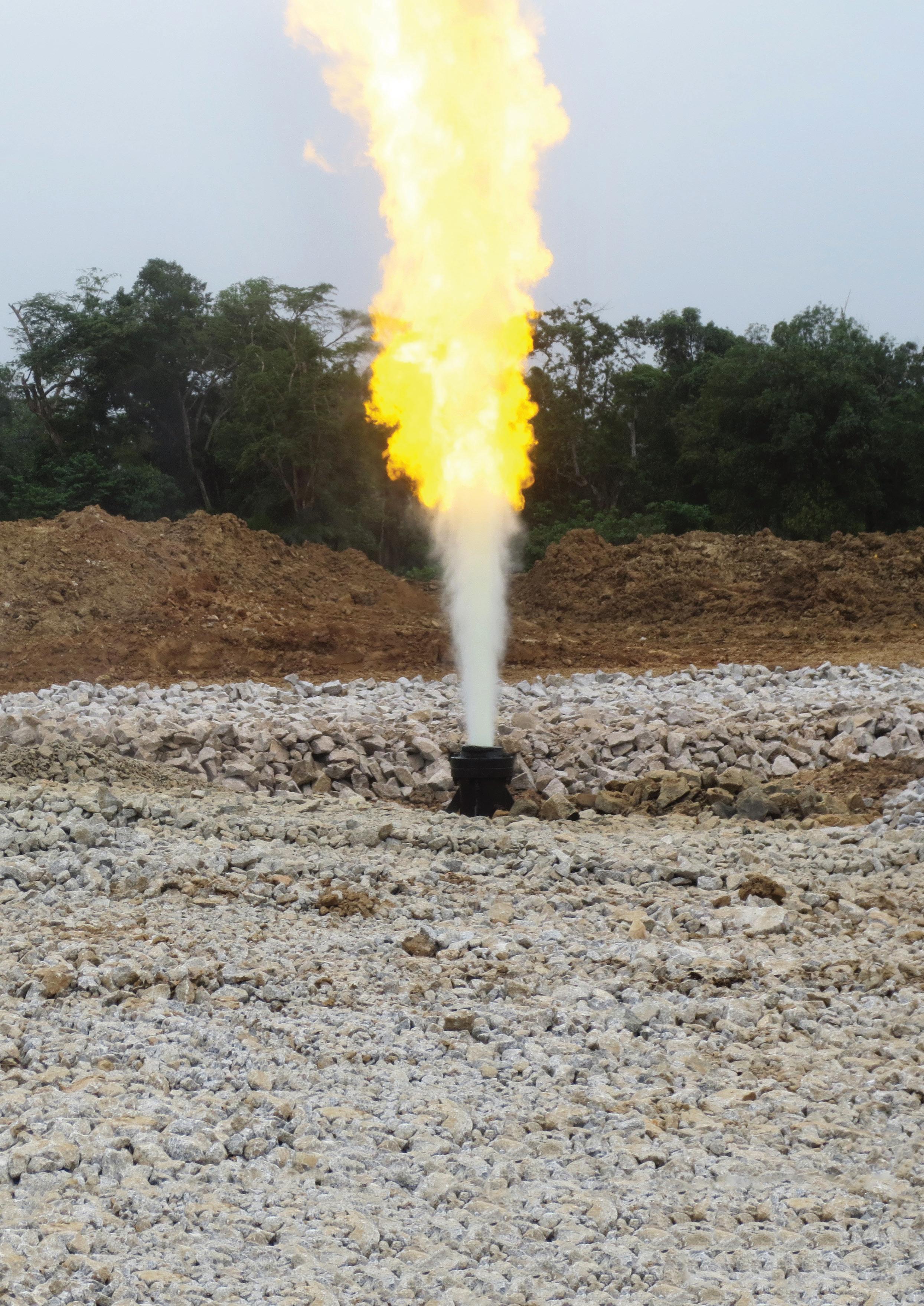
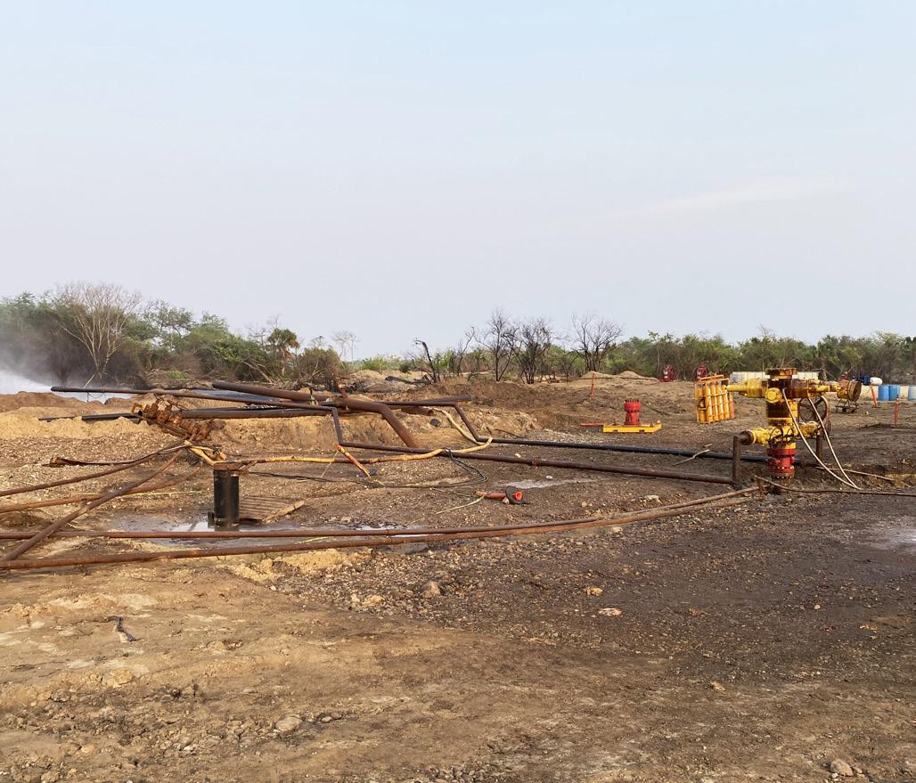
There was no flow associated with this well for years until flow was noted exiting around the well casing at surface. Figure 2 notes the wellbore diagram. The failure mechanism that caused the flow remained unknown for much of the intervention efforts as there were multiple possible flowpaths. Attempts were made to access the tubing string, but nothing was able to reach a depth deeper than +/- 2624 ft. Prior to the involvement of Wild Well Control (WWC), kill attempts were completed but these were unsuccessful. A large area around the wellhead was washed out from the ongoing flow exiting the well casing at the noted surface casing failure point above.
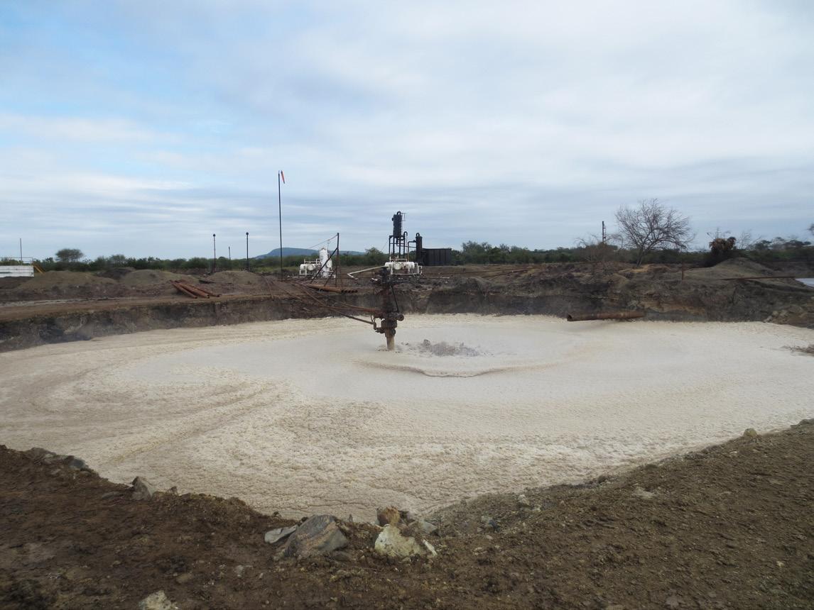
The area around the well was eventually washed out to the point that access to the wellhead was no longer possible. Typically, events with a shallow exit from the casing warrant some type of diversion in an effort to stop or limit the degradation of the surrounding area. In this case, diversion was initiated through the well production tree and lines installed via unconventional mechanisms. It was then proposed to fill in the large crater around the area once the predominant fluid flow was diverted and no longer exiting from the well casing. The crater was successfully filled in and compacted to allow access to the wellhead for personnel. Figure 3 shows the wellhead area prior to full diversion and re-filling.
With access to the well restored, the tubing which provided no real access to the well needed to be removed. With multiple integrity issues associated with the wellhead, a plan was developed to cut and remove the tubing spool – dropping the upper section of the tubing into the well. A capping stack (single BOP dressed with blind rams and a flow cross with valves) would then be installed in order to proceed to further intervention efforts using a snubbing unit. The tubing spool was successfully cut and removed, along with the remaining flange face, exposing the casing spool flange for the installation of the capping stack. The capping stack was landed and 6 in. diverting lines were installed on the flow cross and the blind rams were closed diverting the well flow to the nearby existing pit. Figure 4 notes the well after the tree was cut and removed, and the capping BOP was installed to divert the well flow in preparation for the snubbing operations.
A snubbing unit was installed, and the tubing string was successfully fished from the well allowing for further diagnostics to be completed via logs to determine the flow path. From the logs, it was determined that the primary flow path was inside of the production casing near the bottom of the well. The flow then exited the production casing at +/- 3280 ft and travelling up the annular space outside of the production casing to the exit in the surface casing. From this diagnostic programme and the recovery of the packer, it was deduced that failure of the packer allowed the initiation of the flow from the well through the previously failed casing strings. The well was finally secured by setting a packer on the snubbing work string below the failure point in the production casing. All flow from the well ceased. The well was then fully plugged and abandoned (P&A).
In summary, there were multiple issues with the wellbore integrity prior to the event. It was only after the packer failure occurred that the other issues were realised. This was an extensive intervention operation required to gain access to the well and ultimately stop the flow for P&A.
The subject wellbore was originally a dual completion design (two tubing strings landed in the tubing hanger). The well had been shut-in and had not produced for years. Approximately 10 years prior to the well control event, it had been determined that both tubing strings could no longer be accessed due to fish (previously set plug components) within the tubing. A bridge plug (BP) was set in each tubing string, and the pressure was bled to 0 psi.
The well control event initiated with the notation of flow from the casing spool outlet. The manual gate valve in place
on the tubing spool (C-section of the wellhead) was flowing freely into the well cellar. Upon excavation of the cellar, the casing valve on the casing spool (B-section) was also noted to be flowing. This discovery suggested that the production casing was very likely compromised.
During a review of the well history, it was noted that the intermediate casing string would not pressure test and had to be squeezed with cement. This brought forward immediate concerns about the pressure integrity of this casing. With the
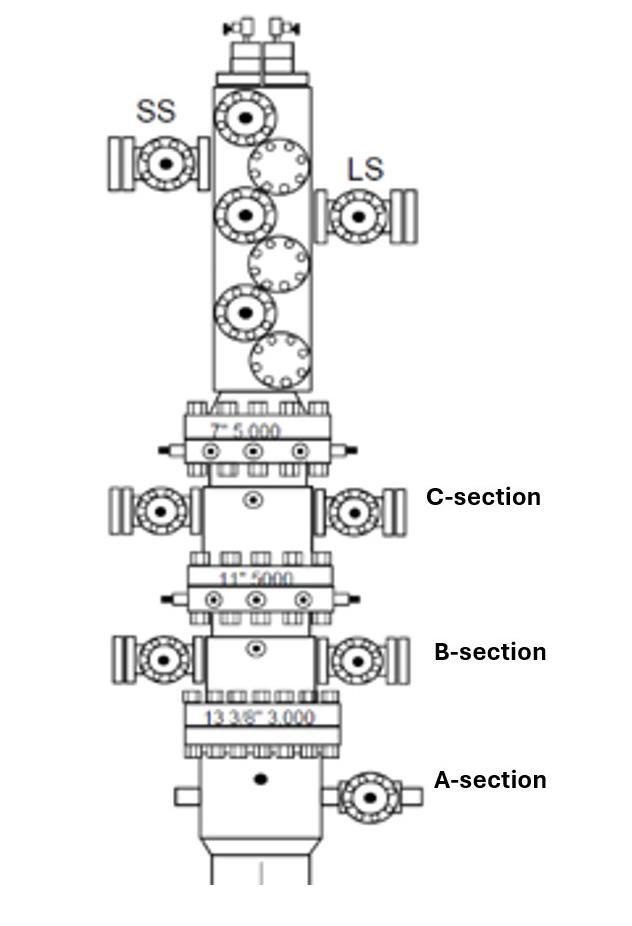
production casing string compromised and suspicion of issues already present within the intermediate casing, the initial plans for this intervention were to divert flow upon capping. Any shut-in could lead to flow to the surface casing shoe and then elsewhere outside of the wellbore system.
The water table in this area was extremely shallow, which would limit the depth of excavation that would be possible. The well flow subsequently caught fire, so this brought additional concerns related to the wellhead integrity. The top of cement (TOC) on the production casing was deep and thus would lead to a substantial length that the casing would drop if the entire wellhead was cut and removed. This casing drop would very likely be deeper than the water table and cause additional complications with any potential excavation for re-heading the well. In summary, the following points were derived for the planned intervention efforts:
Ì Total removal of the wellhead system was not a suitable approach due to the shallow water table.
h The A-section would be left in place for the pending diverting operations. Remember that flow was already present on the intermediate by production annulus. By cutting the casing spool, the production casing would be dropped, and all flow would be now from the intermediate casing at the A-section flange.
Ì Diverting the flow was the only control option given the fire and possible wellhead integrity issues.
Ì A substantial fishing job would be required to kill the well. With limited resources available in the area to execute this, a RW would be the final kill solution.
A significant amount of clearing and preparation was executed in order to prepare the well area for the direct
intervention efforts. A cut was made through the wellhead B-section with a WWC abrasive jet cutter to remove all the wellhead except the A-section. A capping BOP was installed on the original wellhead flange, and all flow was diverted to a nearby gas plant.
A RW was then successfully drilled and intersected with the flowing well just below the production packer on the long string (LS) tubing. The well flow ceased after a brief period even prior to the volume anticipated for the planned dynamic kill (DK). Cement plugs were pumped and tested, and the well was to undergo further P&A from the surface with a conventional rig system.
In summary, the previously noted issues with the casing and tubing strings added considerable complications to this event response. These ultimately led to the use of a RW for the final kill effort. It is not possible to fully confirm this, but the general suspicion was that the failure of the packer on the LS tubing is what led to the event. This suspicion was further supported based on the reaction of the flow after intersection of the RW.
Well integrity continues to have a lasting impact on well control events and how these events are resolved. Generally, the more well integrity issues that are present in a wellbore, the more complex the resolution becomes. The cost of these events is greatly increased once flow is present. Consequently, many of the lessons learned on this subject have been to tackle these integrity issues early, prior to escalation.


A podcast series for professionals in the downstream refining, petrochemical, and gas processing industries
EPISODE 6
Leakhena Swett, President, ILTA, and Jay Cruz, Senior Director of Government Affairs and Communications, ILTA, consider the importance of trade associations and industry collaborations.
EPISODE 7
Susan Bell, Senior Vice President within Commodity Markets – Oil, Rystad Energy, discusses the impact of trade wars on global oil demand and prices, in light of recent US trade tariffs.
EPISODE 8
In this special episode, a panel of experts from Johnson Matthey, A.P. Moller - Maersk, Honeywell, HIF Global and the Methanol Institute provide a clear analysis of the factors influencing e-fuel pricing, the economic challenges, and strategies for cost reduction.


EPISODE 9
Brandon Stambaugh, Owens Corning Director for Technical Services, discusses engineers’ demand for education and training to support three critical phases that affect the performance and longevity of insulating systems.

EPISODE 10
Lara Swett, Vice President of Technical & Safety Programs, American Fuel & Petrochemical Manufacturers (AFPM), explains how the downstream sector continues to improve its process safety record.
Listen and subscribe here
Jordan Flaniken, Managing Director of Adsorbents, Merichem Technologies, discusses the opportunity for oil and gas production companies to address contaminant removal with ‘easy button’ solutions.
xploration and Production (E&P) of oil and natural gas often involves high risk, high investment, and technologically intensive activities. If the industry’s activities aren’t complex enough, environmental concerns, product quality, and the protection of equipment require E&P companies to remove impurities such as hydrogen sulfide and mercaptans before the oil and gas is transported.
E&P operators need an easy button to simplify the hydrogen sulfide (H2S) and mercaptans removal step.
A range of treating systems using liquid and solid solutions and service technology companies are available for H2S and mercaptan removal, each with inherent advantages and disadvantages. The importance of understanding these technologies and how they address E&P requirements cannot be overstated. This knowledge is paramount when considering all operational factors, especially those that contribute to speed to market, maintenance concerns and costs, functionality of the equipment, and making operations more straightforward, all while ensuring the environment is protected, and safety is maintained.
H2S, a highly corrosive and poisonous gas, can be a significant nuisance to upstream production. This contaminant can be generated naturally or produced by technologies used during the E&P process.

Natural synthesis of H2S can happen in the reservoir due to microbial sulfate reduction (MSR) of sulfate-containing minerals and/or thermochemical sulfate reduction (TSR). Processing derived H2S production can happen when using E&P technologies such as steamassisted gravity drainage (SAGD) and hydraulic fracturing used in the production of oil sands and shale oil/gas.
H2S can manifest in all rig areas where drilling fluid and associated equipment are present, including the rig floor, substructure, shale shakers, mud cleaners, mud pit room, mud pump room, and well test equipment. Drilling and well control equipment not designed to mitigate H2S could be subject to structural integrity, impeding functionality and operations.
Upstream operators can anticipate H2S:
Ì Inherently in associated natural gas (‘sour gas’).
Ì During break out, also known as ‘run in the hole’, when the drill pipe has been completed, and bottom fluids are displaced to the surface.
Ì If a drill pipe is extracted from the well too quickly and fluids enter the wellbore.
Ì During the retrieval of core or fluid samples.
Ì During the flow test process when the well flow rate, pressure, and water level are monitored and recorded.
E&P operators are known to pay US$15+ million a year in operating costs to remove H2S, but some existing technologies being
used in production fields are inefficient, uneconomical, and in some cases, unsafe.
A range of regenerative and non-regenerative H2S removal methods are available, all of which vary in how they capture and release H2S. Over the years, scavengers have been pivotal in the removal of lower quantities of H2S. Selecting the most appropriate scavenger involves several factors, including flow rates, H2S quantities, demand, space, CAPEX, OPEX, and other considerations.
Water-based or ‘liquid’ scavengers are commonly used for their effectiveness in removing H2S from various sources. These scavengers are typically amines reacted with formaldehyde to create a triazine chemistry that reacts with hydrogen sulfide to form nontoxic, water-soluble compounds. They are particularly effective in gas phase applications as they can be implemented quickly through direct injection or contact towers but are generally used for small flow rates and low concentrations of H2S. Water-based scavengers are non-regenerable and therefore continuous injection or replenishment of contact towers is needed.
Solid scavengers or adsorbents use solid particulates in a fixed bed system to remove hydrogen sulfide from gas streams through chemical adsorption. The H2S reacts with various types of solid media to form innocuous and typically non-hazardous compounds that are easily disposed of. Solid scavengers are known for their effectiveness in applications where liquid scavenger systems are not feasible, not economical, or where selective H2S removal is a requirement.
Oil-soluble scavengers are additives that typically contain organic compounds that mix well with sour oil and react chemically with H2S to neutralise it. They are useful in crude oil processing, where even low levels of H2S can pose significant safety and corrosion risks. Oilsoluble scavengers help manage H2S without adversely affecting the quality of the crude oil.
Regenerative scavengers, which are amine based, are cost effective and highly sustainable for large gas treating and H2S removal requirements as they reduce resource requirements and overall waste considerations. This category of scavengers captures both H2S and CO2 from sour gas streams in an absorption tower and releases the acidic gas mixture separately under controlled conditions, allowing the amine-based scavenger to be regenerated and reused. Different scavenger types have unique benefits and challenges, and each must be reviewed on a case-by-case basis to determine the best choice for specific treatment needs.
As mentioned above, solid scavengers or adsorbents play a crucial role in H2S removal. They are generally characterised by large surface contact area with evenly distributed active sites where the H2S molecules can bind and be effectively captured from gas streams. Adsorbents are one of the most efficient and widely used methods for H2S removal in downstream, midstream, upstream, and renewables sectors due to their ability to handle a wide range of H2S concentrations and ease of operation.
The choice of adsorbents vs other technologies is a function of many factors, including economics, but can initially be narrowed to applications with <1.5 tpd sulfur. Additionally, efficient operation as well as operator safety should be emphasised in the selection process. An adsorbent with low crush strength or with high powder content will compact or cake throughout the bed life cycle creating high pressure drop (dP) and gas channelling that will lead to short bed life which can become extremely challenging to remove. Changeouts of this type of agglomerated spent media are not only challenging from the operational and economical point of view but also pose safety concerns, especially if the worker needs to enter the vessel. Hydroblasting is normally required to remove the agglomerated spent media from the vessel creating an unnecessary risk of exposure to H2S pockets and potential harm to equipment and personnel.
SULFURTRAP® EX, a 100% active H2S solid adsorbent, differentiates itself from competing technologies through proprietary chemistry as well as state-of-the-art manufacturing techniques that allow it the ability to efficiently decrease the H2S content to <1 ppm with a continuous low-pressure drop (SOR to EOR) while loading 2 - 3 times more sulfur than conventional products. SULFURTRAP® EX is a patented H2S adsorbent with an add on benefit of removing small concentrations of O2 to keep the equipment from corrosion degradation. SULFURTRAP EX also provides a safer turnaround experience for operations and maintenance personnel as the spent material remains loose and can be quickly removed from the vessel leading to lower OPEX costs, something other competing products cannot provide. SULFURTRAP® EX is made in the USA using domestically sourced naturally occurring raw materials.
Operators of all types can choose from modular systems with standard sizing to fully customised SULFURTRAP® systems for a wide range of operating conditions.
Although drilling and reservoir management has the most advanced technologies in the oil and gas industry, particularly with innovations like horizontal drilling, hydraulic fracturing, advanced seismic imaging, and real-time data analysis through the Internet of Things (IoT) and artificial intelligence (AI), refineries have been reducing SO2 emissions through H2S separation and conversion to elemental sulfur since the 1940s. As such, refineries have proven technologies and solutions for removing H2S.
Of all the sulfur recovery solutions, LO-CAT® liquid redox system has emerged over its forty years of history as a predominant solution for H2S removal for treatment of 1.5 tpd up to 20 tpd of sulfur removed from gas streams containing H2S. LO-CAT has traditionally been a go-to for large midstream and refinery applications, but, due its scalability, smaller systems are now being successfully used in upstream and renewables applications.
LO-CAT uses a chelated iron solution to convert H2S to innocuous, elemental sulfur. It does not use any toxic chemicals and does not produce any hazardous waste byproducts. Its environmentally safe catalyst is continuously regenerated, so operating costs are low, and its aqueous-based ambient temperature process applies to any gas stream. The technology’s Auto Circulation design has a small carbon footprint yet achieves more than 99.9% removal efficiency. There are no liquid waste streams, so it does not require treatment and disposal – and it’s far less expensive than the alternative. Its unique design allows for 100% turndown in gas flow and H2S concentrations.


The process chemistry of the LO-CAT technology is embedded in its name: Liquid Oxidation CATalyst. The overall system oxidation reaction is as follows:
H2S (gas) + ½ O2 (gas) → H2O + S0
This is a well-known oxidation reaction. This overall reaction is sub-divided into two parts:
Ì H2S gas absorption, ionisation, and reaction to make solid sulfur in the liquid solution.
Ì The liquid solution is then oxidised using air and regenerated for re-use.
In chemistry terms, the first step is called reduction, and the second step is called oxidation. Therefore, the LO-CAT process is called a redox (reduction-oxidation) reaction process.
Caustic treating is not just for downstream
Caustic treating
Another downstream technology that can be applied to upstream and other sectors is FIBER FILM®, which can be used in systems such as THIOLEX™ and MERICAT™. THIOLEX is a technology for removing H2S and mercaptans from gas and liquid streams using an alkaline solution in an acid-base reaction. MERICAT is a technology used to sweeten mercaptans, specifically those found in heavier streams such as condensate, naphtha, or gasoline.
The choice of technology depends on feed and product specifications. Both use non-dispersive FIBER FILM Contactors as mass transfer devices, with caustic and/or amine as the treating reagent in gas and liquid hydrocarbon streams. The FIBER FILM Contactor is a vertical vessel packed with proprietary fibre that achieves non-dispersive-phase contact without the problems inherent in conventional dispersive mixing devices, such as aqueous phase carryover, hydrocarbon losses, lack of turndown

ability, long settling times, plugging, and flooding. Because the aqueous phase adheres to the fibres rather than being dispersed into the hydrocarbon phase, carryover and uncontrollable emulsions are virtually eliminated.
Historically, sour oil and gas reserves were left undeveloped because of the technical difficulties and costs associated with extraction and processing. Today, a variety of new and improved purification solutions and services are available to help operators quickly and economically remove toxic and corrosive contaminants like H2S and mercaptan sulfurs from hydrocarbons.
The removal of H2S cannot be an afterthought – it’s necessary for productivity, the improvement of end products, safety, and the environment. Removal protects employees, extends equipment life, and ultimately adds to the bottom line.
Fortunately, production companies have a clear opportunity to address the problem of emissions and contaminants removal from their E&P activities with ready-to-implement, costeffective, ‘easy button’ solutions. Drawing insights from the downstream, E&P companies are leveraging the knowledge and resources gained over the years and applying them to their own processes for H2S removal, which is integral to E&P’s success, safety, and regulatory compliance.
Jordan Flaniken is the Managing Director of Adsorbents at Merichem Technologies. With 20 years of experience in the energy industry, he has a focused background in sulfur removal catalysts, adsorbents and integrated systems for oil and gas production and purification.


Garry Stephen, Oil States, UK and Asia, discusses how field-proven oil and gas technologies can pave the way forward for carbon capture and storage (CCS).
As the oil and gas industry seeks to balance legacy infrastructure and sustainability goals, carbon capture and storage (CCS) has emerged as a vital tool in the global push toward decarbonisation, offering a practical pathway to significantly reduce CO 2 emissions. What makes this technology particularly compelling is its
potential synergy with mature and decommissioned oil and gas wells, which present ready-made conduits for carbon storage.
This convergence of existing infrastructure and emerging environmental imperatives creates unique opportunities – and challenges. While thousands of wells worldwide approach the end of their productive lives, some could find new purpose as CO2 storage sites rather than facing traditional abandonment. However, repurposing these wells requires specialised technology and careful engineering considerations to ensure long-term storage integrity.
An examination of the intersection of well abandonment and CCS repurposing reveals how field-proven technologies used for decades in deepwater oil and gas applications can make this possible.
The economic advantages of repurposing existing wells for CCS are substantial. Rather than incurring the significant expense and time investment of drilling new injection wells, operators can retrofit mature wells at a fraction of the cost. This approach not only accelerates CCS implementation but also minimises environmental disruption by utilising wells. The existing wellbores, having proven their integrity through years of hydrocarbon production, offer ready-made pathways for CO2 injection when properly restored and upgraded.
The scale of this opportunity is significant and global. Current projections indicate that more than 20 000 offshore wells will require decommissioning over the next 10 - 15 years. For the United Kingdom Continental Shelf (UKCS) alone, more than 2000 wells are scheduled for decommissioning in the coming decade. This represents not just a decommissioning challenge but a strategic opportunity for operators to transform potential liabilities into valuable assets. By repurposing wells for CO2 storage, companies can create new revenue streams through storage capacity sales while contributing to emissions reduction goals.
The regulatory landscape increasingly supports this transition. Countries such as the UK, Norway, and the Netherlands have implemented stringent requirements for well abandonment and CO2 storage, establishing clear frameworks for CCS operations. These regulations, while demanding, provide the necessary structure for ensuring long-term storage integrity. Industry best practices for plug and abandonment (P&A) continue to evolve, incorporating specific considerations for CO2 storage that address the unique challenges of long-term carbon sequestration.
While the potential for repurposing mature wells for carbon storage is promising, the transformation process presents significant technical and operational challenges. Converting wells that were abandoned decades ago into reliable CO2 storage facilities requires careful consideration of multiple factors.
Many wells were plugged and abandoned using methodologies that, while acceptable at the time, fall short of modern CCS requirements. The variety of well designs encountered, particularly in older fields, necessitates customised approaches for each conversion project. Conductor and casing sizes often vary significantly, requiring bespoke engineering solutions rather than standardised approaches. This variability increases both the complexity and cost of conversion projects, demanding careful evaluation of each well’s specific characteristics.
Perhaps the most demanding aspect of well conversion is ensuring and verifying long-term structural integrity. New plugs and seals must undergo rigorous testing to verify their performance under various temperature and pressure conditions. These components must maintain their CO2-tight integrity not just for years but for centuries, meeting extraordinary durability requirements. Testing protocols must simulate not only initial injection conditions but also the various chemical and physical stresses that could occur over extended time-frames.
The successful transformation of decommissioned wells into CCS assets requires overcoming these technical challenges. While solutions exist for each of these issues,
their implementation demands meticulous planning, advanced engineering, and robust quality assurance protocols. Only by thoroughly addressing these challenges can operators ensure the safe and effective long-term storage of CO2 in repurposed wells.
The evolution of well abandonment technology has yielded sophisticated solutions that effectively address the unique challenges of CCS conversion. Today’s field-proven technologies offer reliable methods for transforming abandoned wells into secure CO2 storage facilities, combining innovative materials with advanced engineering approaches.
The industry has witnessed a significant shift from conventional cementing methods toward more advanced solutions incorporating polymer-modified cement blends. These modern formulations provide enhanced flexibility and durability crucial for long-term CO2 storage. Real-time verification capabilities ensure immediate confirmation of structural integrity, eliminating uncertainty in the conversion process. This advancement represents a crucial step forward from traditional P&A methods, offering the precision and reliability demanded by CCS applications.
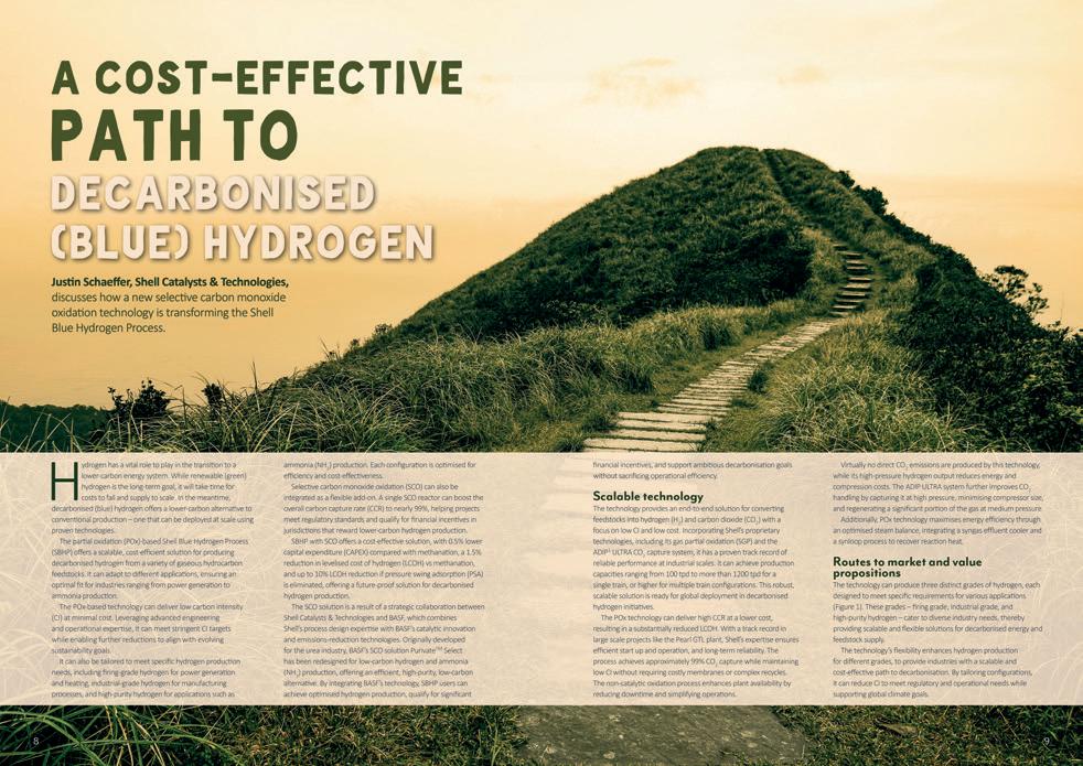
The Oil States Hydra-Lok™ system stands as a useful technology in well conversion operations. Its rapid connection capabilities and diverless operation reduce operational time and risk, while providing immediate load-bearing capacity upon installation. Originally developed for offshore infrastructure, including platform jackets and subsea templates, the system could prove particularly valuable in CCS applications. The technology’s ability to establish robust structural connections makes it ideal for reestablishing foundations in previously abandoned wells, providing the secure base necessary for CO2 storage operations.
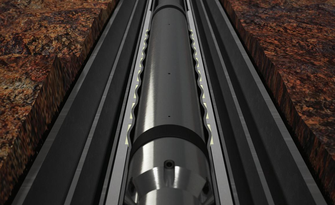
Building on this structural foundation, Oil States’ formConnect™ technology addresses the critical challenge of casing string reconnection. This innovative system delivers highpressure, high-capacity connections that meet the stringent requirements of CO2 storage. Its particular strength lies in enabling the installation of new wellhead foundations and casing hangers in wells where previous infrastructure has been removed, effectively bridging the gap between abandoned well architecture and modern CCS requirements.
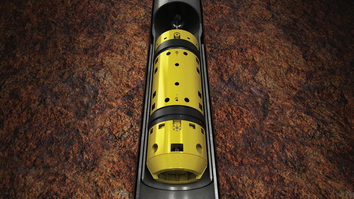
The integration of high-pressure riser systems completes the well conversion package, establishing the vital link between seabed infrastructure and surface operations. These systems work in concert with Hydra-Lok and formConnect technologies to ensure complete well control throughout the conversion process and subsequent injection operations. The pressure-tight conduit they provide is essential for both the initial conversion work and long-term CO2 injection activities.
Supporting these core technologies is a comprehensive suite of services beneficial for well conversion. Advanced well cleaning and cutting tools ensure proper preparation of the wellbore. Equally important is the availability of specialised engineering expertise and project management capabilities, enabling the development of bespoke solutions for each unique well configuration.
The combination of these technologies and supporting services provides operators with a complete toolkit for well conversion. This integrated approach, proven through field applications, offers a reliable pathway for transforming abandoned wells into valuable CCS assets, meeting both current regulatory requirements and future operational needs.
The process of converting an abandoned well into a viable CO2 storage receptacle requires a systematic, carefully orchestrated approach. Each step builds upon the previous one, creating a comprehensive transformation that ensures both operational efficiency and long-term storage durability.
The foundation of any successful conversion begins with thorough evaluation and planning. Engineers must meticulously review existing well architecture documentation, original P&A records, and current regulatory requirements to develop a comprehensive understanding of the well’s condition. This initial phase includes a detailed engineering analysis to design a conversion approach that addresses the specific challenges of a well while meeting modern CCS standards. The resulting plan serves as a roadmap for all subsequent operations.
The installation of new infrastructure begins with the Hydra-Lok swaging system, deployed with a Lynx™ connector crossover. This operation establishes a new wellhead foundation capable of supporting future CCS operations. The swaging process creates a robust metal-to-metal connection that provides immediate and reliable load-bearing capacity, beneficial for long-term stability.
Following wellhead establishment, a high-pressure riser system is installed with careful attention to tension requirements. Detailed riser analysis guides the selection of optimal connectors, ensuring compatibility with both existing infrastructure and planned CCS operations. The riser system provides the critical link between subsea operations and surface control equipment.
The formConnect technology then creates crucial pressure-tight connections within the casing string. This step is vital for ensuring the well’s ability to contain CO2 under injection pressures. Each connection undergoes rigorous pressure testing to verify its integrity, establishing a documented baseline for future monitoring.
Once the new casing connections are made and the wellhead hangers are locked down and their seals energised, comprehensive verification tests are completed to confirm the well’s readiness for either CO2 injection operations or further abandonment procedures, depending on the project timeline.
Successfully converting a well for CCS use depends on the precise execution of each step, with careful attention to quality control and verification throughout the process. This methodical approach helps ensure that converted wells meet or exceed the stringent requirements for long-term CO2 storage.
As global decarbonisation efforts accelerate, it’s anticipated that demand for CCS initiatives will grow. This presents a unique opportunity for the oil and gas industry to leverage its vast infrastructure and decades of subsurface expertise to advance CCS capacity. The thousands of wells approaching decommissioning represent not just a challenge, but a strategic lower-carbon asset as the energy industry diversifies.
The oil and gas sector is uniquely positioned to lead CCS efforts, possessing both the technical knowledge and physical infrastructure required for large-scale carbon storage. Field-proven oil and gas technologies, supported by established supply chains, are key to a cost-effective CCS industry.
Note
Garry Stephen has more than 20 years of expertise in global oil and gas offshore drilling.


In this episode, Juan Caballero, Chair of the AMPP Board of Directors, talks about AMPP’s global efforts to prevent corrosion and to protect assets, offering insight into how the association listens to its members and serves the pipeline industry.
Juan shares his insights on:
• The merger of NACE with SSPC to form AMPP.
• Materials protection challenges in 2025.
• AMPP’s training programmes, including a sneak peek into the newest offerings.
• Industry trends and how AMPP views sustainability.
• Which certifications are currently in demand.
• Digital learning for pipeliners.
• Regulations that we need to pay attention to now.
Episode Seven: UKOPA
Episode Six: TDW
Episode Five: IPLOCA


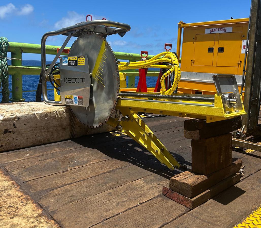
Calum Dey, Engineering Manager, Decom Engineering, details the development of new technologies designed to meet unique challenges of cutting tasks in challenging environments.
ast year, the introduction of the C1-32 Chopsaw to market – Decom’s first neutrally buoyant tool – was a significant milestone. Capable of cutting up to 32 in. OD materials of any type, this advanced technology was designed to meet the unique challenges posed in a conductor removal scope on the Brent Charlie platform in the North Sea, and sets the foundation for in-built buoyancy integration.
Due to the complexity of the conductor guideframe layout and restricted 3 m width access, the Chopsaw had to be neutrally buoyant in seawater and easily maneuverable with a single ROV. Weighing approximately 6700 kg in air but only 50 kg in seawater and with a blade diameter of 2100 mm, the C1-32 assisted with the cutting of 40 Brent Charlie multi-string conductors with an OD of 30 in., many with the added challenge of loose internal strings.

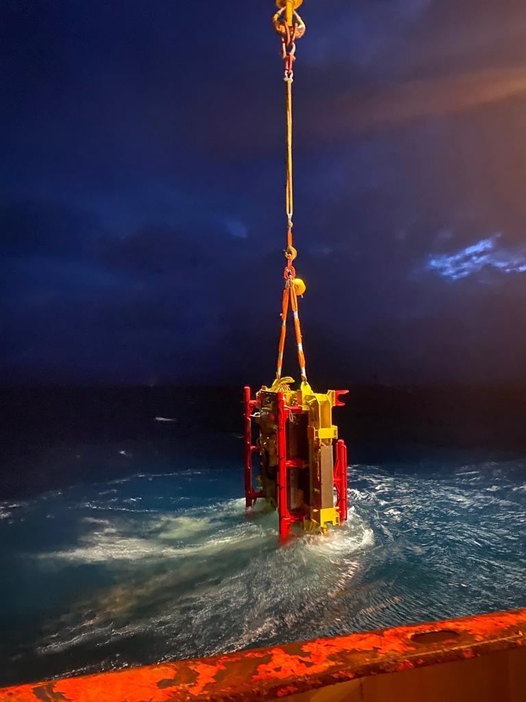
From neutrally buoyant to ultra-light, this year Decom launched the C1-16UL Chopsaw. The C1-16UL is designed to cut a wide range of materials but excels with its add-on mooring chain retention clamps, allowing for precise cutting without the risk of dropping anything to the seabed. This Chopsaw was specifically engineered to handle the demanding task of cutting flexible risers and mooring chains under tension, Riser Turret Moorings and Deepwater Tensioned Moorings. It incorporates several innovations, including a subsea-grade aluminium frame, replacing traditional steel construction, and a high-torque direct-drive hydraulic motor which has eliminated the need for a gearbox without sacrificing performance.
This tool is currently deployed on a 45 day campaign in the Shenandoah Field, Gulf of Mexico, which includes cutting studless
mooring chains in less than 20 minutes and incorporates a linked retention system to secure severed sections.
Another exciting development is Decom Engineering’s linear cutting C1-10T Tracksaw which is designed for optimal performance in confined spaces and challenging environments. Its compact design allows it to fit into tight areas with minimal headroom, making it ideal for both subsea and industrial projects.
The C1-10T has been engineered to handle complex cutting tasks, further enhancing Decom Engineering’s capabilities in offshore and industrial applications. With its ability to execute linear cuts in limited access areas and remove excess webbing, the C1-10T offers a new level of versatility and whether used for flat plate, gussets, rib
plates, or standard beam sections, this tool delivers precision and efficiency in demanding cutting scenarios.
The continual development and deployment of new tools and technology such as the C1-32, C1-16UL, and C1-10T has enabled Decom Engineering to further capture key markets, positioning the company for a successful expansion into North and South America.
The C1-24 Chopsaw has been instrumental in shaping Decom Engineering’s research and development efforts. Its successful deployment on high-profile global projects has provided critical insights that have driven the refinement of cutting technologies. By overcoming diverse operational challenges in locations such as the North Sea, the Gulf of Mexico, and the Gulf of Thailand, the C1-24 has proven to be an invaluable tool in subsea decommissioning and offshore recovery.
Through experience with the C1-24, Decom has continuously adapted its engineering approach, the necessity of achieving precise yet efficient cutting in extreme depths led to the development of custom retention clamps, reducing seabed impact and improving operational efficiency. This evolution has directly influenced the design philosophy behind the latest additions to Decom Engineering’s Chopsaw lineup, including the C1-16UL and C1-10T, ensuring that each new tool builds upon the successes and advancements of its predecessors.
One of the most impactful projects that shaped Decom Engineering’s approach to portfolio development was the recovery of 20 in. multi-string conductors from the Repsol Gyda platform in the North Sea. The C1-24 Chopsaw, powered by a topside hydraulic power unit, was used for challenging multi-string conductor cuts on X70 grade material, achieving an average cut time of just under one hour. The project highlighted the need to further develop Chopsaws to target multi-string conductors, influencing future designs to accommodate similar offshore challenges with enhanced efficiency and cutting precision.
Decom Engineering is focussed on continuous improvements in tool efficiency, safety, and reliability. Lessons learned from an extensive deployment track record in UKCS, Africa, Asia, and Australia, have led to the optimisation of cutting speeds, reduced blade wear, and enhanced deployment methods to minimise downtime. Whether cutting through hardened steel accelerator rods in the North Sea or performing high-precision subsea cutting at depths of over 1000 m in the Gulf of Guinea, each project presents unique environmental and logistical challenges.
The positive reception of Decom Engineering’s cutting solutions has strengthened its position as a trusted industry leader. Clients have consistently highlighted the reliability, precision, and efficiency of its tools, with particular praise for its ability to customise equipment for specific project needs and its rapid response times as Decom Engineering has often been called in to support when competing technologies have failed.
The integration of features such as retention clamps, hot stab panels, custom v-blocks, and advanced blade designs has allowed operators to achieve faster, safer cuts, significantly reducing operational costs. Decom Engineering’s work in offshore decommissioning and subsea infrastructure maintenance has earned acclaim from leading contractors and operators worldwide, with efficiency gains achieved through its tools, positioning Decom Engineering as a preferred partner for complex cutting operations.
Decom Engineering’s focus on research and development has been a driving force behind its continued success. Decom continuously invests in improving deployment methods, cutting efficiency, refining blade design, and optimising cutting speed while reducing operational downtime.
By analysing past campaigns, such as the C1-24’s deployment in challenging environments including the Indian Ocean and the North Sea, Decom has fine-tuned its designs to perform seamlessly in extreme conditions. The development and integration of enhanced blade technology such as replaceable tips, custom deployment frames, and increased operational flexibility ensures that tools are equipped to handle even the most demanding offshore operations with precision and reliability.
Sustainability remains a key focus of Decom Engineering’s tool development. The impact of subsea decommissioning operations on the seabed and marine ecosystems has led Decom to refine its approach, ensuring that its cutting solutions minimise environmental disruption.
The introduction of customisable clamps has been pivotal in this effort, reducing seabed dredging time from 3.5 h to just 30 minutes. These clamps allow for efficient penetration into the seabed without excessive trenching, significantly lowering operational impact. By reducing sediment disturbance, Decom Engineering supports sustainable offshore practices, aligning with industry efforts to minimise ecological damage.
Decom’s innovations and focus do not stop offshore, with the team supporting on innovative ecologically sensitive decommissioning solutions for onshore nature reserve pipeline removal. For example, Decom took its C1-12 model and adapted it with customisations including an excavator 360˚ slew ring quick coupled connection, alongside wireless remote controls, to enable safe and sensitive decommissioning.
After a strong start to 2025, the next 12 months will include cutting and infrastructure retrieval campaigns in the Gulf of Mexico, UK North Sea, North and South America, West Australia and onshore, which will drive revenues and allow further reinvestment to support ongoing development in technology and asset building.
In 1Q25 Decom built three additional C1-16UL’s, quickly following on from completing the first unit in 4Q24, which is a testament to the team’s ability to recognise common client problems and develop solutions accordingly and at pace. With two C1-16UL’s going to Brazil and the other to Australia to cut completely different materials in varying operating conditions, Decom is ensuring that its kit will continue to be put through its paces, allowing the team and tooling to thrive in their pursuit to be every client’s go-to solution for complex cutting, whether subsea, topside, or onshore.
With a successful trial for a major operator under its belt as the optimum solution for bundle cutting using the C1-46 Chopsaw, there is increased interest onshore and offshore for a wider range of new linear cutting Tracksaws, as was demonstrated earlier this year when a Tracksaw was used offshore Western Australia. With Decom securing its first two jobs ever in the Gulf of Mexico in 2Q25, there will be no reduction in the pace of development at Decom as its learning journey continues and the team innovates to meet client needs.
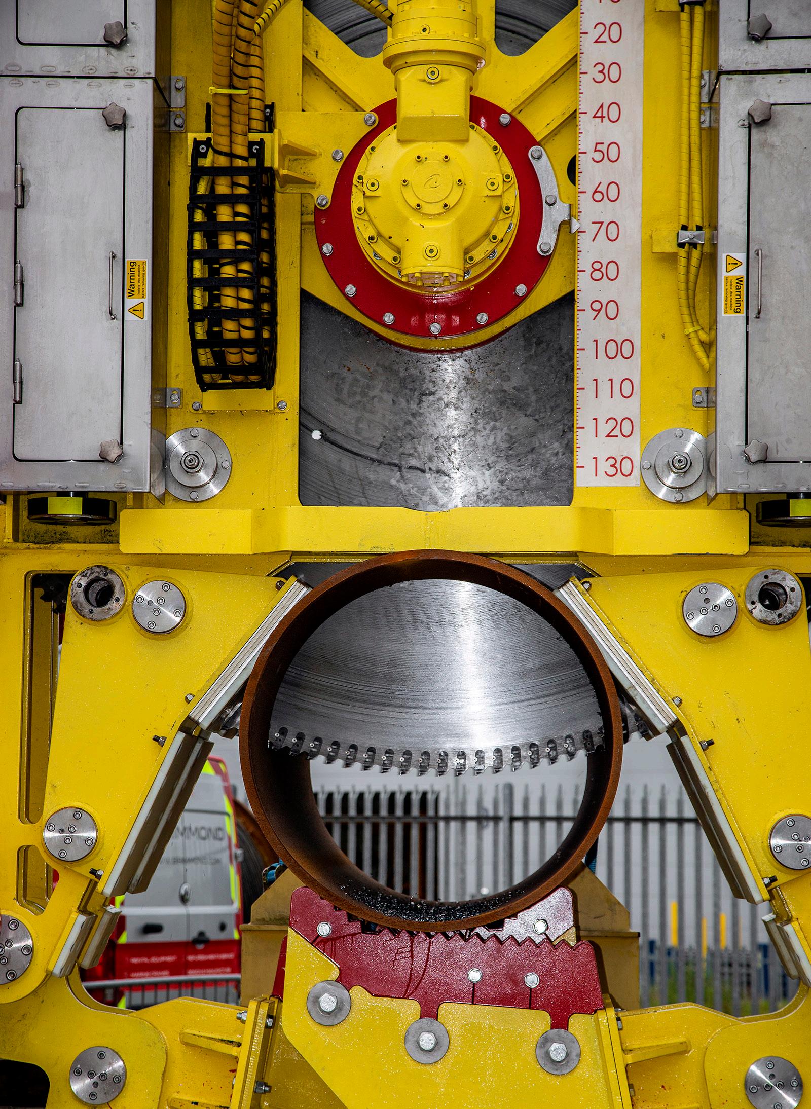
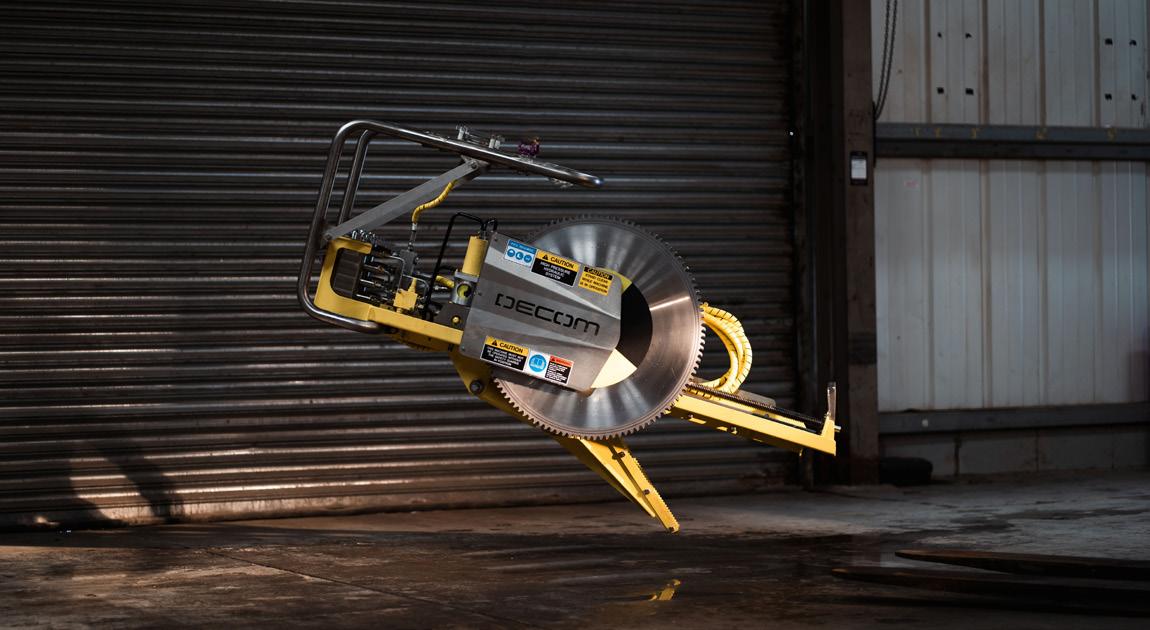


Alan Quirke, Vice President of Well Intervention & Integrity,
discusses the strategic role of well intervention and well integrity management in a capitaldisciplined, socially conscious energy supply era.
The oil and gas industry stands at a crossroads where operators face increasing pressure to meet a sustained global demand while continuing to demonstrate capital discipline.
Managing operational cost, demonstrating efficient use of resources, and evidencing environmental responsibility are all important elements of daily business management for national and international oil and gas extraction companies. Stakeholders seek a greater level of predictability, investors expect to see an acceptable level of return, and decision-makers are navigating a landscape that is becoming increasingly complex as societal sentiment fluctuates between affordable energy, energy security, and environmental sustainability.
In an effort to demonstrate relevance, oil and gas operators are challenged with maximising existing asset value, extending the productive life of wellstock and ensuring the safe and efficient delivery of operations while preparing for eventual decommissioning in a responsible and cost-effective manner.
Asset integrity, and in particular well integrity management, is the foundation for ensuring that an individual asset or well remains safe, productive and compliant throughout its lifecycle. Implementing a
robust well integrity and intervention management strategy allows operators to maximise asset longevity, mitigate risk and prevent costly failure that could otherwise lead to asset loss and premature or unnecessarily high cost well decommissioning.
As the energy sector evolves, well intervention and integrity activities are no longer just technical necessities, they are strategic imperatives.
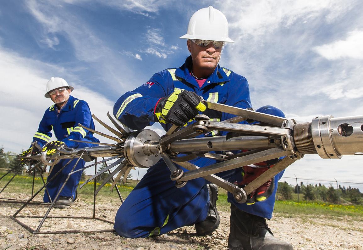
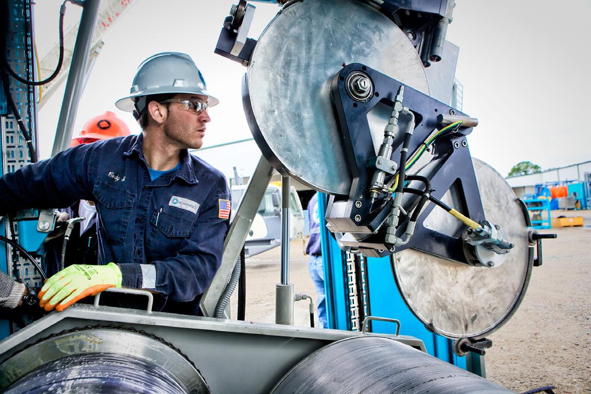
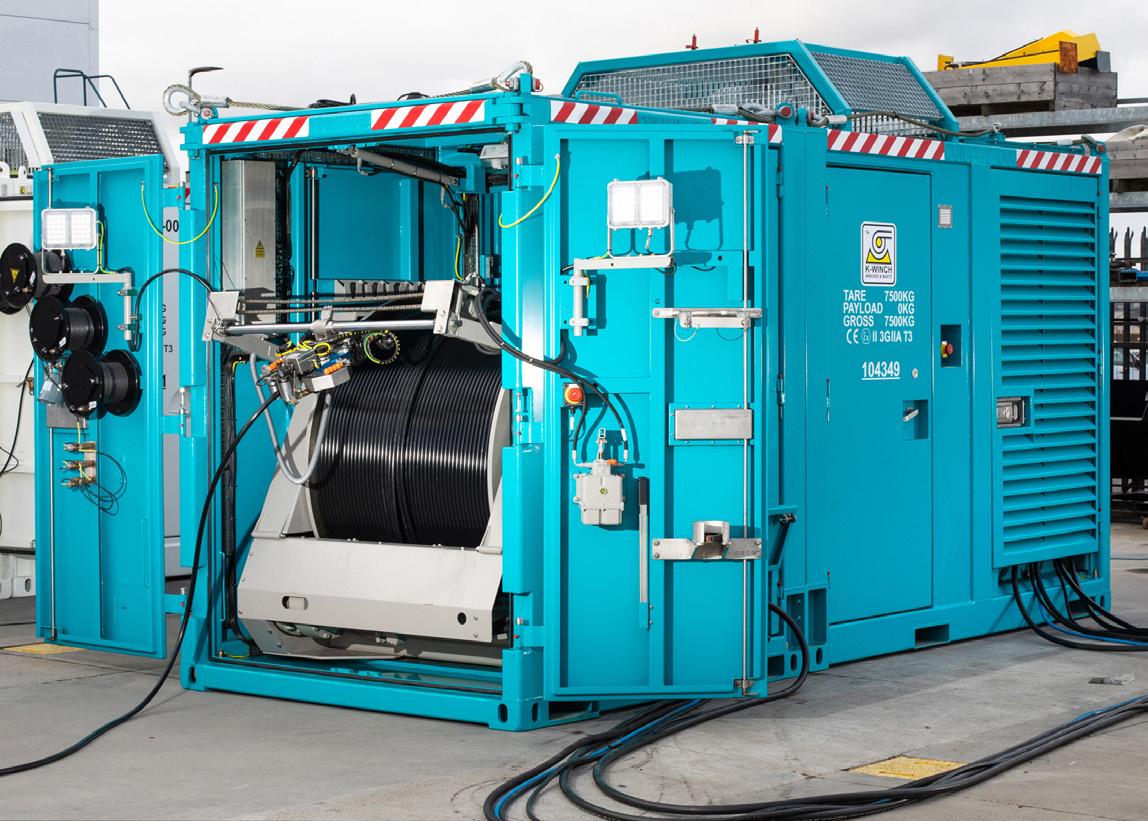
Over the past decade the oil and gas industry has seen significant disruption. Volatile commodity prices, the COVID-19 pandemic, the push for decarbonisation, and increased public scrutiny have redefined what ‘value’ means in upstream operations. Investors now favour leaner, lower-risk portfolios. Capital discipline is not a trend – it has become a mandate.
In addition, society’s uncertainty around hydrocarbon extraction arising from political debate, policy setting, and environmental activism has altered public sentiment. Operators must not only prove the economic viability of their operations but also their environmental stewardship, overall societal impact and value.
Within this new operating environment, focus has turned from capital intense development projects, delivered with the drillbit, to brownfield rejuvenation and optimisation projects that focus on existing infrastructure, prioritising late-life asset management. Rather than chasing new field developments, as a primary production strategy, operators are being encouraged, and in some cases, required to demonstrate that they are extracting maximum value from existing infrastructure before deploying new development projects.
Well intervention, whether its deployed rigless or rig supported for proactive or remedial purposes, enables the reactivation of long-term shut-in wells. It enables the rejuvenation of under-performing wells, the extension of field life and enhancement of production without the cost, complexity, or environmental impact associated with the construction of new wells.
In the operator’s capital constrained world these levers offer significant advantages. Well intervention campaigns can be highly targeted, planning is generally data-driven and outcome-focused strategies are employed with higher levels of certainty that a positive result will be delivered. Operators are increasingly using analytics, surveillance tools and real-time diagnostics to identify and de-risk activities when acting on production impairment and optimisation opportunities. The short cycle nature of well intervention planning and execution offers immediate to near term measurable return on investment not always achievable in longer cycle development projects.
Innovative technologies such as digital slickline, distributed fibre-optic sensing, coil hose fluid conveyance, and tubing/casing patches are expanding the toolkit available to operators. These innovations enable more complex downhole interventions to be performed more quickly and safely, with increased confidence in yielding successful outcomes.
Historically viewed as a compliance requirement, well integrity is increasingly seen as the foundation for assuring long-term asset value. Monitoring, understanding, and developing strategies focused on effective well integrity management not only satisfies internal and regulatory expectations but also helps
inform efficient operational performance programmes and maintains stakeholder confidence.
In the context of increasing operational scrutiny and performance expectations, well integrity understanding plays a pivotal role. Demonstrating a proactive well integrity management approach that focuses on the removal of fugitive emissions or prevention of unintended fluid releases helps to demonstrate effective environmental incident avoidance.
Investors, regulators, and stakeholders expect transparency. Asset condition assessment and management technologies like annular intervention and pressure management tools, ultrasonic imaging, and cement evaluation services are helping operators maintain a clear and auditable understanding of their well stocks integrity throughout the lifecycle.
In addition, well integrity assurance supports an operator’s license to operate. In many jurisdictions the ability to demonstrate a proactive approach to integrity management is a prerequisite to receiving construction or workover approvals, avoiding regulatory delays and maintaining societal trust.
For late-life fields, particularly those under decommissioning timelines, robust well integrity evaluation is critical. A robust well integrity monitoring and evaluation strategy can help to identify assets suitable for life extension. It can assist in prioritising well decommissioning candidates, streamline schedules, de-risk removal programmes, and minimise non-productive time during the final well decommissioning activity.
The true value unlocked by having effective well intervention and well integrity strategies lies in the integration of both into a single cohesive well lifecycle management strategy. When operators treat both aspects as interconnected rather than discrete or as sequential workstreams, synergies can be unlocked that help demonstrate enhanced safety management, deliver reduced cost, extend asset life, and optimise hydrocarbon recovery.
Integrated strategies help to reduce risk by simplifying and expediting operations, facilitating concurrent diagnostics and repair, delivering barrier verification and restoration, and providing asset benchmarking that allows informed investment decision making for impaired or underperforming wells.
Digitalisation is a critical enabler. Those activities that combine real-time data analysis and storage with historical integrity records on a single digital platform or application allow engineers to make swift and confident decisions saving time, cost, and reducing exposure on an ongoing basis.
Software based data management systems are able to provide a clear overview of operators well integrity status. Systems can be readily configured, allowing alignment with globally accepted well integrity standards and guidelines. A digital system also offers a customisable view of well integrity status and problems, facilitating proactive remedial action planning and the development of targeted well intervention programmes compliant with both regulations and company policies.
Environmental, social, and governance (ESG) matters, increasingly yielding to energy security considerations, are still important discussions held during investment decisions for hydrocarbon production projects. At the same time, energy affordability and supply stability have re-emerged as dominant themes. In this context, well intervention provides a lower cost and lower impact alternative to new drilling. It helps improve production efficiency and extend asset life with minimal surface disruption.
Proactive intervention and integrity planning on existing well assets demonstrates strong asset management discipline, regulatory compliance, and risk mitigation. These are important for investor confidence and operational performance.
As priorities shift, intervention and integrity management strategies will continue to be seen as vital tools for balancing the needs of today’s operations with the expectations of tomorrow’s stakeholders.
To fully realise the potential of well intervention and integrity in the new era, the industry must continue to innovate for and commit to the efficient management of existing well assets.
Innovation follows necessity – in a capital constrained, transition focused industry, innovators and those engaged in technology advancement will continue to react to need by designing and developing the technologies required to meet demand.
More important than innovation is commitment. Policy makers, investors, operators, and service providers need to work together to create frameworks that support efficient and transparent discussions leading to commitment. They must commit to unlocking support, investment, and activities aimed at delivering energy security and a balanced energy mix. Equally, they must commit to isolating sources of hydrocarbons in wellbores, and to well decommissioning meeting stewardship and societal expectations.
Well intervention and integrity, once considered secondary to the priority of constructing new wells, are no longer back-office functions. They are frontline strategies required to deliver value in a complex, constrained, and carbonconscious world.
Through the adoption of a proactive and integrated approach to well integrity, well intervention, and well flow optimisation management, hydrocarbon extraction companies can extend the life of existing assets while simultaneously de-risking and reducing future decommissioning costs.
By combining technical excellence with strategic foresight, operators can use well intervention and integrity management frameworks to not only demonstrate compliance, but to extend asset life, reduce risk, and build confidence with all stakeholders.
As the oil and gas sector navigates its dual mandate of delivering reliable energy and meeting evolving societal expectations, well intervention and integrity will remain essential enablers of safe, efficient, and responsible resource development long after the drill bit has stopped turning.
Nick Tranter, STRYDE, analyses new technologies seeking to address the increasing requirements of oil and gas companies to acquire high-resolution 3D seismic data in complex, high-stakes environments.


In the energy industry, where safety and efficiency are paramount, subsurface imaging using seismic methods around existing built-up infrastructure is not just an optional tool – it is a necessary investment.
Without the ability to image beneath and around existing infrastructure, companies are exposed to increased risks, project failure, and missed opportunities for further recovery of hydrocarbons or other energy sources.
Some of the primary objectives of imaging around existing oil and gas infrastructure include:
Ì Mapping remaining hydrocarbons – to delineate the boundaries of existing oil and gas reservoirs more accurately to understand the full extent of the reservoir and optimising further development or depletion plans.
Ì Monitoring reservoir changes – caused by fluid extraction or injection, which is particularly important for enhanced oil recovery (EOR) methods like water flooding, CO2 injection, or gas injection helps track how these fluids move through the reservoir and if they are reaching target zones.
Ì Geohazard identification – used to detect geohazards like shallow gas pockets, which pose significant risks during drilling. Detecting these hazards early can prevent blowouts or other drilling complications.
Ì Identifying new drilling targets for oil and gas or geothermal energy production – for optimal placement for new wells, particularly infill wells in developed fields. This minimises the risk of drilling dry wells and ensures that drilling targets untapped areas of the reservoir.
High-resolution 3D seismic data is an effective tool for overcoming challenges, managing risks, and optimising the development of brownfield oil and gas projects, making it indispensable for field management and operational continuity in complex, high-stakes environments.
Traditional seismic acquisition techniques, whether using complex cabled geophones or costly, bulky conventional nodal devices to record the seismic data, can deliver the necessary 3D seismic data insights but are often accompanied by significant drawbacks.
These systems are costly, labour-intensive, and difficult to deploy – even in open areas. In densely built-up environments, their complexity makes subsurface imaging around existing infrastructure impractical for many companies.
As a result, there has been a growing need for more advanced subsurface imaging technologies that can overcome these challenges.
This is where STRYDE’s miniature, lower-cost, and cable-free nodal technology can be a game-changer for industries requiring high-resolution subsurface imaging to make informed decisions in complex environments. It delivers superior seismic data while drastically reducing acquisition costs, deployment complexity, and environmental impact.
In just five years, over 915 000 STRYDE nodes have been delivered globally to successfully acquire high-quality seismic data on more than 300 seismic surveys across various industries, in over 60 countries. Of these
projects, 38% have focused on oil and gas exploration and production optimisation, with STRYDE nodes effectively deployed in diverse environments – from expansive deserts to operational oil and gas facilities.
Users of the STRYDE system have reported remarkable improvements in survey efficiency and cost savings of up to 50% compared to other seismic systems.
Miguel Gomez, Managing Director of geophysical services provider Seisglobe, highlighted the use of STRYDE for seismic data acquisition aimed at production optimisation across a 4 km2 area surrounding existing wells and oilfield infrastructure in Mexico. He stated:
“In this challenging environment, deploying traditional cabled geophone arrays or bulky analogue nodal devices would have been both extremely difficult and costly. The high-density spatial sampling made possible by STRYDE’s small, lightweight, and cable-free nodes was crucial to the success of this project in Mexico.”
62% of seismic surveys using STRYDE’s seismic acquisition systems have been conducted for non-oil and gas purposes. This shift reflects the growing demand for advanced seismic technologies across a variety of industries beyond traditional hydrocarbon exploration and reservoir optimisation.
One of the key drivers behind this trend is the adaptability of STRYDE’s nimble, cost-effective, and scalable seismic systems. Industries such as mining, geothermal energy, infrastructure development, and even environmental studies are leveraging STRYDE’s technology to address their unique challenges. In particular, the ability of STRYDE nodes to deliver high-resolution subsurface imaging with minimal environmental impact makes them ideal for these applications.
As industries focus on minimising risk and maximising efficiency, seismic data has become a crucial tool for understanding subsurface conditions, especially in projects that involve large-scale construction or resource extraction.
One of the key factors behind the growing demand for seismic data in non-oil and gas industries is the need to assess and mitigate geohazards, which present significant risks to infrastructure, communities, and the environment.
Geohazards such as sinkholes, earthquakes, landslides, and subsidence, require detailed subsurface analysis to effectively evaluate potential threats. STRYDE’s advanced seismic technology enables efficient and accurate detection of these hazards, providing critical data for risk assessments, land-use planning, and mitigation strategies.
These assessments are especially vital for infrastructure projects like high-rise buildings, tunnels, tailings, dams, and pipelines, where a thorough understanding of the underlying geology is crucial to ensuring safety and avoiding costly delays. STRYDE’s seismic solutions deliver fast, high-precision results, making them a key tool in identifying geohazard risks early, which in turn reduces the likelihood of accidents or disruptions.
As urbanisation and climate change continue to escalate, along with more stringent regulatory requirements, the need for reliable geohazard detection has intensified. STRYDE’s solutions are uniquely suited to meet this demand, providing accurate seismic imaging in complex environments where traditional methods such as boreholes and ground-penetrating radar fall short due to physical obstacles like buildings and underground utilities creating barriers to the effective acquisition of this data.
Industries such as construction, mining, and civil engineering have historically struggled with the limitations of geohazard detection methodologies, which are often slow, expensive, and labour-intensive, and fail to provide the necessary subsurface detail for comprehensive analysis. By leveraging STRYDE’s seismic technology, which offers cost-effective, rapid acquisition of high-resolution 3D seismic data, these industries can more effectively detect shallow geohazards, mitigate project risks, and make informed decisions that protect both infrastructure and human lives.
In 2023, Fugro reported replacing expensive and time-consuming conventional site investigation methods with their Ground Risk Management Framework (GRMF), utilising STRYDE-acquired seismic data to support the development of a 3D model of the subsurface. The objective was to reduce geotechnical uncertainty and assess its impact on the project’s schedule and quality for a major deep stormwater pumping station project in Qatar. (Chris Botha, 2023)
Fugro collected the necessary data in just nine days, followed by four weeks of analysis to accurately identify critical areas of concern –a much faster process than traditional methods. The insights gained were instrumental in the contractor pre-qualification process for the
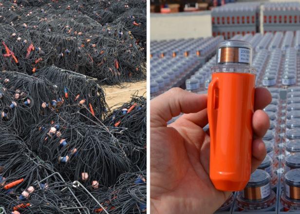
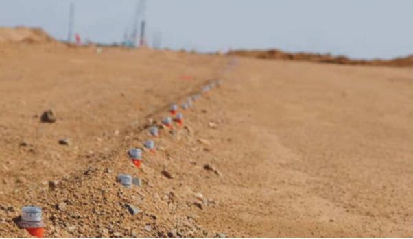
design and build contract, enabling contractors to fully quantify and price geological risks based on precise subsurface data.
This approach not only provided Fugro’s client with more accurate cost estimates but also created the opportunity for earlier design and construction start dates, streamlining the project timeline.
This project demonstrates the power of 3D seismic data for detecting geohazards, and how STRYDE is making it a viable solution even for companies with smaller budgets than those in the oil and gas sector.
In a 2024 paper published by Colombo et al. (in the Society of Exploration Geophysicists Leading Edge), ultra-dense 3D seismic surveys were highlighted as one of the most effective tools for investigating shallow geohazards, particularly when all components of elastic wave propagation are considered in the analysis.
In the article, the authors highlighted the drawbacks of traditional seismic acquisition technologies, emphasising that the primary challenge of dense 3D seismic acquisitions is the operational complexity of handling bulky equipment, along with the lengthy and costly data analysis and inversion processes. These factors have traditionally discouraged the use of 3D seismic for fast turnaround geohazard assessments.
This challenge, however, is now being addressed through advancements in the ability to acquire high-density seismic, enabled by STRYDE’s highly efficient and cost-effective standalone nodal technology. In their project, STRYDE’s lightweight, compact nodes proved to eliminate the logistical hurdles associated with conventional seismic systems, making dense 3D seismic surveys far more practical and accessible for geohazard detection.
Colombo et al. concluded that this approach, particularly when paired with machine learning algorithms for automated data processing, is highly effective for the rapid identification of nearsurface geohazards.
By significantly reducing operational complexity and processing time, STRYDE’s technology opens the door for faster, more accurate geohazard analysis in various industries.
STRYDE’s autonomous nodal technology was created to make “high-density seismic affordable for any industry”, and it has proven to do so by enabling more economical, rapid deployment, minimally invasive, high-resolution seismic data for over 15 different applications.
Ranging from oil and gas exploration, to mine expansion, civil engineering, and even elephant tracking, STRYDE provides this much-needed advancement in seismic technology, making 3D seismic imaging a practical solution for acquiring seismic data around in any onshore environment, including sensitive infrastructure like urban areas, construction sites, and gas plants.
Deployed in dense grids, these compact nodes provide seamless coverage across complex terrains, reducing the operational footprint, and allowing companies acquiring data for geohazard detection to:
Ì Reduce project risk: early detection of geohazards enables proactive measures to mitigate risk, avoid unnecessary costs, and protect people, and infrastructure.
Ì Improve efficiency: faster project timelines and accelerated decision-making.
Ì Cut site investigation costs: reduced deployment times and streamlined data analysis lower overall project costs.
This technology is enhancing subsurface imaging by making it faster, more efficient, and widely applicable to industries beyond oil and gas, offering a reliable, data-driven approach to safeguarding infrastructure and human safety.


Joel Shaw, Silverwell Energy, USA, examines how surface-controlled gas lift systems will play a greater role in maximising the potential of gas-lifted wells while minimising environmental impact and operational costs.
Gas-lifted wells have been dominated by injection pressure operated (IPO) valves over the last halfcentury. The technology is well known and offers great benefits over other forms of artificial lift in some wells and fields. Advances in electronics, manufacturing processes, and technology are delivering breakthroughs that offer more intelligence and functionality downhole. Surface-controlled gas lift is one of the most recent of these breakthroughs.
Surface-controlled gas lift allows real-time control of downhole gas lift valves from the surface. This provides some very predictable benefits such as increased production due to
deeper injection. Continuous optimisation with intervention is another benefit that is accepted but much harder to put a value on. However, many unanticipated benefits that provide the ‘icing’ on the ‘cake’ of increased production are less obvious.
IPO gas lift vs surface-controlled gas lift
Gas lift uses gas injected into the production string to reduce the hydrostatic column, allowing the reservoir pressure to push oil out of the formation. Traditionally, IPO valves have been used to allow gas to flow from the annulus to the
tubing based on the pressure in the annulus. They are placed along the length of the production string and, in general, close as the annulus pressure drops. Each IPO station acts autonomously based roughly on the pressure in the annulus. This system provides a degree of oil production, but there are shortcomings.
The pressure and temperature-related opening and closing pressure of each IPO valve must be set before installation. This requires a good understanding of the well’s behaviour. Optimisation relies on the assumption that the well will be stable over time, the reservoir characteristics are completely understood before completion, and the infrastructure will not change. However, none of these assumptions are valid, especially in unconventional fields. Correction for poor misassumptions or dynamic factors requires intervention.
The design of a well to utilise IPOs also requires concessions. One that affects production is the pressure drop required in the design of each IPO station. A good rule of thumb is a 20 - 50 psi pressure drop for each additional
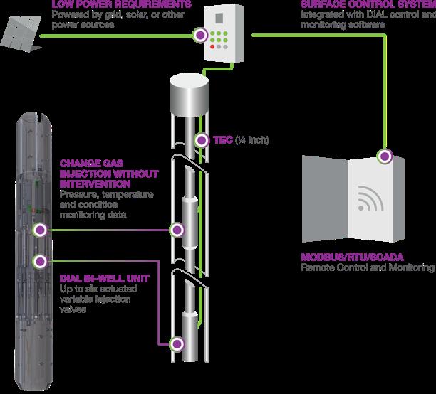
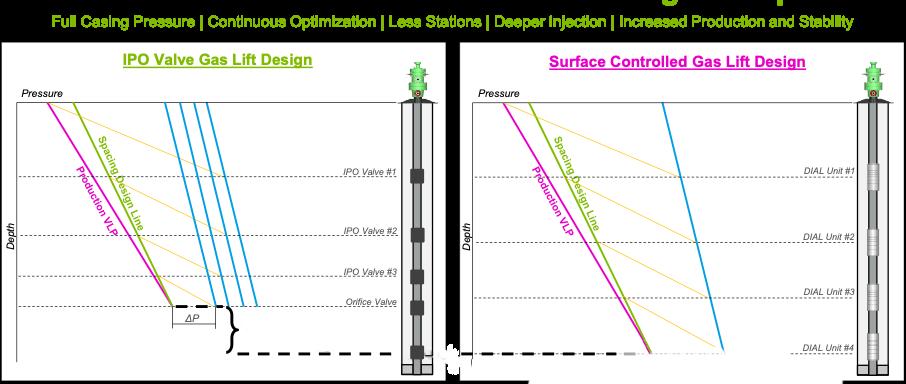
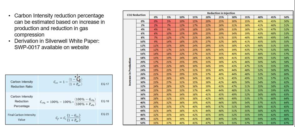
station. If 10 stations are required to get to the desired injection depth, 500 psi is lost in the design, which could be used to inject even deeper, increase the drawdown, and increase production.
Surface-controlled gas lift offers absolute control over where gas is injected and at what rate at any time in the life of the well. It also offers instant adjustment of gas injection without any intervention.
Three main components are required for surfacecontrolled gas lift: downhole flow control devices, a way to communicate with the downhole flow control devices, and the surface system to communicate with the downhole devices (Figure 1). It includes the downhole surface-controlled gas lift valves, a communication line to the surface, and a surface control system to relay communications. This control system is typically communicably attached to the operator’s surface control and data acquisition (SCADA) system.
Surface-controlled gas lift systems, such as Silverwell Energy’s Digital Intelligent Artificial Lift (DIAL) production optimisation system, allow deeper gas injection because the available pressure is not lost to guarantee the operation of IPO valves. This leads to more drawdown at the formation and increased production (Figure 2). 1
IPO completions must be designed to function when the available gas lift injection pressure is at its lowest. That provides a very conservative design that cannot then utilise increased injection pressure to increase drawdown and production.
Surface-controlled gas lift enables some completions that would not otherwise be viable. Two examples are in-situ gas lift and dual string gas lifted completions. This is because it allows absolute control of each string regardless of annulus or tubing pressures.
These are obvious examples of surface-controlled gas lift advantages. However, other advantages might be less clear.
Many benefits have come to light through experience and real-life applications. Some of these include:
Ì Diagnosing and correcting downhole hardware problems.
Ì Debris identification and recovery.
Ì Quick production recovery.
Ì Benefits that are anticipated but not obvious.
While many more problems have been diagnosed and corrected in place using surface-controlled gas lift, a few specific instances are indicative of its benefits. These include:
Ì Sensing and correcting IPO valve chatter.
Ì Finding a malfunctioning safety valve.
Ì Discovering incorrect readings from the surface flowmeter.
Ì Incorrect pressure gradients revealing gas process issues.
Ì Debris identification.
Well cleanliness is paramount for gas lift systems in general. The small ports are a point through which everything in the well annulus must pass. Surface-controlled gas lift systems
include tools to determine if there is a debris issue including temperature and pressure profiles of the tubing and annulus, position indicators, and adjusting the well to see how it reacts. Surface-controlled gas lift offers solutions for debris that are not available to more traditional forms of gas lift or are simply better suited to surface control. Some of these include:
Ì Rocking the well.
Ì Hot oil.
Ì Multiple shifts.
Ì High-pressure flow.
Ì High-pressure opening.
Each well and situation is different, so combinations of these remedial options are typically applied. Their order would normally be based on the ease of accessibility of the elements required to conduct the procedure. Table 1 offers a comparison of some of these options relative to surface-controlled gas lift and more traditional IPO systems.
IPOs require a strict procedure to ensure that each well comes online predictable, and that means slowly building up gas injection as if the well was initially unloading and coming online. This can take days or weeks.
Surface-controlled gas lift offers an alternative. With real-time individual control of each valve and reporting of the pressure sensors, the operator can use the measured pressure profile to determine which stations should be opened or closed. Wells can recover in hours or minutes, leading directly to improved production.
Returning to steady-state production after a shut-in is beneficial for all wells. With surface-controlled gas lift, a remote flip of a switch is almost all that it takes to get wells back to production.
Any number of algorithms can be used to automate bringing a well back online. These can be implemented onsite at the edge of the network, in the cloud, or at a central processing facility. A processor in the field can be encoded to act like an optimised and idealised IPO to automatically account for minor aberrations, and a central processor might be used to send commands overriding that functionality based on field needs.
Many of the benefits of surface-controlled gas lift are not discovered after wells are installed. They are anticipated ahead of time, but they are not obvious. These include:
Ì Creative elimination of scale, paraffin, asphaltene, etc.
Ì Packer test.
Ì Extended reach.
Ì Handle and utilise variations in lift gas supply pressure. Ì PPOs in hybrid systems.
Ì Carbon reduction.
Material buildup (scale, asphaltene, etc.) is a problem in wells around the world. This can be exacerbated by cooling as is common when gas expands through a gas lift valve or a surface choke. With surface-controlled gas lift, the operator is armed with the real-time pressures and temperatures of the liquids and gases. They can
utilise these in conjunction with characteristics of the various chemical constituents and downhole flow control to steer clear of dangerous areas on the pressure temperature chart that might create precipitates.
Offshore wells are another arena subject to buildups in the flow lines. Their lift gas infrastructure is often on the ocean floor and at low temperatures, and choking on the cold ocean floor leads to even more problems. Even worse, inaccessibility exacerbates the problem. Surface-controlled gas lift eliminates the challenge by reducing or removing choking on the ocean floor and moving it downhole where there is elevated temperature.
Surface-controlled gas lift offers operators more options for setting and testing a completion. One example is an annulus test after a completion has been landed and the production packer is set. If tubing-conveyed IPOs are used, it is impossible to test the packer by pumping up on the annulus. If side pocket mandrels are used, dummies must be installed during the packer test. Surface-controlled gas lift
oil
High-pressue flow
GL Stations opened/ closed based on hydrostatic pressure; may change as pressures change dynamically in the tubing or annulus
Injected solvent may change hydrostatics and open or close the desired valves limiting effectiveness
As the pressure increases to create more flow through the valve, it can open gas lift valves near the surface
High-pressure opening
Conventional gas lift valves open gradually, so they cannot be instantly opened against high-pressure
Operator selects which actuators are opened or closed. These setting will not change as the pressure changes
Specific valves can be opened or closed based on the well needs
Upper valves can be maintained closed regardless of the injection pressure
DIAL valves can be closed from the surface while annulus pressure builds. Then any valve can be instantly opened to dislodge material
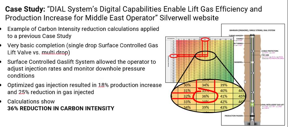
4. Optimisation of a surface-controlled gas lift well in Bahrain showed an 18% production increase and a 25% gas injection reduction, representing a 36% reduction in ongoing carbon intensity.
valves can simply be closed for the test and reopened once the packer integrity is verified. This has become common practice.
Surface-controlled gas lift has also become the standard for highly deviated and extended-reach wells. As the deviation increases, it becomes more difficult to access side pocket mandrels with slickline and eventually downhole tractors are required. However, tractors are expensive, and using kickover tools gets risky as wells deviate more and more from vertical. Surface-controlled gas lift does not require any intervention for sealing and optimisation, so it is becoming a standard in regions such as the North Slope and the Gulf of Oman where extendedreach wells benefit from gas lift deep into the build section.
Gas supply to gas-lifted wells can be unreliable. They can fluctuate wildly based on issues like new wells coming online, leaks, and compressor failure or maintenance. A production pressure operated (PPO) system must be designed to operate at the lowest possible injection pressure. Unfortunately, this means that additional injection pressure cannot be utilised when it is available. Surface-controlled gas lift allows the operator to optimise both when little pressure is available as well as when excessive pressure is available, so long as there are no IPOs in the string (such as with a hybrid system).
Hybrid gas lift systems are sometimes better off using production pressure-operated (PPO) gas lift valves than IPO valves. This is surprising as the shortcomings of PPOs compared to IPOs have almost completely discouraged the use of PPOs: reduced flow capability, no feedback as to where injection is occurring, prone to multipointing, and less accurate opening/closing pressures. All these hurdles are overcome when they are used for unloading a hybrid surfacecontrolled gas system.
If there are large injection gas fluctuations in a field, IPOs must be adjusted to operate at the lowest possible injection pressure. If the available pressure increases and the operator desires to use that pressure to inject deeper, the upper IPO will open and cause multipointing. PPOs rely on tubing pressure, so increasing the injection pressure to increase production by
increasing injection depth will not open upper valves and have a deleterious effect on the system.
Surface-controlled gas lift can reduce the carbon intensity of oil production. It can reduce methane emissions by reducing slugging, flaring, and exhausting from blow-off valves. These are often unpredictable events, but surfacecontrolled gas lift also reduces emissions predictably. Gas is compressed before injection, and much of that pressure is lost in surface chokes and not utilised to inject deeper. The carbon intensity reduction is based on increased production from injecting deeper while using the same or less gas (Figure 3). Optimisation of a surface-controlled gas lift well in Bahrain showed an 18% production increase and a 25% gas injection reduction. This represents a 36% reduction in ongoing carbon intensity for that well (Figure 4).
Surface-controlled gas lift represents a significant advance in artificial lift technology, offering a host of benefits over traditional IPO valves. Surface-controlled gas lift systems such as the Digital Intelligent Artificial Lift (DIAL) system from Silverwell Energy, provide operators with real-time control and flexibility, leading to advantages in optimising production and addressing operational challenges.
The benefits of surface-controlled gas lift systems, such as diagnosing and correcting downhole hardware problems, quick production recovery after frac hits or shut-ins, and improved efficiency, underscore the flexibility and potential of this technology to deliver significant time and financial savings for operators – the ‘icing’ on the ‘cake’.
As the industry continues to evolve, surface-controlled gas lift systems will play a greater role in maximising the potential of gas-lifted wells while minimising environmental impact and operational costs.
1. FAUX, S., GLENDAY, T., ‘The Benefits of Introducing Intelligent Gas Lift Management to Create a Smart Field’.