4 minute read
519 Telehandler REAR AXLE


Rear Axle Installation
STEP 1
STEP
Template
Step 6
Remove the support stands from under the axle and lower the tires to the floor. Torque all wheel nuts to a final torque of 450 ft.-lb. (607 Nm) torque.

Step 7
Reinstall the driveshaft to the axle using the four mounting bolts. Tighten the four bolts to 30 ft.-lb. (40.5 Nm) torque.
NOTE: Use Loctite 271 thread lock (or equivalent) on the threads of the bolts.
Step 8
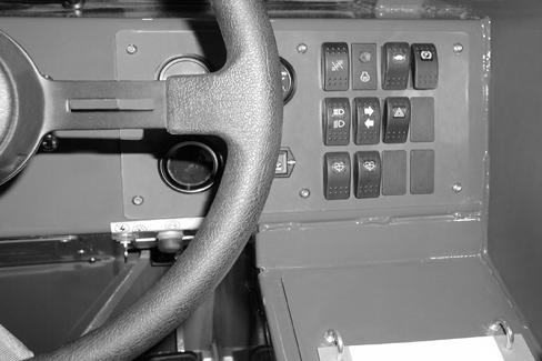
Start the engine, apply the park brake (1). Move the steer mode switch to the 4-wheel steering position (2). Turn the steering wheel in one direction until the wheels reach their travel limits and back the other way to their travel limit. Repeat this procedure several times until the air is removed from the circuit.
Step 9
Shut down the engine. Check for leaks. Correct any leakage found. Check fluid level, add fluid if needed.
Template Name: OML_2_colRac 0-00000
Template Date: 1997_02_12
Template Name: OML_2_col907871
Template Date: 1994_04_22
519 Telehandler FRONT AXLE
General Information
If steering cylinder, brakes or differential repairs are required, the axle assembly must be removed from the chassis. If only axle steering knuckle or outboard planetary service is required, the axle assembly will not require removal from the chassis.
Procedures used to remove the axle will depend on machine location and the type of lifting equipment available. The following axle removal and installation procedures, using one 10-ton hydraulic floor jack for lifting the machine, and to lift and lower the axle assembly, can be done in the field or in the shop. The machine must be parked on a solid and level surface.
Before starting inspection and repair, move the machine onto a level surface, shut down the engine, and release all hydraulic pressure. Always block the boom securely, or lower it to full ground contact. Place all controls in neutral.
Warning
Tires may be filled with liquid ballast. If filled with liquid ballast the wheels will be extremely heavy. To prevent injury, remove ballast or use proper wheel handling equipment when dismounting the wheels from the axle hubs.
Front Axle Removal
BEFORE cleaning, lubric ating, or performing service on this equipment, refer to the MANDATORY SAFETY SHUTDOWN
PROCEDURE in Section 100 (Personal Safety Information And Decal Locations).
STEP 1
NOTE: For ease of service it is recommended that any attachment be removed prior to performing axle service.
Relieving Hydraulic Pressure
1.Fully retract the telescoping boom.
2.Raise the telescoping boom far enough to be able to remove the axle from under the frame. Block the boom using suitable blocking.
3.Turn the keyswitch to the OFF position to shut down the engine. (See Mandatory Safety Shutdown Procedure.)

4.Loosen the hydraulic fill cap to relieve residual pressure in the system.
5.Move the joysticks several times to relieve hydraulic pressure in that circuit.
Step 2
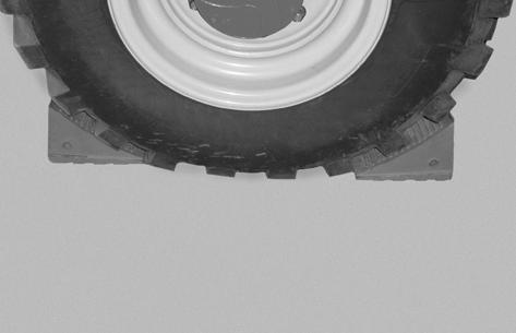
Place blocks in front and behind the rear wheels to prevent the machine from rolling when lifted.
Template Name: OML_2_col
Template Date: 1994_04_22
STEP 8
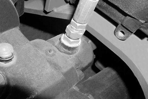
Disconnect the case drain inlet hose.
STEP 9
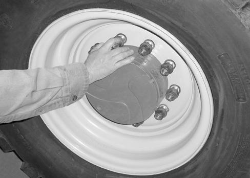
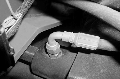
Disconnect both steering cylinder hoses. Cap fittings and plug hoses.
STEP 10
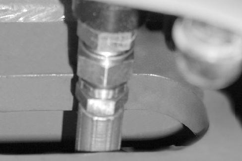
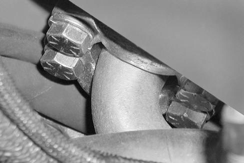
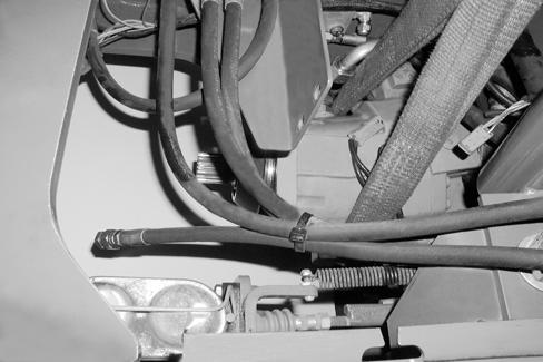
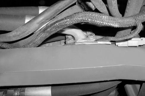
Disconnect the park brake hose (1) and service brake hose (2).

NOTE: If there is insufficient space at the axle, unhook the hoses at the manifold and solenoid.
STEP 11
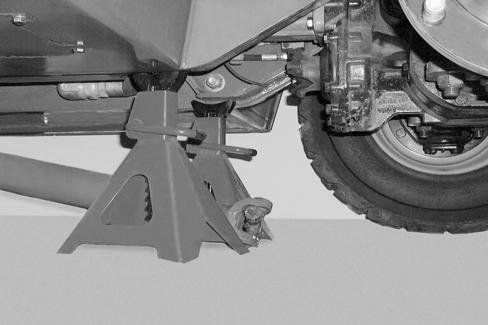
Place a floor jack under the front axle and support the frame with a pair of jack stands. Be sure the jack stands are properly rated to support the chassis. Lift the front axle and frame assembly high enough to safely remove the wheels.
Template Name: OML_2_col
Template Date: 1994_04_22
STEP 12
STEP 15
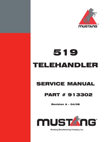
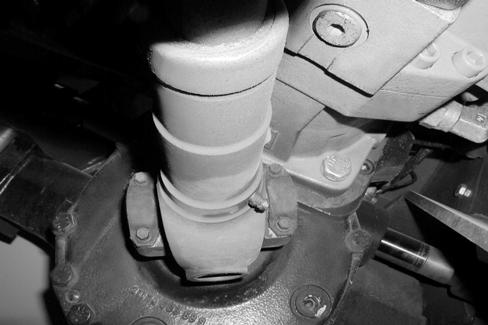
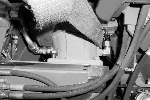
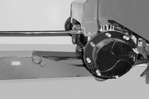
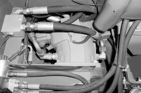
Support the drive motor (1) with a lifting strap and a suitable lifting device.
STEP 13
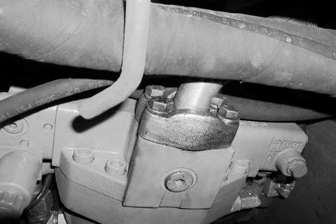
Remove the four mounting bolts (1) that hold the drive motor (2) to the front axle. Slide the drive motor rearward away from the front axle and off the drive gear.
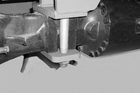

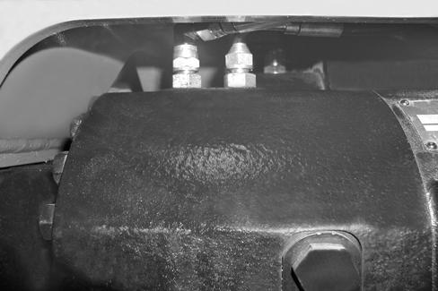
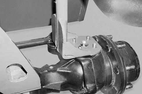
Remove the four nuts, plates and bolts that hold the axle to the frame.
STEP 18
Carefully lower and roll the axle housing forward with the floor jack. Watch for hose and harness interference during axle removal.
STEP 19
After the axle is removed, have adequate stands and work surface to support the axle safely while performing the repair procedure.
NOTE: If axle repair is required, contact your dealer.

Template Name: OML_2_col
Template Date: 1994_04_22
Front Axle Installation
Roll the axle under the front frame. Lift the axle upward being carefull not to pinch any hoses or harnesses.
Install a new O-ring (1) on the drive motor and carefully align the drive mo tor with the axle. Be sure the motor shaft slides easily into the top gear of the front axle. Tighten the four drive motor bolts to 158 ft.-lb. (214 Nm) torque.
Install and tighten the axle retaining bolts, nuts and plates. Tighten the bolts to 480 ft.-lb. (650 Nm) torque.
Re-connect the service brake (1) and parking brake (2) hoses to the front axle.
Template Name: OML_2_col907871 Template Date: 1994_04_22
Re-connect both hoses (1) (2) to the drive motor.
Re-connect the RH and LH steering cylinder hoses.
Re-connect the drive motor harness.
Template Name: OML_2_col
Template Date: 1994_04_22
519 Telehandler FRONT AXLE
STEP 8
STEP
STEP 9
Install the fender. Torque all nuts to 75 ft.-lb. (100 Nm).
STEP
STEP 12
STEP 13
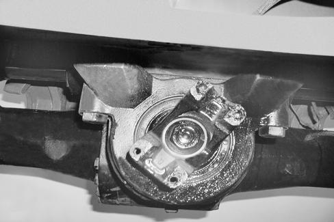
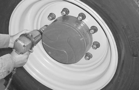
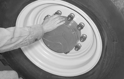
Torque wheel nuts to 450 ft.-lb. (607 Nm) torque.
STEP 14
STEP 17
Bleed the park and service brakes. See Section 505 of this Service Manual.
STEP 18
Start the engine; apply the park brake (1). Move the steer mode switch to the 4-wheel steering position (2). Turn the steering wheel in one direction until the wheels reach their travel limits and back the other way to their travel limit. Repeat this procedure several times until the air is removed from the circuit. Remove air from the hydrostatic system by cycling the drive forward and backward until the air is removed from the circuit.
STEP 19
Shut down the engine. Check for leaks. Correct any leakage found. Check fluid level; add fluid if needed.
Template Name: OML_2_colRac 0-00000
Template Date: 1997_02_12
Template Name: OML_2_col907871
Template Date: 1994_04_22
519 Telehandler BRAKES
Bleeding Service Brake
BEFORE cleaning, lubric ating, or performing service on this equipment, refer to the MANDATORY SAFETY SHUTDOWN PROCEDURE in Section 100 (Personal Safety Information and Decal Locations).
Step 1
Step 2
With an assistant in the operator’s seat, apply pressure on the brake pedal. Open the bleed screw to relieve air in the system. Close the bleed screw and release pressure on the brake pedal. Repeat the procedure until all air is removed from the system.

STEP 3
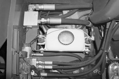
Check the brake fluid level. Add Sunco Multi-ATF or equivalent brake fluid if needed.

STEP 4
Check for proper brake operation.
Template Name: OML_2_col 907871
Template Date: 1994_04_22