5 minute read
519 Telehandler HYDRAULICS


Extension Cylinder Counterbalance Valve Quick Test
Step 36
Step 38
Step 37
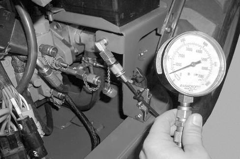
Start the engine and run at high idle. Extend the boom approximately 6 feet (2 meters). Watch the pressure gauge as the boom is slowly retracted, the gauge should read less than 3350 psi (230 bar).
If the pressure is less than 3350 psi (230 bar), proceed to the next step.
If the pressure is more than 3350 psi (230 bar), replace the extend cylinder counterbalance valve.
Retract the boom to the end of the extension cylinder stroke and hold the joystick in the RETRACT position. The pressure gauge should read 3350 psi (230 bar).
If the pressure is less than 3350 psi (230 bar), go to Step 29 of the EXTENSION CYLINDER QUICK TEST.
If the pressure is 3350 psi (230 bar), proceed to the next step.
If the pressure is more than 3350 psi (230 bar), go to the Main Control Valve Pressure Relief Test and Adjustment section of this manual before proceeding to the next step.
Extension Cylinder Counterbalance Valve Direct Test
Step 39
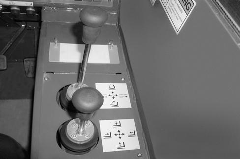
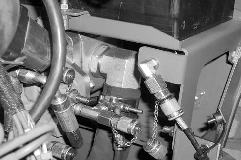
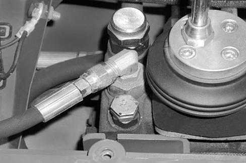
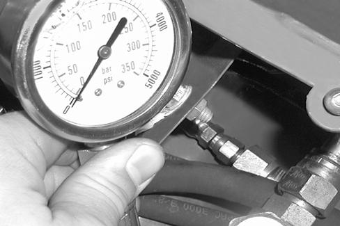
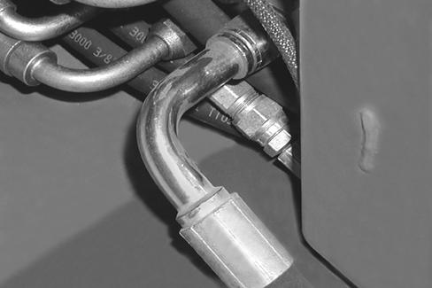
Shut off the engine. Remove the pressure gauge. Remove the hose (1) from the retract tube fitting (2). Install a 5000 psi (350 bar) pressure gauge (3) between the hose (1) and retract tube fitting (2).

WARNING: The hose must be long enough to read the gauge while standing clear of the forklift.
Step 40
Start the engine and run at high idle. Extend the boom approximately 6 feet (2 meters). Watch the pressure gauge as the boom is slowly retracted. The gauge should read less than 3350 psi (230 bar) as the boom is retracted.
If the gauge is not at 3350 psi (230 bar), replace the extend cylinder counterbalance valve.
Template Name: OML_2_col0-00000
Template Date: 1994_04_22
519 Telehandler HYDRAULICS
Main Control Valve Pressure Relief Test And Adjustment
Main Relief Valve Quick Test And Adjustment
STEP 41
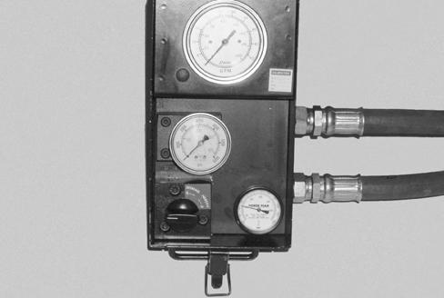
Install a 5000 psi (350 bar) pressure gauge and hose on the battery tray test port.
WARNING: The hose must be long enough to observe the pressure gauge from inside the cab or standing clear of the forklift.
STEP 42
Start the engine and run at high idle. Retract the boom until the boom extension cylinder is at the end of its stroke and hold the joystick in the RETRACT position. The pressure gauge should read 3350 psi (230 bar).
If the pressure is less than 3350 psi (230 bar), proceed to the next step.
If the pressure is more than 3350 psi (230 bar), proceed to Step 48.
Step 43
Lower the boom until the lift cylinders are at the end of their stroke and hold the joystick in the LOWER position. The pressure gauge should read 3350 psi (230 bar).
If the pressure is 3350 psi (230 bar) go to the Extension Cylinder Direct Test in this manual.
If the pressure is more or less than 3350 psi (230 bar) proceed to the next step.
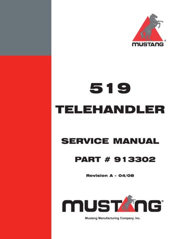
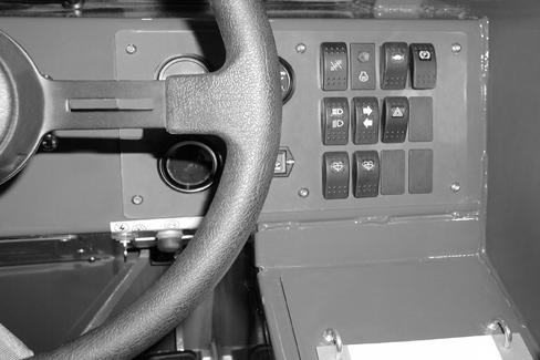
Shut off the engine. Remove the four screws securing the joystick panel (1). Remove the main relief valve cap (2) and turn the adjusting screw (3) clockwise to increase and counterclockwise to decrease the pressure.
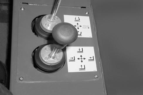
NOTE: 1 turn of the adjusting screw (3) will change the pressure approximately 800 psi (55 bar).
Install the main relief valve cover.
Repeat Steps 46, 47 and 48 until the pressure gauge reads 3350 psi (230 bar).
If the pressure can be adjusted to 3350 psi (230 bar), proceed to Step 49.
If the pressure is more than 3350 psi (230 bar) and does not change when the adjusting screw (3) is turned counterclockwise, replace the main relief valve.
If the pressure is less than 3350 psi (230 bar) and does not increase when the adjusting screw is turned clockwise, go to the Pump Pressure Test in this manual before replacing the relief valve.
STEP 45
If the pump, relief valve or any cylinders are repaired or replaced, repeat Steps 46, 47 and 48 to set the main control valve relief pressure at 3350 psi (230 bar).
STEP 46
Template Name: OML_2_col0-00000
Template Date: 1994_04_22
519 Telehandler HYDRAULICS
Joystick Control Test
STEP 47
If the forklift does not respond to one of the joystick controller commands, proceed to the next step.
STEP 48
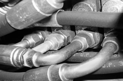
Remove the hose from the function to be tested. Install a 5000 psi (350 bar) pressure gauge and hose between the hydraulic port and the supply hose.
1.Boom (UP)
5.Boom (Down)
Step 49
WARNING: The hose must be long enough to observe the pressure gauge from inside the cab or standing clear of the forklift.
Start the engine and run at high idle. The park brake must be ON. Hold the joystick in the position of the port to be tested. The pressure gauge should read 3350 psi (230 bar).
If the pressure is 3350 psi (230 bar) but there is no response to the joystick command, repair or replace the control spool, or the control valve section, or the entire main control valve.
If the pressure is less than 3350 psi (230 bar), proceed to Step 55.
If the pressure is more than 3350 psi (230 bar), proceed to the next step.
Step 50
Shut off the engine. Replace the main control valve. Repeat Step 53.
Step 51
Step 53
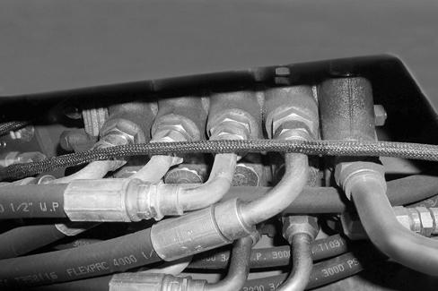
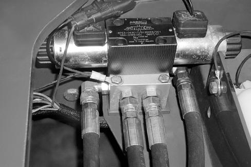
Shut off the engine. Remove the pressure gauge tee adapter (1) from the hydraulic fitting (2). Install a cap in the hydraulic solenoid and a plug in the tee adapter.

Step 52
Start the engine and run at high idle. Hold the joystick in the position of the function being tested. The pressure gauge should read 3350 psi (230 bar).
If the pressure is more or less than 3350 psi (230 bar) replace the main control valve.
Shut off the engine. Remo ve the pressure gauge from the hydraulic supply hose and install the supply hose on the valve port.
Template Name: OML_2_col0-00000
Template Date: 1994_04_22
519 Telehandler HYDRAULICS
Steering Circuit Pressure Test
Steering Circuit Pressure Quick Test
STEP 54
Install a 5000 psi (350 bar) pressure gauge to the main valve test port on the battery tray.

WARNING: The hose must be long enough to observe the pressure gauge from inside the cab or standing clear of the forklift.
STEP 55
Start the engine and run at high idle. Move the Steer Mode Switch (1) to the 4-Wheel Steering position. Turn the steering wheel in one direction until the wheels reach their travel limits and hold. The pressure gauge should read 2400 psi (165 bar).
If the pressure is more or less than 2400 psi (165 bar), proceed to the next step.
If the pressure is 2400 psi (165 bar), but the steering does not work properly, c heck the steering linkage and pivot points, and the Steering Mode Valve, before repairing or replacing the steering control unit.
STEP 56
Remove the cap (1) from the steering relief valve on the main control valve. Loosen the nut (2) and turn the adjustment screw (3) cl ockwise to increase the pressure or counterclockise to decrease the pressure.
NOTE: One turn is approximately 650 psi (45 bar).

Steering Circuit Pressure Direct Test
Step 57
Step 58
Shut off the engine. Re move the pressure gauge from the PF port (1) and reconnect the hydraulic hose to the PF port fitting (2).
Remove the supply hose (1) from port P (2) of the Steer Mode Valve. Install the inlet hose from an inline flowmeter on the supply hose (1) and the flowmeter outlet hose on the Steer Mode Valve Port P (2).
Step 59
OPEN the load control valve (1) of the flowmeter. Start the engine and run at idle. Turn the steering wheel in one direction until the wheels reach their travel limits and hold. Slowly close the load control valve.
If the pressure is less than 2400 psi (165 bar), repair or replace the steering control unit.
If the pressure is 2400 psi (165 bar), proceed to the next step.
Template Name: OML_2_col