3 minute read
519 Telehandler ELECTRICAL


Steering Mode Circuit Tests
STEP 33
(1).
(1)
STEP 34
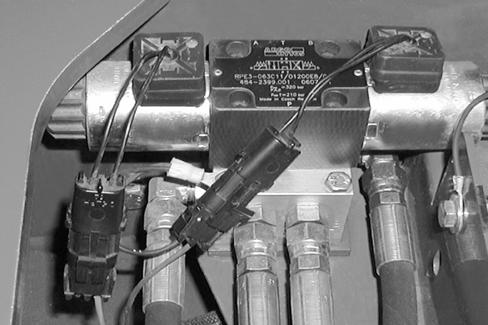
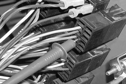
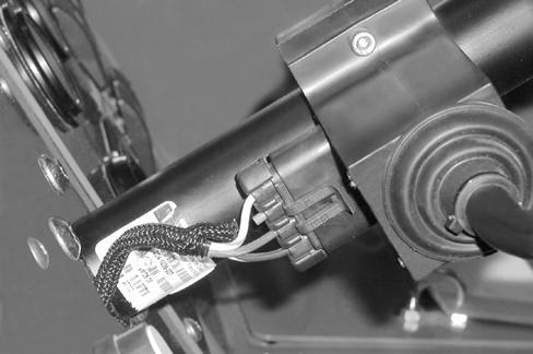
Set the multimeter to read DC volts. Disconnect the 4-wheel steer wire harness (green and black wires) from the steer mode solenoid connector located under the front cover.
Install the positive (+) test lead in the orange/white prong of the wire harness. With the key switch in the ON position and the steer mode switch in the crab steer position, the multimet er should read 12 to 13 volts.
If there is no voltage, proceed to Step 35.
If there is 12 to 13 volts, but the 4-wheel steer mode does not function, replace the solenoid valve. Connect the wire harness to the 4-wheel steer mode solenoid connector.
Step 35
Step 36
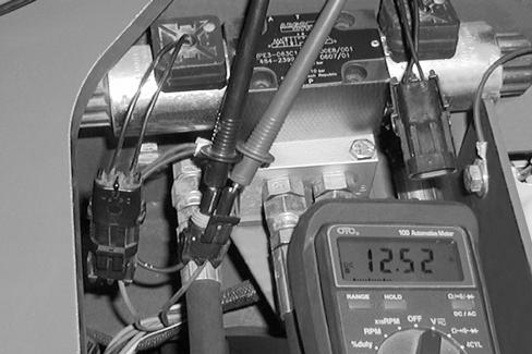
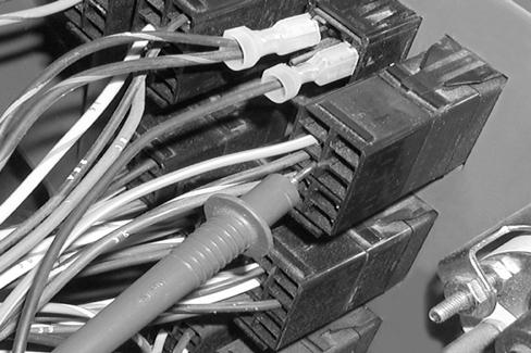
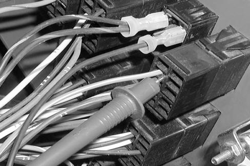
Disconnect the 4-wheel steer wire harness (green/ blue and black wires) from the steer mode solenoid connector. Install the positive (+) test lead in the green/blue wire prong of the wire harness. With the key switch in the ON position and the steer mode switch in the 4-wheel steer position, the multimeter should read 12 to 13 volts.
If there is no voltage, proceed to the next step.
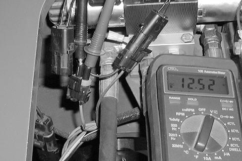
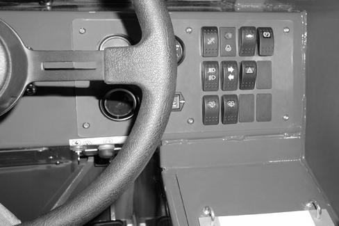
Complete step 13 to remove the instrument panel. Connect the positive (+) test lead to the black/yellow wire terminal of the steer mode switch located on the left side of the instrument panel. With the key switch in the ON position the multimeter should read 12 to 13 volts.
If there is no voltage, repair or replace the black/ yellow wire between the switch and the fuse panel. If there is 12 to 13 volts, proceed to the next step.
Step 37
If there is 12 to 13 volts, but the 4-wheel steer mode does not function, replace the solenoid valve. Connect the wire harness to the 4-wheel steer mode solenoid connector.
Connect the positive (+) test lead to the orange/white wire terminal of the steer mode switch. With the key switch in the ON position and the steer mode switch in the CRAB STEER position, the multimeter should read 12 to 13 volts.
If there is no voltage, replace the steer mode switch. If there is 12 to 13 volts, but no voltage in Step 41, repair or replace the orange/white wire between the switch and the solenoid valve.
Step 38
Connect the positive (+) test lead to the green/blue wire terminal of the steer mode switch. With the key switch in the ON position and the steer mode switch in the 4-WHEEL STEER position, the multimeter should read 12 to 13 volts.
If there is no voltage, replace the steer mode switch.
If there is 12 to 13 volts, but no voltage in Step 42, repair or replace the green/blue wire between the switch and the solenoid valve.
Step 39
Template Name: OML_2_colRac 0-00000
Template Date: 1997_02_12
Alt= to hide template information Alt+ to display template information
General Table Of Contents
Template Name: OML_1_col907871
Template Date: 1994_04_22
519 Telehandler BATTERY
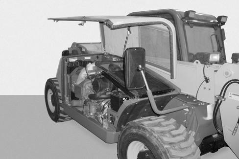

Battery Removal
BEFORE starting any cleaning, lubricating or servicing of this equipment, refer to the MANDATORY SAFETY SHUTDOWN PROCEDURE in the Safety Section of this manual.
Step 1
Warning
BATTERY ACID CAUSES SEVERE BURNS. Batteries contain sulfuric acid. Avoid contact with skin, eyes or clothing. Antidote: EXTERNAL - flush with water. INTERNALDrink large quantities of water or milk. Follow with milk of magnesia, beaten egg or vegetable oil. Call a physician immediately.
EYES - Flush with water for 15 minutes and get prompt medical attention. BATTERIES PRODUCE EXPLOSIVE GASES. Keep sparks, flame and cigarettes away. Ventilate when charging or using in enclosed space. Always shield eyes when working near batteries. KEEP OUT OF REACH OF CHILDREN.
Warning
When working around storage batteries, remember that all of the exposed metal parts are LIVE. Never lay a metal object across the terminals because a spark or short circuit will result.
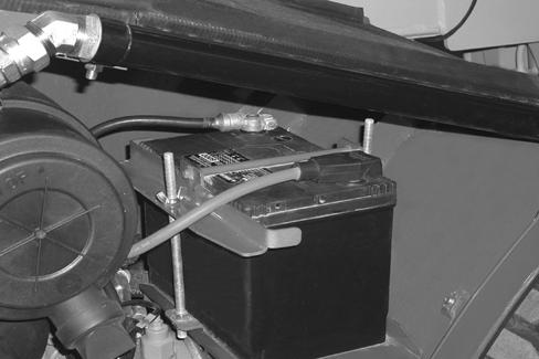
Step 2
Warning
Always remove the negative (-) battery cable first so you do not cause a spark at the battery. A spark can cause the battery to explode and cause personal injury or damage to the machine.
Template Name: OML_1_col907871 Template Date: 1994_04_22
Step 3
Step 5

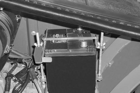
Step 4
Template Name: OML_1_col907871
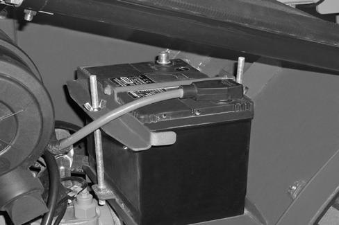
Battery Installation
STEP 6
STEP 7
Warning
Always install the negative (-) battery cable last so you do not cause a spark at the battery. A spark can cause the battery to explode and cause personal injury or damage to the machine.
IMPORTANT: Be sure the cables and battery terminals are clean and tight.
IMPORTANT: Be sure the battery cables are routed correctly and secured away from sharp edges, hot or moving objects.
Close the engine cover.
Template Name: OML_2_colRac 0-00000
Template Date: 1997_02_12 to hide template information to display template information
General Table Of Contents
Template Name: OML_2_col907871
Template Date: 1994_04_22
519 Telehandler STEERING CONTROL VALVE
Steering Control Valve Removal
BEFORE starting any cleaning, lubricating or servicing of this equipment, refer to the MANDATORY SAFETY SHUTDOWN PROCEDURE in the Safety Section of this manual.
STEP 1
Disconnect the battery ground cable.
STEP 2
Loosen the hydraulic oil fill cap to relieve residual pressure on the hydraulic system.
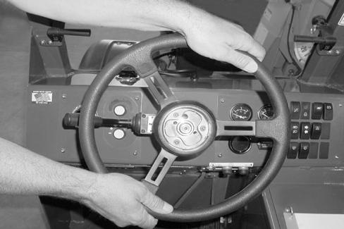
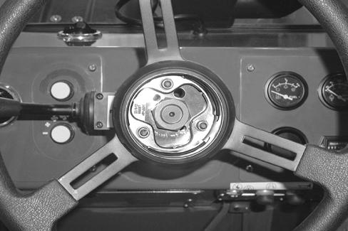
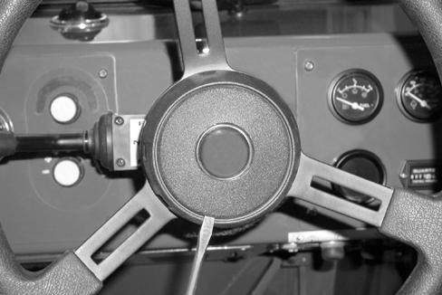
Loosen and remove the steering wheel nut.
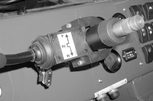
Loosen the two bolts (1) and remove the gear selector (2) from the steering column. Mark the position of the gear selector for correct reinstallation.
Template Name: OML_2_col
Template Date: 1994_04_22
907871
Alt= to hide template information Alt+ to display template information