5-11 Upper Swing Body: Pump 4 Regulator Disassembly and Assembly Procedures 1.
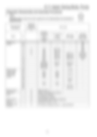
Tools The table below shows the tools required for the disassembly and assembly of KR3G-9*04-HV. Required tools are indicated with {
Tool name and dimensions
Name
Hexagon bar wrench
Closed wrench Socket wrench Double-head (single-head) wrench
Monkey wrench Screwdriver Pliers Torque wrench Steel rod Hexagon socket head bolt
B
Part name Hexagon socket head bolt (shouldered bolt) M5 M6 M8 M10 M12 M14 M16 M18 M20 M22 M24 M27 M16 M18 M20 M30 -
PT mounted valve (PT screw) BP-1/16 BP-1/8 BP-1/4 BP-3/8 BP-1/2 BP-3/4 BP-1 M16 M18 M20 M30 -
ROH plug (PF screw)
2 2.5 3 4 5 6 8 10 12 14 17 19 22 24 27 30 36 41 46 50 55 -
{ { { { { {
Medium-sized × 1
-
{
For pulling out adjusting ring M4, L = approximately 50
{ { {
B
ROH-1/4 ROH-3/8 ROH-1/2 ROH-3/4 ROH-1 VP-3/8 VP-1/2 VP-3/4 VP-1 VP-11/4 VP-11/2
Medium-sized flathead screwdriver × 1 For stop ring TSR-150 For locking ring TRR-150 With adjustable specified torque tightening Diameter φ4 or less L = 100
384
Hexagon socket head stop screw M4 M5 M6 M8 M10 M12 M14 M16 M18 M20 -


