23 minute read
4 240 X2 Assembly and Disassembly of Swing Motor


1. Type Indication
Relief valve Set Pressure
Direction of rotation
Blank: Forward rotation M: Reverse rotation
Special code (Rotation number)
Classification of specification A: Swing specification
Spape of shaft end 10: Male shaft 20: Female shaft (The last digit represents the special revolution number) Presence/absence of ancillary equipment B: With mechanical brake
Built-in equipment combination code The capacity after the modification while maintaining the same piston diameter
Valve cover shape A: Standard C: Relief valve, etc. are built-in
Capacity Basic capacity: 180.1 cm3
Motor type
2. Specification
Table 1. Equipment Specification
Theoretical capacity cm3 180.1
Pressure MPa
Rating 32.4 Maximum 39.2
Revolution (min.-1) Maximum 1680 Theoretical output torque N•m 928Note) Brake torque N•m 1250 Brake release pressure MPa 3.4 Weight (kg) 71 The above are typical values. For more information, see the dimensional outline drawing. Note) The theoretical value does not include the machine efficiency at the rated pressure.
3. Structure and Operating Principles [1] Structure 1) Structural diagram Reference the drawing delivered. 2) Part codes and part names Reference the drawing delivered.
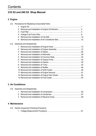
[2] Operating principles 1) Hydraulic motor section
As the high-pressure oil passes through the valve plate (1), intake side port (a) and flows into the cylinder, the hydraulic pressure works on the piston and a force F is generated in the axial direction.
See the figure below. This force F is divided into 2 vectors through the shoe (2) - the force F1 perpendicular to the swage plate (3) and the force perpendicular to the shaft. This force F2 is transmitted to the cylinder block (4) via the piston, generating a rotational couple around the output shaft.
Nine pistons are arrayed at evenly spaced intervals in the cylinder block. Rotary torque is transmitted to the output shaft by multiple pistons sequentially linked with the high-pressure oil intake side port. As the oil in and out directions are reversed, the rotation of the output shaft also reverses. The theoretical output torque [Nm] is given by the following equation.
p: Effective differential pressure [MPa] q: 1Capacity per rotation [cm3]
T = p × q 2π
Figure 2. Motor section operation explanation diagram
2) Valve casing section 2)-1 Anti-cavitation check valve section
The system that uses this type of motor does not have a valve with a counter-balance function. Thus, the motor is sometimes forced to rotate more times than the quantity of oil fed usually allows it.
In order to prevent cavitation due to insufficient oil, a check valve is provided to take in the oil shortfall.
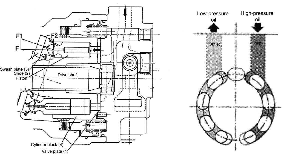
3) Brake section
The cylinder (111) is coupled with the drive shaft (101) by the gear. And circumferential rotation of the separator plate (743) is constrained by the arc groove being cut on the casing (301).
As the friction plate (742), which is gear coupled to the cylinder outer circumference section, is pressed to the casing (301) by the brake spring (712) via the separator (743) and the brake piston (702), frictional force is generated between the friction plate and casing and between the separator plate and the brake piston. This frictional force constrains the drive shaft, applying the braked.
The frictional force on the other hand, applies brake release pressure to the oil chamber being formed between the brake piston and the casing. And if the hydraulic pressure overcomes the spring force, the brake piston is moved, eliminating the force pressing the friction plate against the casing and, thus, releasing the brake.
Figure 3. Hydraulic circuit diagram
Spring force
Hydraulic pressure
*1
*1 Oil chamber
Figure 4. Brake hydraulic oil
4. Usage Precautions [1] Inspection Check the followings before installing a new motor. 1)Check the motor for damage during transportation and missing parts. 2)Check respective fastening portions for looseness. 3)Check the cover for flanged surface and oil drain port for completeness. And also check the motor for intrusion of dust.
[2] Direction of rotation
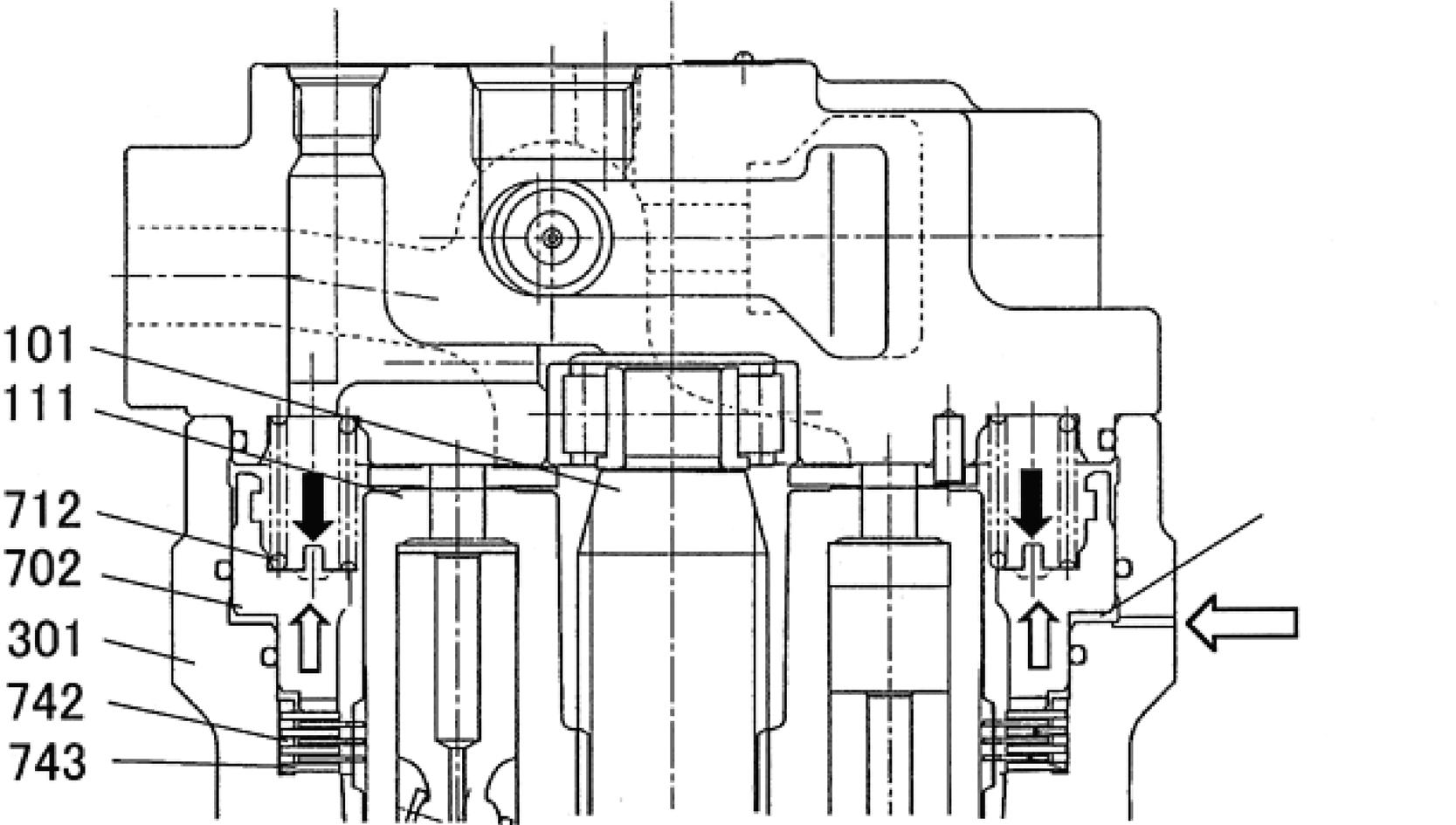
Figure 5 and Table 3 show the relation between the oil flow direction and shaft rotation direction. The direction of rotation depends on the tilt revolution direction of the casing slope face. Attentions must be paid to the tilt rotation direction. This direction is identifiable from the shape of the casing (concave portion) and the direction of the flange.
Table 3
Forward rotation Reverse rotation (Mis added to the end of the type name) Layout of A and B ports
Figure 5. Difference in casing resulting from tilt rotation direction (Casing in this figure is not provided with the reverse prevention valve)
Forward rotation
Reverse rotation (M is added to the end of the type name) Inlet Outlet Rotation Direction Viewed from Shaft Side
A B Right rotation (Clockwise direction)
B A Left rotation (Counterclockwise direction)
[3] Load at shaft end
Make sure radial and thrust load are not applied to the motor shaft end.
[4] Hydraulic oil and temperature range 1)Oil Type
The oil used should be mineral type hydraulic oil with a high viscosity index that has been added with extreme-pressure additives, foam inhibitor, antioxidants, and anti-corrosives. 2)Optimum Viscosity and Temperature of Hydraulic Oil (Figure 6)
The oil is usable in the viscosity range of 10 - 1000 cst. It is, however, recommended that oil in the range of 10 - 200 cs be used in order to ensure the optimum efficiency.
The temperature range is limited to -25°C to 100°C by the oil and O-ring used. Use of the oil at a temperature of 60°C or below is recommended in order to avoid potential deterioration of the hydraulic oil and seals.
3)Non-mineral Oil Type Hydraulic Oil
When use of hydraulic oil of either ester phosphate, water-glycol or fatty ester types is planned, contact us before using it.
[5] On filter
Intrusion of fine grains of soil or metal powers into the oil accelerates friction on the sliding surface and sometimes causes sticking and seizing. It is, therefore necessary to prevent intrusion of such foreign substances, and at the same time, to provide a 10-micron filter in the circuit.
Contamination should be Rank 9 or below in the NAS rank and 2 - 4 mmg/100 cc or below in the millipore pollution level.
Viscosity cSt Lower limit of temperature Higher limit of viscosity

Optimum use range
Lower limit of viscosity Higher limit of temperature
Figure 6. Optimum viscosity range and temperature range
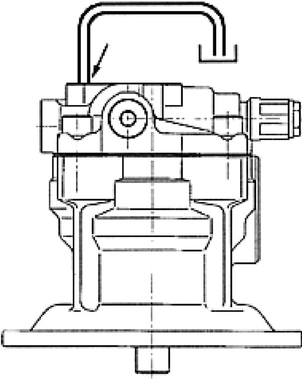
[6] Installation and piping 1)Install the motor, as a general rule, in such a way that its shaft comes to the bottom. 2)Make sure the centering with the driven part is precise. Make sure the displacement at the center is a maximum of 0.05 mm. 3)For the tightening torque to be used for installing the motor to the bracket, reference the dimensional outline drawing. 4)Make sure to constantly fill the casing with oil. The motor draining position must be set in such a way that the casing is filled with oil. See Figure 7.
5)Pressure in the casing is allowed up to a maximum of 0.3 MPa. Normally, however, it should be set to 0.2 MPa or below. 6)The pipe must be sufficiently acid washed and flushed. 7)The piping work should not apply extra force to the pipe. 8)The size of the drain pipe must be thicker than the motor port size and it must be routed as short as possible.
[7] Filling of oil and air bleeding 1)Before operating the motor, be sure to fill up the casing with oil from the oil drain port. High-speed sliding parts such as the bearing, piston/shoe and spherical bushing are provided in the motor. Problems such as seizing and damage can occur on these parts if the casing is not filled with oil. Thus, it is crucial to fill up the casing with oil. Volume of necessary oil 1000 cc 2)Bleed air completely from the circuit and motor. Otherwise, malfunctioning or damage can occur on them.
[8] Precautions for starting the operation 1)Make sure necessary piping is completed. 2)Make sure the rotating direction is correct. 3)Make sure the motor is completely free from oil leakages. 4)Make sure the motor is free from significant vibrations during operation or when the direction selector valve is operated. 5)Make sure the oil temperature does not rise abnormally during operation of a limited duration. 6)Make sure the pressure is not substantially deviating from the planned value.
*1
*1 Oil drain port
Figure 7. Example of correct drain piping (The casing in the figure is not provided with the reverse prevention valve.)
5. Cause of Problem and Solution [1] General cautions The following describes the corrective actions that are required to be taken if abnormality is recognized while operating the hydraulic motor. The following lists the general cautions. 1)Points to consider before taking actions Before proceeding to troubleshooting, try to remember whether a similar event has occurred before. Think again if the motor is really the cause. 2)Pay attention to dust. Wear is often caused by dust. Thus, reasonable care must be exercised during disassembly to prevent intrusion of dust. 3)Handling of parts Parts are precision-finished. Exercise care when handling them so that they are not damaged. 4)Care must be exercised in the corrective actions so as not to damage the surface of the O-rings and gaskets. It is recommended that O-rings are replaced when disassembling the motor.
[2] Procedure for inspecting motor unit problems
It is very difficult to locate the cause of a problem in the hydraulic circuit. Check the following items to determine whether or not the motor is actually responsible for the trouble. 1)Inspecting oil in the casing
Remove the drain plug and check hydraulic oil in the casing. If a large quantity of metal powder is contained in the oil, failure on the internal parts of the motor should be suspected. 2)Presence/absence of abnormal sounds
Check the motor unit for any abnormal sounds. 3)Measure pressure of respective components.
Do not rush into the overhaul inspection but measure pressure of the respective components first to locate the failed section. 4)Measurement draining volume from the motor i)Lock the swing and apply pressurized oil to the motor. In this case, if the draining volume measured is approximately 30 L/min. or less, the motor should be considered to be normal. ii)And the motor is also considered normal if the draining volume during the constant swing is 2 L/ min. or less.
[3] Mode of failure and corresponding corrective measures 1)Hydraulic motor does not rotate.
Phenomena Cause Measures Taken Pressure does not rise. 1.Safety valve in the path is not correctly set. 1.Set it to the correct value.
Pressure rise is available 2.Malfunctioning of relief valve (1) Sticking of plunger (2) Clogging on plunger 2.(1) Repair or replace the stick section (2) Disassemble and clean
3.Defective plunger seat 3.Check the seat and replace it if damaged. 1Overload 1Eliminate the load 2.Seizing on the moving part 2.Inspect and repair piston/shoe and cylinder/valve plate.
3.Release pressure is not working on brake. 3.Inspect and repair the circuit.
4.Piston is stuck to brake. 4.Disassemble and Inspect 5.Brake releasing spool is stuck. 5.Disassemble and inspect 6.Friction plate is seized. 6.Disassemble and inspect Replace the seized plate.
3)Revolution does not reach the specified value.
4)Hydraulic motor does not rotate
Phenomena Cause Measures Taken Rotating direction is the opposite to the specified direction 1.Motor rotating direction is opposite 1.Reference Figure 5 and assemble motor correctly. 2.Inlet and outlet of the pipe are set 2.Install pipe correctly
inversely.
Phenomena Cause Measures Taken Revolution does not reach the specified value. 1.Volume of incoming oil is insufficient. 1.Check pump discharge volume as well as the state of the circuit to the motor.
2.Leakage of abnormally large volumes is induced by high oil temperature. 2.Reduce the oil temperature.
3.Friction or damage of sliding parts 3.Replace the failed sliding part.
Phenomena Cause Measures Taken Brake torque tends to go short. 1.Wear on the friction plate. 1.Disassemble and inspect the plate. Replace it if wear is more severe than the level allowed in the standard. 2.Brake piston is stuck. 2.Disassemble and inspect 3.Brake release pressure is not able to be relieved. 3.Inspect and repair the circuit. 4.Brake releasing spool is stuck. 4.Disassemble and inspect 5.The spline of the friction plate is damaged. 5.Disassemble and inspect the plate. Replace a damaged spline.
5)Significant slippage is observed on the hydraulic motor.
Inspect the draining volume from the hydraulic motor. If it is around 500 cc/min., the motor is free from problems.
6)Oil leakage i) Oil leakage from oil seal
ii) Oil leakage from the alignment surface
Phenomena Cause Measures Taken Significant slippage results as the external motor driving force is turned on. 1.Malfunctioning of relief valve Same as 1) above. 1.Replace the valve. Same as 1) above. 2.Defective plunger seat 2.Replace the seat.
Phenomena Cause Measures Taken Oil leakage from oil seal 1.Lip is damaged by dust being bitten. 1.Replace oil seal. 2.Shaft is damaged or worn. 2.Move the position of lip and shaft or replace the shaft. 3.Abnormally high pressure inside the casing flipped the lip up. 3.Repair drain pipe if clogged. 4.Shaft is rusted. 4.Disassemble and repair
Phenomena Cause Measures Taken Oil leakage from the alignment surface 1.O-ring is not fitted. 1.Insert and assemble O-ring correctly. 2.O-ring is damaged. 2.Replace the O-ring. 3.Sealing surface is damaged. 3.Disassemble and repair the sealing surface. 4.Bolt is loose or damaged. 4.Tighten the bolt to the specified torque or replace it.
6. Assembly and Disassembly [1] Bolt tightening torque Table 1 shows the tightening torque for the bolts used on the motor. When assembling the motor, tighten the bolts securely referencing Table 1.
Table 1.
Screw Size Name Tightening Torque N•m Applicable Part Code
M 20 Hexagon socket head bolt 431 401
M 33 × P 1.5 Relief valve 177 051
M 36 × P 1.5 ROMH plug 539 469 PF1/4 ROH plug 36 467 If the part in hand is not consistent with the above part code, reference the assembly cross-section diagram.
[2] Tools for assembly and disassembly
Table 2 and Table 3 list the tools needed for assembly and disassembly. Bolt and plugs used depend on the given motor type. Check the type beforehand to prepare the necessary tools.
Table 2. Wrenches
Name Size Width Across Flats Applicable Part Code Tool
Hexagon socket head bolt M 20 17 401 Hexagon bar wrench
Relief valve M 33 × P 1.5 41 051 Hexagon wrench and socket wrench
ROMH plug M 36 × P 1.5 17 469 Hexagon bar wrench ROH plug PF1/4 6 467 Hexagon bar wrench If the part in hand is not consistent with the above plugs and bolts, reference the assembly cross-section diagram.
Table 3. Others
Tool Specification Dimension
Screwdriver Medium-sized flathead screwdriver × 2
Steel rod About 10 × 8 × 200
Hammer Plastic hammer Hammer 1 each
Torque wrench Torque adjustment range •For 5 - 10 N•m •For 10 - 45 N•m •For 40 - 275 N•m •For 75 - 550 N•m
Slide hammer bearing puller
Brake piston pulling jig See the next page
*4
*1 Brake piston pulling jig *2 Brake piston *3 Casing *4 Through hole
*1
*2
*3
Specialized brake piston removal jig
[3] Disassembly procedure
Disassemble the motor in the following order. The number in parentheses shown after the part name indicates the code used in the structural diagram.
1)Wrap the wire rope around the motor, lift it with a crane and wash it using white kerosene. After washing, dry the motor with compressed air. •Mask the ports using a piece of tape to prevent intrusion of foreign substances to the motor, and then wash away any deposited dirt and dust.
2)Drain the oil in the casing (301) through the drain plug.
3)Set the end of the driving shaft (101) downward and then place the motor on a bench that allows easier disassembly.
When disassembling, apply an alignment mark to the mating surface of the casing (301) and valve casing (303). •Select a clean place. Spread a rubber plate of piece of cloth on the disassembling bench to protect the parts from damage.
4)Loosen the relief valve (051) and remove it from the valve casing (303). •Loosening the relief valve inevitably damage the O-ring. Thus, the O-ring must be replaced with a new one.
5)Remove the ROMH plug (469) from the valve casing (303) and then remove the spring (355) and plunger (351). •Care must be exercised in this operation to protect the plunger seat from damage.
6)Loosen the hexagon socket head bolt (401) to remove the valve casing (303) from the casing (301). (As the bolt is removed, force of the brake spring (712) lifts the valve casing from the casing.)
Remove the valve plate (131) from the valve casing (303). •Care must be exercised in this operation so the valve plate is not dropped from the valve casing. (The valve plate is sometimes provided on the cylinder side.)
When prying the alignment surface using a screwdriver, reasonable care must be exercised so as not to damage the surface.
8)Using the jig, remove the brake piston (702) from the casing (301). •Hitch the toe of the jig on the side face of the brake piston and pull it up straight.
9)Re-place the motor horizontally to remove the cylinder (111) from the drive shaft (101). Then remove the piston (121), holder plate (123), plate spring (114) and shoe plate (124). •Care must be exercised so as not to damage the sliding surface of the cylinder and shoe.
If the shoe plate is unable to be removed, remove it using work step 12).
10)Remove the friction plate (742) and separator plate (743) from the casing (301).
11)Remove the drive shaft (101) and shoe plate (124). •The oil seal will inevitably be damaged by the spline when removing the drive shaft.
To avoid the above problem, wrap vinyl tape or similar material around the drive shaft spline.
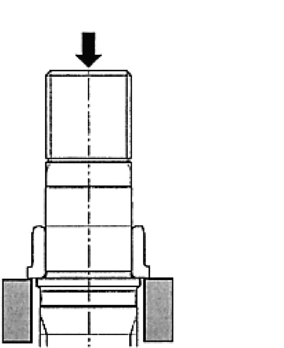
12)Implement the following work as needed. (1)Remove the inner race of the cylindrical roller bearing (443) from the drive shaft (101) using the press. •It is safe to strike the inner race of the cylindrical roller bearing with a steel rod, however care must be exercised so as to strike it uniformly so that the bearing is not damaged. It is prohibited to reuse a once removed bearing.
(2)Remove the outer race of the cylindrical roller bearing (443) from the drive shaft (301) by striking it lightly from the housing side with a steel rod. •Do not reuse a bearing that has already been removed.
*1
*2
*3
(3) Using the slide hammer bearing puller, remove the cylindrical roller bearing (444) from the valve casing (303). •It is prohibited to reuse a once removed bearing.
The above completes the disassembly. Check respective components for any problems.
*1 Press *2 Drive shaft *3 Hitch the bench of the press on the inner race.
[4] Assembly procedure
The assembly is carried out in the reverse order of the disassembly procedure. However, follow the precautions below. (1)Be sure to repair any parts damaged during disassembly, and prepare replacement parts in advance. (2)Clean the parts sufficiently with cleaning liquid and then dry them using compressed air. (3)Be sure to coat sliding parts and bearings with clean hydraulic oil before assembling. (4)It is necessary, as a general rule, to replace the sealed portion of O-rings and oil seals. (5)When tightening the mounting bolts and plugs, tighten them to the torque listed in Table 1 by use of the torque wrench.
The following describes the assembly procedure.
1)Place the casing (301) on an appropriate bench in such a way that the valve casing (303) side comes to the top. 2)(This work step is required only when the cylindrical roller bearing is remove.)
Thermal-insert the inner race of the cylindrical roller bearing (443) to the drive shaft (101). •Pay attention to the direction of the collar of the cylindrical roller bearing.
*1
3)Using the jig, insert the oil seal (491) to the casing (301). •Pay attention to the direction of the oil seal. (Refer to the assembly cross-section diagram)
*1 Output shaft side
4)Assemble the outer race of the cylindrical roller bearing (443) to the casing (301) by hammering it lightly with a steel rod.
5)Install the rive shaft (101) to the casing (301). •Care must be exercised during installation so as not to damage the oil seal lip.
It is advisable to wrap vinyl tape around the shaft spline section.
6)Place the casing (301) horizontally and then insert the shoe plate (124). •The side with the wider chamfering area on the shoe plate is assembled to the casing.
In order to prevent detachment, it is advisable to coat the alignment surface with a small amount grease.
7)Set the holder plate (123) and plate spring (114), then set the piston sub-assembly (121,122).
8)Assemble the piston sub-assembly (121, 122) being set on the holder plate (123) to the cylinder (111) and then insert them into the casing while aligning them with the spline of the drive shaft (101).
9)Re-set the casing (301) in such a way that the oil seal (491) faces downwards and then assemble separator plates (743) and friction plates (742) alternately to the casing in this order. 4 separator plates and 3 friction plates are assembled.
10)Install O-rings (706) and (707) on the casing (301). •It is advisable to coat the O-rings with a small amount of grease to protect them from being cut off as the brake piston is inserted.
13)(This work step is required only when the cylindrical roller bearing (444) has been removed)
Insert the outer race of the cylindrical roller baring (444) to the valve casing (303) hammering the outer race lightly with a steel rod. •Hammer the perimeter of the outer race evenly until it is stopped at the stepped section of the valve casing.
14)Assemble the valve plate (131) at the valve casing (303) and then install the O-ring (472) onto them. •Coat the mating face of the valve plate with a small amount of grease. (To prevent detachment)
15)Install the valve casing (303) on the casing (301) and then tighten them with the hexagon socket head bolt (401). •Pay attention to the mounting direction of the valve casing. (Refer to the dimensional outline drawing)
Exercise care to prevent the valve plate from detaching.
Be sure to prevent the brake spring from falling over.
The hexagon socket head bolt must be uniformly tightened.
16)Insert the plunger (351) and spring (355) into the valve casing (303) and then fasten the ROMH plug (469) installed with the Oring (488) to the valve casing (303). •Make sure that the plunger moves smoothly.
The above completes the assembly.
7. Maintenance Procedure [1] Friction parts replacement standard If wear on the following parts is more severe than the value permitted in the standard, applicable parts must be repaired or readjusted. The above, however, is not applicable when serious external damage has been recognized.
Table 4. Part Replacement Standard
Item Standard Dimension (mm) Recommended Value for Replacement (mm) Measures Taken
Clearance between piston and cylinder bore (D-d) Play in the piston and shoe caulking section (δ) Shoe thickness (t) 0.028 0.058
0 0.3
Replace piston or cylinder
Replace piston and shoe assembly.
5.5 5.3 Replace piston and shoe assembly.
Friction plate thickness 2.0 1.6 Replace the plate.
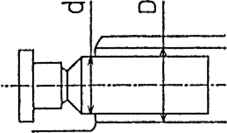
Clearance (D-d) Play in piston and shoe (δ)
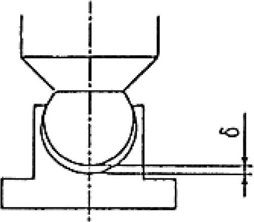
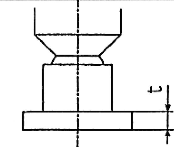
Shoe thickness (t)
[2] Sliding surface repairing standard
If the sliding surface of respective components has become roughened beyond the level permitted in the standard, they must be repaired or replaced.
Table 5. Siding Surface Repairing Standard
Note1.Surface roughness of each sliding surface must be repaired until it is below the standard surface roughness through the lapping process. 2.If spherical sliding section of the plate spring or cylinder has become roughened, the part must be replaced as a set.
Part name Standard Surface Roughness
Shoes 0.8-Z (Ra=0.2) (Lapping) Shoe plate 0.4-Z (Ra=0.1) (Lapping)
Cylinder 1.6-Z (Ra=0.4) (Lapping) Valve plate 0.8-Z (Ra=0.2) (Lapping) Surface Roughness that Requires Repair
3-Z (Ra=0.8)
3-Z (Ra=0.8)
12.5-Z (Ra=3.2)
6.3-Z (Ra=1.6)
Explanation of Relief Valve Operation (Relief valve model: KRD22EK10)
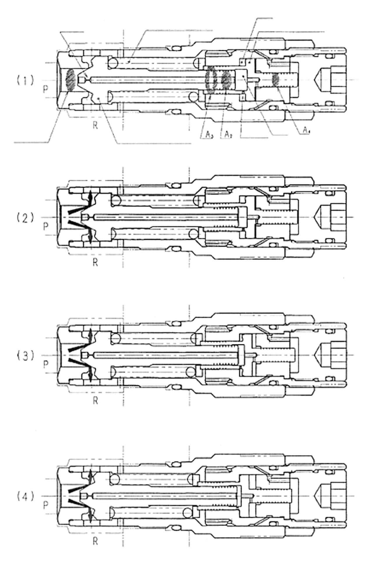
The following outlines the case where the valve is pressurized by the P port tank pressure. Initially the P and R ports are set to the tank pressure as shown in Figure 1-(1). The relief valve starts operating at a pressure level at which the hydraulic pressure force to be determined by the product of pressurized area A1 the plunger (301) and pressure P balances with the hydraulic pressure force to be determined by the product of load FSP of the spring (321), pressurized are A2 on the plunger (301) and pressure of g chamber Pg. After that, the g chamber pressure rises and the piston 1 (302) starts its stroke. Accompanying this movement, the load on the spring (321) increases. Through the above operation, relief pressure P is controlled to rise from P1 to PS in the pressure rise time t1. The following explains this process using the relationship between the moving parts shown in Figures 1-(2) - (4) and the relief pressure.
(1) The state shown in Figure1-(2)
As the relief valve P port is pressurized, pressure is generated in the g chamber via the metering valve m of the plunger (301).
If the hydraulic pressure operating on the plunger (301) increases up to a level where it balances load FSP of the spring (321), the relief valve starts the relief operation at pressure P1.
The relationship at this point is expressed by the following equation. P1 × A1 = FSP1 + Pg1 × A2 FSP1: Initially set load of the spring (321)
(2) The state shown in Figure 1-(3)
The g chamber pressure operates on pressurized areas A3-A4 of the piston (1) (302). As this hydraulic pressure force outgrows the load on the spring (321), piston 1 starts its leftward movement.
At this time, piston 1 moves leftward discharging oil in h chamber, which is formed between the piston 1 and adjusting plug (401), to g chamber via the metering valve n provided on the piston (302). Thus, chamber h functions as a damping chamber.
Through this, the spring load gradually increases and relief pressure P also increases smoothly until piston 1 reaches the adjusting plug end section.
(3) The state shown in Figure 1-(4)
As the piston 1 (302) reaches the adjusting plug (401) end section, its leftward movement is stopped there. Thus the constant relief state is turned on and relief pressure is held at P2.
Through the processes (1) - (4) above, the relief pressure varies as shown in Figure 2.
2. Explanation of Operation of Relief Valve under Depressurization
The following describes the case where the P port pressure is decreased.
As pressure to P port is removed, pressure in g chamber also decreases to the tank pressure.
Because of the above change in pressure, the currently opened plunger (301) is moved leftward until it is seated on the seat (341). At the same time, the piston (1) (302) also is moved rightward by spring (321), resulting in the restoration of the state shown in Figure 1-(1).
Seat (341) Metering valve m Spring (321) h chamber
Piston1(302) Adjusting blug (401)
Pressurized area A1 Plunger (301)
Metering valve n
g chamber
Figure 1. Relief valve operation explanation diagram
Metering Spring (321) h
Piston1(302)
Pressurized Plunger (301) Metering g
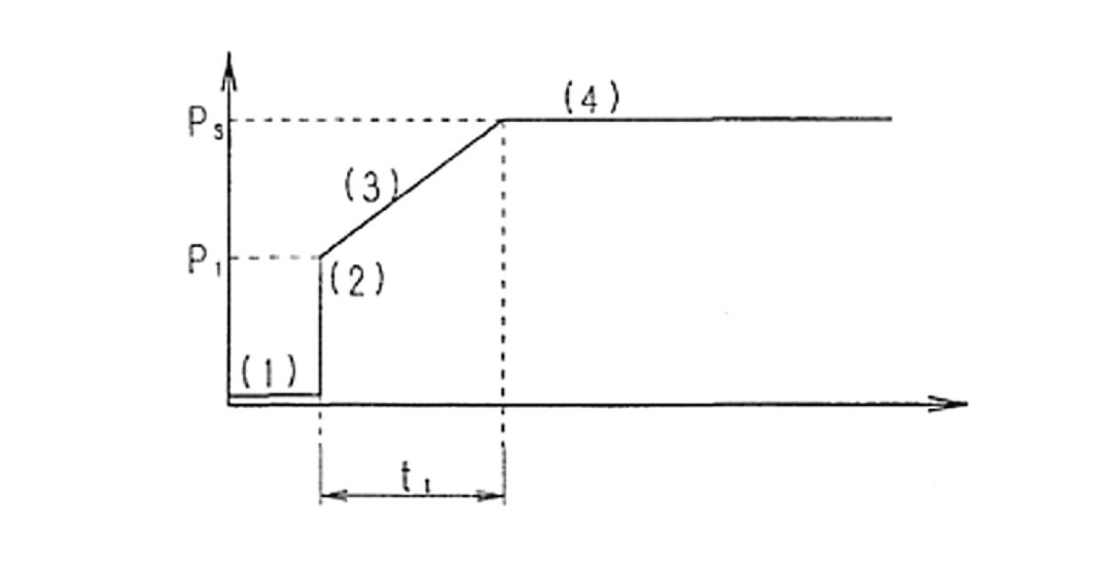
Figure 2. Boosted pressure characteristics