9 minute read
2Assembly and Disassembly Procedures of Pump Main Unit


2 Assembly and Disassembly Procedures of Pump Main Unit
1. Tools
The table below shows the tools required for the assembly and disassembly of the K3V pump. The bolts and plugs may vary by pump type.
B
Tool name and dimensions Required tools are indicated with Hydraulic pump type Part name
Name B K3V63 K5V80 K3V112 K5V140 K3V140/180 K5V200
Hexagon socket head bolt PT mounted valve (PT screw)
PO plug (PF screw)
Hexagon socket head stop screw
Hexagon bar wrench 2 - - - M4 2.5 - - - M5 3 - - - M6 4 M5 BP-1/16 - M8 5 M6 BP-1/8 - M10 6 M8 BP-1/4 PO-1/4 M12 M14 8 M10 BP-3/8 PO-3/8 M16 M18 10 M12 BP-1/2 PO-1/2 M20 12 M14 - - 14 M16 M18 BP-3/4 PO-3/4 17 M20 M22 BP-1 PO-1,11/4,11/2 19 M24 M27 - - 21 - - - 22 M30 - PO-2 -
Closed wrench Socket wrench Double-head (single-head) wrench
19 M12 M12 VP-1/4 22 - - VP-3/8 24 M16 M16 - 27 M18 M18 VP-1/2 30 M20 M20 - 36 - - VP-3/4 41 - - VP-1 50 - - VP-11/4 55 - - VP-11/2 Monkey wrench - Medium-sized × 1 Screwdriver - Medium-sized flathead screwdriver × 2 Hammer - Plastic hammer × 1 Pliers - For stop ring, TSR-160 Steel rod - Key material steel rod, 10 × 8 × 200 Torque wrench - With adjustable specified torque tightening
2. Disassembly Procedure
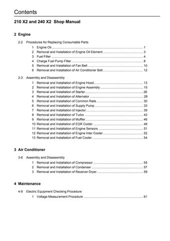
Read the entire section below on the disassembly procedure, and follow the procedure for disassembling the pump. The numbers in parentheses on the rear of each part correspond to the part numbers in Figure 3. Pump assembly cross-section diagram.
[1] Select the location for disassembling the pump. •Find a clean location to disassemble the pump. •Place a rubber plate or cloth on the work table so as not to damage the parts. [2] Use cleaning oil to remove any dirt or rust from the surface of the pump. [3] Remove the oil drain port plug (468) and drain the oil from the pump casing (271). •Remove the plugs from both the front and rear pumps. [4] Remove the hexagon socket head bolts (412, 413) and the regulator, and then remove the hexagon socket head bolt (414) and the cover (326).
Loosen the 3 hexagon socket head bolts (M6-60) securing the electromagnetic proportional pressure reducing valve and casing subassembly (079), and remove the electromagnetic proportional pressure reducing valve and casing subassembly. •See the Explanation of Regulator Operation for how to disassemble the regulator.
[5] Loosen the flange socket (435), and remove the gear pump (04).
[6] Loosen the hexagon socket head bolt (401) that fastens together the swash plate support board (251), pump casing (271), and valve block (312).
[7] Face down the pump regulator installation surface horizontally on the work table, and separate the pump casing (271) and valve block (312). •When facing down the regulator installation surface, be sure to place a rubber plate or similar material on the work table so as not to damage the regulator installation surface. •When separating the pump casing and valve block, remove the 1st gear (116) at the same time.
[8] Remove the cylinder (141) straight out from the pump casing (271) toward the drive shaft (111, 113), and remove the piston subassembly (151, 152), holder plate (153), spherical bush (156), and cylinder spring (157) at the same time. •Be careful not to damage the sliding surfaces of the cylinder, spherical bush, shoes, and swash plate.
[9] Remove the hexagon socket head bolt (406), and remove the seal cover (F) (261). •The seal cover (F) can be easily removed by inserting a bolt into the hole (M6 tap) on the seal cover (F) and pulling it out. •The seal cover (F) has an oil seal, so be careful not to damage the oil seal when removing the seal cover (F).
[10]Tap the rear of the drive shaft (111, 113), and separate it from the swash plate support board (251).
[11]Remove the shoe plate (211) and swash plate (212) from the pump casing (271).
[12]Tap the mounting flange section of the swash plate support board (251) on the pump casing side, and separate the swash plate support board and the pump casing. [13]Remove the valve plate (313, 314) from the valve block (312). •This can also be removed in Step [7].
[14]If necessary, remove the stopper (L) (534), stopper (S) (535), servo piston (532), and tilting pin (531) from the pump casing (271), and remove the needle bearing (124) from the valve block (312). •To avoid damaging the head of the tilting pin, use a jig when removing the tilting pin. •The section where the tilting pin and servo piston are bonded is coated with Locktite, so be careful not to damage the servo piston. •Do not remove the needle bearing unless it is at the end of its service life. •Do not loosen the hexagon nut of the valve block or swash plate support board. This changes the flow volume setting.
3. Assembly Procedure
The assembly procedure is the reverse of the disassembly procedure. However, follow the precautions below. 1) Be sure to repair any parts damaged during disassembly, and prepare replacement parts in advance. 2) Thoroughly clean all parts with cleaning oil and air blow before assembling. 3) Be sure to coat sliding parts and bearings with clean hydraulic oil before assembling. 4) As a rule, replace all O-rings, oil seals, and other seal parts with new parts. 5) Use a torque wrench to tighten all installation bolts and plugs to the torque specified in the
Maintenance Standards. 6) Be careful not to mix up the pump parts for the front and rear of the tandem pump.
[1] Install the pump casing (271) by tapping the swash plate support board (251) with a hammer. •If the servo piston, tilting pin, stopper (L), and stopper (S) have been removed, assemble these parts in the pump casing in advance. •To avoid damaging the tilting pin head and feedback pin, use a jig when tightening the servo piston and tilting pin. Also be sure to coat the screw sections with Locktite (moderate strength).
[2] Attach the shoe plate (211) to the swash plate (212). Face down the regulator installation surface of the pump casing, insert the tilting bush of the swash plate into the tilting pin (531), and correctly mount the swash plate and shoe plate on the swash plate support board (251). •Use the tips of both fingers to check that swash plate moves smoothly. •Coat the swash plate, swash plate support board, and all sliding sections with grease for easier installation of the drive shaft. •Be careful not to damage the sliding surface of the shoe plate.
[3] Install the drive shaft (111, 113) with attached cylinder roller bearing (123), bearing spacer (127), and stop spring (824) to the swash plate support board (251).
[4] Attach the seal cover (F) (261) to the pump casing (271), and secure with the hexagon socket head bolt (406). •Lightly coat the oil seal of the seal cover (F) with grease. •Attach the oil seal while being careful not to damage it.
[5] Assemble the piston cylinder subassembly [cylinder (141), piston subassembly (151, 152), holder plate (153), spherical bush (156), spacer (158), cylinder spring (157)], and insert it into the pump casing in alignment with the phase of the spherical bush and cylinder spline.
[6] Install into the valve block (312) while aligning the valve plate (313, 314) with the pin (885). •Be careful not to mistake the intake and discharge directions of the valve plate.
[7] Face down the pump regulator installation surface horizontally on the work table, and install the pump casing (271) and valve block (312). •When facing down the regulator installation surface, be sure to place a rubber plate or similar material on the work table so as not to damage the regulator installation surface. •Install the valve block in the correct direction. (Install the valve block with the regulator facing up and the suction flange facing to the right when looking at the valve block from the front.) •When installing the pump casing and valve block, install the 1st gear at the same time.
[8] Tighten the flange socket (435), and install the gear pump (04).
[9] Tighten the valve block (312) and pump casing (271) with the hexagon socket head bolt (401). •It is easier to assemble when starting with the rear pump.
[10]Tighten the hexagon socket head bolt (414) to the valve block (312), and install the cover (326).
[11]Insert the feedback pin of the tilting pin into the feedback lever of the regulator, install the regulator, and tighten the hexagon socket head bolts (412, 413). •Install the regulator, making sure not to mistake the front and the rear of the regulator. [12]Tighten the 3 hexagon socket head bolts (M6-60) to the valve block (312), and install the electromagnetic proportional pressure reducing valve and casing subassembly (079). [13]Attach the oil drain port plug (467) to finish assembly.
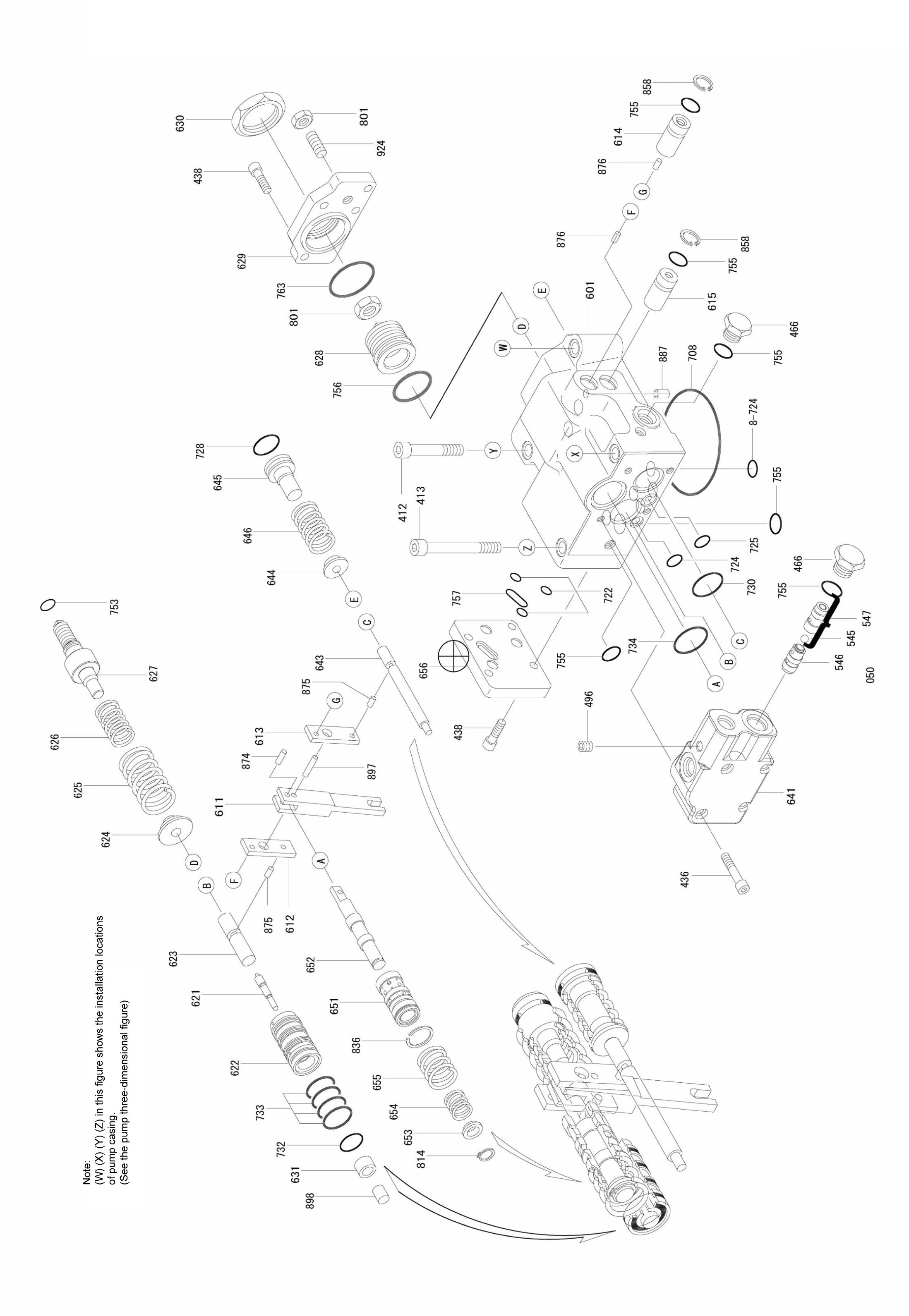
Figure 1. Pump parts breakdown
Pump main unit: Maintenance standards
1. Standards for Replacing Worn Parts
If any part exceeds the standard values below and is worn, replace or readjust that part. If, however, the appearance of the part shows significant damage, replace that part.
Part name and inspection item Standard dimensions/recommended replacement value Hydraulic pump type
K3V63, K5V80 K3V112 K5V140, K3V140 K5V200, K3V180 Measure
Piston to cylinder bore clearance (D-d) 0.028 / 0.056 0.039 / 0.067 0.043 / 0.070 0.0375 / 0.078 Replace piston or cylinder Piston, shoes, and caulking section backlash (δ) 0 - 0.1 / 0.3 0 - 0.1 / 0.3 0 - 0.1 / 0.3 0 - 0.1 / 0.35
Replace piston and shoe assembly
Shoe thickness (t) 3.9 / 3.7 4.9 / 4.7 5.4 / 5.0 5.4 / 5.0
Replace piston and shoe assembly
Free height of cylinder spring (L) Assembled height of holder plate and spherical bush (H-h) Cylinder over-pindiameter (spline in cylinder) Spline in spherical bush 31.3 / 30.2 41.1 / 40.3 47.9 / 47.1 40.9 / 40.1 Replace cylinder spring
19.0 / 18.2 23.0 / 22.0 23.8 / 22.8 23.8 / 22.8
Replace holder plate or spherical bush
35.17 (φ5)/35.57
Replace cylinder and spherical bush
d D
Piston to cylinder bore clearance (D-d)
L
Free heigh of cylinder spring (L)
t δ
Piston, shoes, and caulking section backlash ( ) Shoe thickness (t)
h H
Assembled height of holder plate and spherical bush (H-h)
2. Standards for Replacing the Cylinder, Valve Plate, and Swash Plate (shoe plate)
3. Tightening Torque
Valve plate (sliding section) Swash plate (shoe plate section) Cylinder (sliding section) Surface roughness Surface roughness requiring repair 3-Z
Standard surface roughness (repair value) 0.4Z or lower (lapping)
B
Part name Size Tightening torque (N•m)
Hexagon socket head bolt (material SCM435) M5 M6 M8 M10 M12 M14 M16 M18 M20 6.9 12 29 57 98 160 240 330 430
PT plug (material S45C) Note: Wrap the seal tape 1.5 - 2 times.
PO plug (material S45C) RC1/16 RC1/8 RC1/4 RC3/8 RC1/2
G1/4 G1/2 G3/4 G1 G 1 1/4 G 1 1/2 6.9 10 17 34 49
29 98 150 190 260 270 Tool name (mm)
Hexagon bar wrench
Same as above
Same as above
Figure 2. Pump dimensional outline diagram
Figure 3. Pump assembly cross-section diagram