107 minute read
2Assembly and Disassembly of Travel Motor


2 Assembly and Disassembly of Travel Motor 1.Foreword
This manual provides instruction for maintenance of the swash plate-type piston motor with case rotation type reduction gear for the open circuit MAG-170VP-3800E series. This manual helps first-time users to understand maintenances issues as well as assists experienced users to review the swash plate-type piston motor with case rotation type reduction gear for the open circuit manufactured by KYB Co., Ltd. Read this maintenance procedures well and come to an understanding of its contents before beginning actual maintenance work. It is recommended that users keep this manual ready at hand during operation.
This maintenance procedures mainly consists of (1) the disassembling procedure, (2) maintenance standards (3) assembling procedure, and (4) post-assembly checking points for the MAG-170VP-3800E series, swash plate-type piston motor with case rotation type reduction gear for the open circuit.
MAG-170VP-3800E series, swash plate-type piston motor with case rotation type reduction gear for the open circuit produced by KYB Co., Ltd. is the actuator used in the hydraulic unit of the mother machine. Therefore, this maintenance procedures should be used along with the maintenance procedures of the mother machine. Always refer to the maintenance procedures of the mother machine when using this maintenance procedures.
2.For Safety Operation
Safety Cautions Be sure to follow the instructions below:
Warning
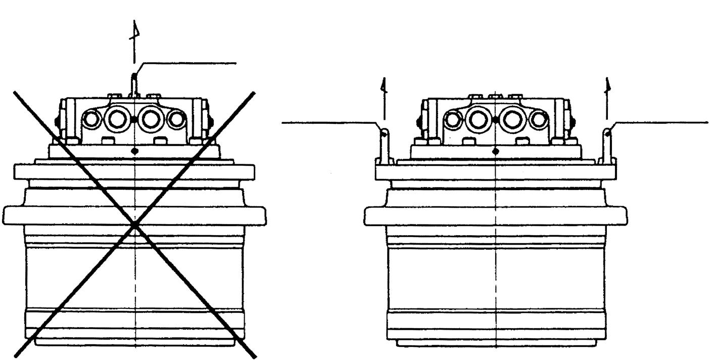
Never lift the motor by the tap on the base plate when transporting by crane. Doing so may cause the motor to fall, which may cause personal injury or damage to the machine.
Warning Always wear a helmet, safety shoes, gloves and protective goggles when disassembling the motor for transportation, installation, maintenance and inspection, etc.
Lifting prohibited Lifting recommended Eyebolt
Eyebolt Eyebolt
Safety Cautions Be sure to follow the instructions below:
Warning
Do not run the motor when the hydraulic oil level is low in the hydraulic tank (near the inlet), or when the hydraulic tank is empty. Doing so may cause air to enter the motor, and the motor may go out of control, which may cause personal injury or damage to the machine.
Inlet Hydraulic tank
Outlet
Warning
Do not run the motor when the pipe is empty.
Doing so may cause air to enter the motor, and the motor may go out of control, which may cause personal injury or damage to the machine.
Warning
Never remove the oil fill, oil discharge or oil check ports of the reduction gear lubricating oil within 1 hour after the motor has stopped. Doing so may cause high-temperature lubricating oil to squirt out and may cause burns. High-temperature lubricating oil will squirt out and may cause loss of eyesight if it gets into the eyes.
Safety Cautions Be sure to follow the instructions below:
Never remove the pressure detection port or oil drain port when the pipe is pressurized. Doing so may cause pressurized oil to squirt out and may cause loss of eyesight if it gets into the eyes. Always release the pressure inside the pipe to atmosphere level before removing.
Warning
Do not remove the cover from the reduction gear with the motor attached to the machine body. Doing so may cause your fingers or hands to get pinched causing injury.
Warning
Warning
Do not disassemble the motor with the motor attached to the machine body. Doing so may cause the machine to go out of control resulting in personal injury. Always remove the motor from the machine body before disassembling.
Safety Cautions Be sure to follow the instructions below:
Do not remove the spool from the double counter balance valve with the motor attached to the machine body. Doing so may cause the machine to go out of control causing personal injury or damage to the machine.
Warning
Never tamper with the relief valve adjuster. Doing so will change the set pressure of the relief valve, and the machine may go out of control causing personal injury or damage to the machine.
Warning
Safety Cautions Be sure to follow the instructions below:
Caution Do not run the motor beyond the specified range. Doing so may cause damage to the machine.
Never touch the motor within 1 hour after the motor has stopped. The motor surface is very hot as it has been operating. Touching the motor can cause burn injuries.
Caution
Never suddenly remove the oil fill, oil discharge or oil check port of the reduction gear. Doing so may cause the plug to pop out, causing injury. Align the ports to the specified positions, and slowly loosen the plugs, starting from the oil fill port on the top, to release the air inside the reduction gear.
Caution
Top Reduction gear lubricating oil Oil fill port
Reduction gear lubricating oil Oil check port Release air.
Loosen the oil fill port about 2 turns to release air inside the reduction gear.
Bottom Reduction gear lubricating oil Oil drain port Discharge oil.
Discharge oil while slowly loosening the discharge port plug.
Safety Cautions Be sure to follow the instructions below:
When connecting the pipe, make sure that the direction of hydraulic oil flow corresponds to that of the motor rotation. Failure to do so can reverse the motor rotation.
Caution Use specified hydraulic oil only. Otherwise, the machine may be damaged.
Caution Use specified hydraulic oil only. Otherwise, the machine may be damaged.
Caution Do not allow foreign matter to enter inside the motor. Otherwise, the machine will be damaged.
A direction (counterclockwise) C direction (clockwise)
Caution
Caution
Wait until the motor cools down before servicing or inspecting the motor.
3.Tools for Assembly and Disassembly
To disassemble or re-assemble a motor, user the tools listed below. [1]Standard tools
Table 1 shows the standard tools required for the disassembly and assembly of this motor.
Table 1. Standard Tools for Disassembly and Assembly
No. Name of the Tool Standard No. Manufacturer Name Model or Dimensions Applicable Part
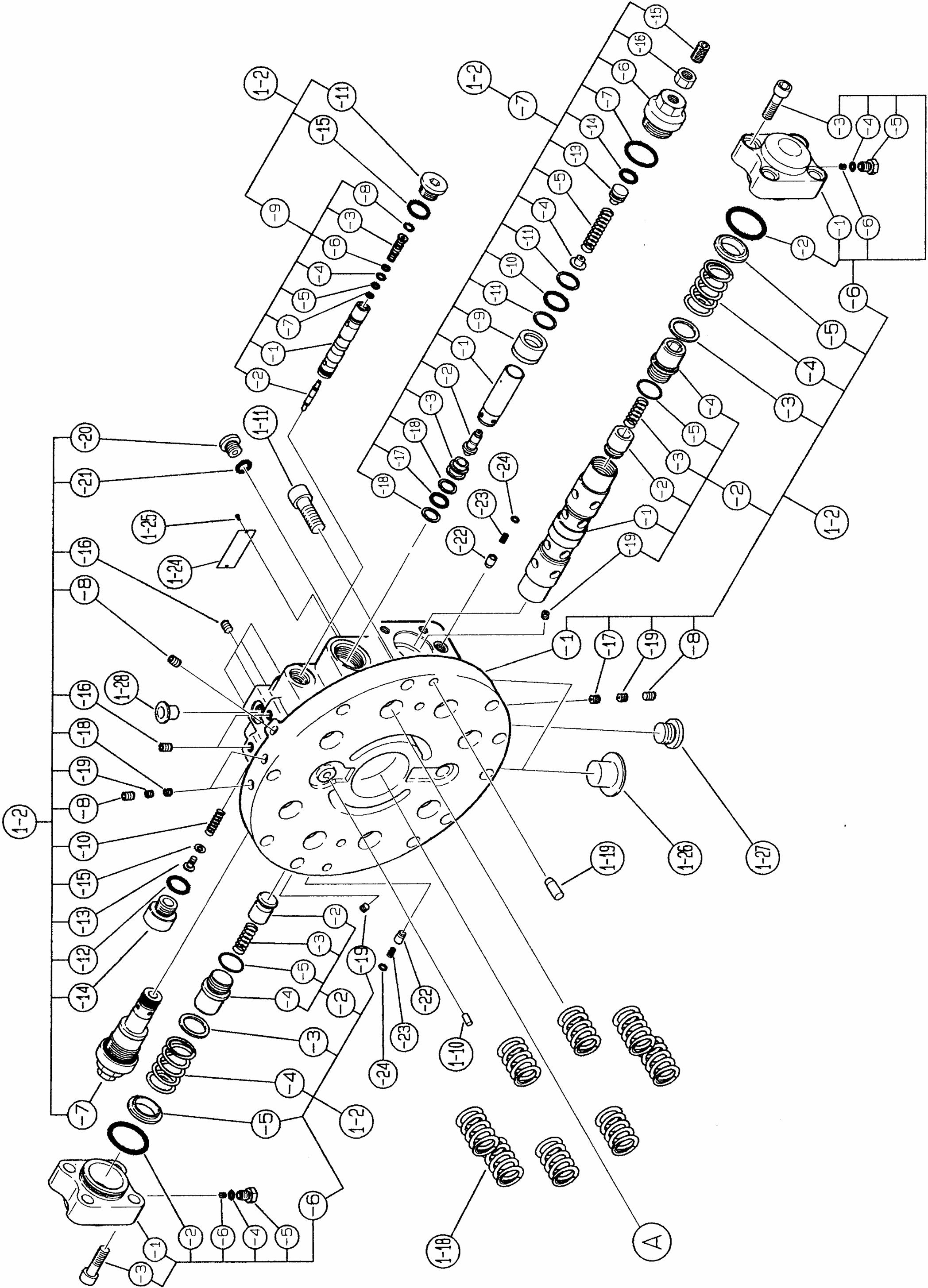
1 Preset-type torque wrench JIS B4650 Nominal size: 60 1-2-6-6, 1-2-17, -18, -19 2 Nominal size: 120 1-2-8 3 Nominal size: 230 1-2-6-5 4 Nominal size: 450 1-2-20 5 Nominal size: 900 24, 28 6 Nominal size: 1800 1-2-2-4, 1-2-6-3, 1-2-11, 1-214, 29 7 Nominal size: 2800 11 8 Nominal size: 4200 1-2-7 9 Nominal size: 5600 8, 14 10 Socket wrench Ratchet handle JIS B4641 11 Hexagon bit for socket wrench Width across flat: 2.5 1-2-6-6, 1-2-17, -18, -19 12 Width across flat: 4 1-2-8 13 Width across flat: 6 1-2-20 14 Width across flat: 8 28 15 Width across flat: 10 1-2-6-3, 1-2-11 16 Width across flat: 12 11, 29 17 Width across flat: 14 1-2-2-4, 1-2-6-5 18 T-shaped bit for torque wrench JASO F116-89 Size: T50 24 19 Size: T90 8, 14 20 Socket for socket wrench JIS B4636 Width across flat: 10 1-2-14 21 Width across flat: 27 1-2-7 22 Hexagon bar wrench JIS B4648 Width across flat: 2.5 1-2-6-6, 1-2-17, -18, -19 23 Width across flat: 4 1-2-8 24 Width across flat: 6 1-2-20 25 Width across flat: 8 28 26 Width across flat: 10 1-2-6-3, 1-2-11 27 Width across flat: 12 11, 29 28 Width across flat: 14 1-2-2-4, 1-2-6-5 29 Wrench JIS B4630 Width across flat: 10 1-2-14 30 Width across flat: 27 1-2-7 31 Needle-nose pliers JIS B4631 1-2-7 32 Snap ring pliers Model S-2 1-4-5 33 Flathead screwdriver JIS B4609 6x100 2, 1-27, 1-2, 1-21 34 Plastic hammer OF-50 Nominal size: No.3 35 Punch About 10 mm in length 36 Press No less than 200 kgf 37 Crane For 400-kilogram load 38 Eyebolt For M20 39 For M12 1-2 40 Chain string (wire)
[2]Auxiliary materials
Table 2 shows auxiliary materials required for the disassembly and assembly of this motor.
Table 2. Auxiliary Materials
No. Auxiliary Material Name Standard No. Manufacturer Name Model or Dimensions Applicable Part
1 Sealing tape 1-2-8 2 Adhesive Locktite 271 8, 14
3 Gear oil Equivalent to GL-4#90 1-1, 1-7, 1-6
4 Hydraulic oil Equivalent to ISO VG46
1-2-1, 1-2-2, 1-2-9 1-4-1, 1-4-2, 1-21 1-4-4, 1-4-3 1-5, 1-4-2, 1-6 5 Grease Lithium-based 1-2-2-5, 1-2-6-2, 1-2-6-4, 1-2-12, 1-2-21, 1-2-24, 1-16, 1-17, 1-231-12, 1-15, 1-21
6 White kerosene
Class 2equivalent kerosene 7 Liquid packing Three Bond 1211 4, 27
8 Lapping plate For repairing sliding surfaces 1-4-1, 1-4-2, 1-5, 1-21
9 Lapping agent #1000 For repairing sliding surfaces 10 Copper plate 11 Tube brush For washing 1-2-1, 1-4-1 12 Bamboo brush For washing 13 Oil pan Oil catcher 14 Polyethylene container Grease container 15 Rags
[3]Special tools
Table 3 shows special tools required for the disassembly and assembly of this motor.
Table 3. Special Tools
No. Name of the Tool Standard No. Manufacturer Name Model or Dimensions Applicable Part
1 Pulley remover tool 1-8, 1-9 2 Bearing press-fit jig 1-8 3 Bearing press-fit jig 1-9 4 Floating seal application jig 2 5 Drill rod 3 6 Angular bearing press-fit jig 3 7 Shim thickness adjusting jig 5 8 Drill rod 1-2-2 10 Thrust plate selection jig 26 11 Oil seal press-fit jig 1-12 12 Brake piston locating jig 1-15 13 Snap ring handling jig 1-4-5
[4]Measurement device
Table 4 shows measurement devices required to assemble this motor.
Table 4. Measurement Devices
No. Name of the Tool Standard No. Manufacturer Name Model or Dimensions Applicable Part
1 Dial gauge JIS B7503 5, 26 2 Micrometer JIS B7502 5, 26
4.Disassembly of the Motor
[1]Precautions for the disassembly of the motor
Read the following precautions carefully prior to starting disassembly of the motor.
1. When starting the disassembly operation, be sure to wear safety shoes and other protective gear. 2. When disassembling the motor, use the specified tools. 3. After detaching the motor from the mother machine, place the mother machine on a level place in order to prevent the machine from going out of control, and check that any external force will not work on the rotating section. Then, remove the piping from the motor and remove the motor from the mother machine. 4. In order to prevent the intrusion of foreign matter into the internal section of the piping and the motor when detaching the motor from the mother machine, carefully remove all soil and contamination off the section around the motor, and then remove the piping connected to the motor. 5. Removing the piping connected to the motor may induce a blow out of the hydraulic oil inside the piping. To prevent that, remove the pressure from the inside of the piping, prepare an oil catcher, and then detach the piping. In order to prevent injuries caused should the motor fall when transporting it by crane, lift the motor with an eyebolt installed in the position shown in the figure below. 6. The internal space of the motor is filled with hydraulic oil. Prior to disassembling the motor, prepare an oil catcher and drain hydraulic oil from the motor. 7. In order to prevent injury during the disassembly work, prepare a stable workbench that is about waist height, and perform the disassembly on the workbench. 8. The motor is comprised of precision components. As such, any attachment of foreign matter must be avoided. Disassemble the motor in a dust-free room to prevent the components from becoming contaminated with soil or dust. 9. Each of the components of the motor is a precision part. Any denting or damaging of their surfaces must be avoided. While handling motor components in the disassembly process, be fully attentive not to dent or damage them. 10.In order to prevent damage to any component and avoid injury, do not attempt to disassemble firmly engaged sections where disassembly cannot be performed without extreme force.
[2]Tightening torque
Table 4 shows tightening torques for respective joint sections.
Table 4. Tightening Torques
Reference Number Part Name Screw Dimensions
Width across Flat Tightening Torque 1-2-2-4 Plug M24 × 1.5 14 137±10 N•m 1-2-6-3 Socket head bolt M12 × 1.75 × 40L 10 108±10 N•m 1-2-6-5 Plug PF1/8 14 20.6±1.0 N•m 1-2-6-6 Orifice M5 × 0.8 × 5L 2.5 2.45±0.49 N•m 1-2-7 Relief valve assembly 1-5/6 12UNF 27 373±20 N•m 1-2-8 Plug NPTFR1/16 4 9.8±1.0 N•m 1-2-11 Plug PF1/2 10 118±6 N•m 1-2-14 Plug PF1/2 10 118±6 N•m 1-2-17 Orifice M5 × 0.8 × 5L 2.5 2.45±0.49 N•m 1-2-18 Orifice M5 × 0.8 × 5L 2.5 2.45±0.49 N•m 1-2-19 Orifice M5 × 0.8 × 5L 2.5 2.45±0.49 N•m 1-2-20 Plug PF1/4 6 36.8±2.5 N•m 1-11 Socket head bolt M14 × 2.0 × 35L 12 205±10 N•m 8 Bolt M20 × 2.0 × 70L Torques: T90 539±28 N•m 14 Bolt M20 × 2.0 × 130L Torques: T90 539±28 N•m 24 Screw M10 × 1.5 Torques: T50 58.8±4.9 N•m 28 Socket head bolt M10 × 1.5 × 16L 8 73.4±3.63 N•m 29 Plugs PF3/4 12 157±8 N•m
[3]Disassembling procedure
Follow the procedure below to disassemble the motor, observing the precautions given in section 1. 1.)Removing the cap assembly (1-2-6) Secure the motor in place on a stable workbench, loosen 8 socket head bolts (1-2-6-3), and remove the cap assembly (1-2-6). Next, remove the spring seat (1-2-5), spring (1-24) and spring seat (1-2-3). Next, remove the O-ring (1-2-24), spring (1-2-23) and check valve (1-2-24).
Note: The spring (1-2-4) pushes out the cap assembly (1-2-6). Given that, the follow the instructions below. a.When loosening socket head bolts evenly (1-26-3). b.While holding down the cap assembly (1-2-6), loosen the socket head bolts (1-2-6-3).
2.)Removing the plunger assembly (1-2-2)
Lightly press the end section of the plunger assembly (1-2-2) and take part of the plunger assembly (1-2-2) out of the base plate (1-2-1).
Next, while rotating the plunger assembly (1-2-2) by capturing it by hand, pull the plunger assembly (1-2-2) out of the base plate (1-2-1).
Note: The plunger assembly (1-2-2) and the base plate (1-2-1) are engaged with a very narrow clearance. Given that, follow the instructions below. a.When pulling out the plunger assembly (1-2-2), do not attempt to do so by imposing extra force on it if the operation does not go smoothly due to uneven force imposed on the assembly.
Forcibly pulling out the assembly will damage the inside the hole of the base plate (1-2-1) and the side surface of the plunger assembly (1-22). If having trouble pulling out the assembly, follow the instructions below. b.Do not disassemble the plunger assembly (1-22) unnecessarily. The disassembly work may cause damage to the side surface of the plunger assembly. Contact us should you need to have the assembly disassembled.
Softly tap the end surface of the plunger assembly (1-22) with a plastic hammer to put the plunger assembly (12-2) into the inside of the base plate (1-2-1). Then check that the plunger assembly (1-2-2) moves smoothly, and then pull out the plunger assembly (1-2-2) again while rotating it.
3.)Removing relief valve assembly
Loosen the plug (1-2-7-6) and remove the relief valve assembly (1-2-7).
Then the poppet seat (1-2-7-3) will be found left inside the base plate (1-2-1).
Note:
Pressure is preset for the relief valve assembly (1-2-7).
The preset pressure determines the starting and braking force for the motor.
For that reason, refrain from carrying out the following actions. a.Loosen the nut (1-2-7-16), but do not tamper with the set screw (1-2-7-15). Tampering with this part will affect the set pressure for the relief valve, leading to failure of the design performance. b.Do not disassemble the relief valve assembly.
If disassembled, its set pressure will be affected, leading to failure of the design performance.
4.)Removing the poppet seat (1-2-7-3)
Remove the poppet seat (1-2-7-3) from the base plate (1-2-1), using the poppet seat (1-2-7-3) removal jig.
Note: Do not undertake disassembly unnecessarily.
5.)Removing the valve assembly (1-2-9)
Loosen the plugs (1-2-11, 1-2-12) and remove the plugs (1-2-11, 1-2-12) and spring (1-2-10).
Lightly press the end section of the valve assembly (1-2-9) and take part of the valve assembly (1-2-9) out of the base plate (1-2-1).
Next, while rotating the valve assembly (1-2-9) by holding it by hand, pull it out of the base plate (12-1).
Note: The valve assembly (1-2-9) and the base plate (1-2-1) are engaged with a very narrow clearance. Given that, follow the instructions below. a.When pulling out the valve assembly (1-2-9), do not attempt to do so by imposing extra force on it if the operation does not go easily due to uneven force imposed on the assembly.
Forcibly pulling out the assembly will damage the inside the hole of the base plate (1-2-1) and the side surface of the valve assembly (1-2-9).
If having trouble pulling out the assembly, follow the instructions below. b.Do not disassemble the valve assembly (1-2-9) unnecessarily. Contact us should you need to have the assembly disassembled.
Softly tap the end surface of the valve assembly (1-2-9) with a plastic hammer to put the valve assembly(1-2-9) into the inside of the base plate (1-2-1). Then check that the valve assembly (1-2-9) moves smoothly, and then pull out the valve assembly (1-2-9) again while rotating it.
6.)Do not remove the plug (1-2-8) unnecessarily.
Caulking is applied to the orifices (1-2-17, 2-18, 2-19) to prevent them from being loosened.
Do not attempt to disassemble them.
7.)Removing the base plate (1-2-1)
Loosen the socket head bolt (1-11) and remove the base plate (1-2-1).
Note: When removing the base plate (1-2-1), follow the instructions below. a.The base plate (1-2-1) is pushed up by the spring (1-18). Given that, loosen socket head bolts (1-11) evenly.
b.Between the base plate (1-2-1) and the main body, knock pin (1-19) for positioning is provided. When removing the base plate (1-21), remove it so that the knock pin (1-19) may be removed straight along the shaft center without being blocked. Should the pin be in a blocked position, pat the base plate (1-2-1) softly, restore the knock pin (1-19) to the normal position, and then attempt to remove it again. c.When removing the base plate (1-2-1), the valve plate (1-21) accompanies the base plate (1-2-1). The sliding surface of the valve plate (1-21) is vulnerable to damage. Be careful not to allow the valve plate (1-21) to fall.
8.)Removing the valve plate (1-21)
Remove the valve plate (1-21) from the base plate (1-2-1).
Note: When removing the valve plate (1-21), follow the instructions below. a.The sliding surface of the valve plate (1-21) is vulnerable to damage. Since damage on the sliding surface causes the design performance to fail, ensure that it is not damaged.
9.)Removing the O-rings, knock pin and spring
Remove the O-rings (1-22, 1-23), and knock pin (1-19). Also, remove the spring (1-18).
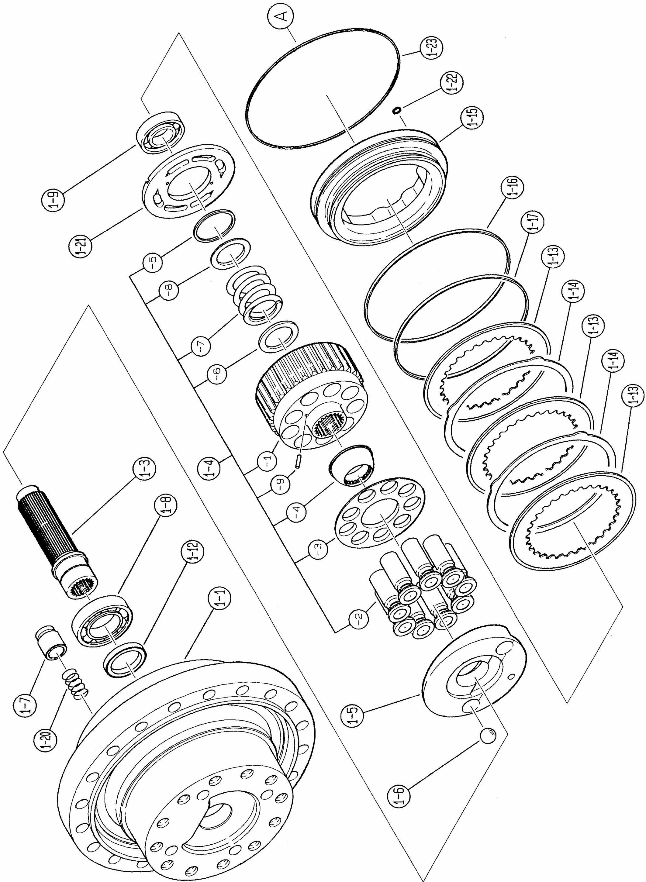
10.)Removing the brake piston (1-15)
Attach a nozzle for compressed air to the oil channel for the parking brake located on the flange (1-1), blow in compressed air into the cylinder chamber for the parking lot to buoy up the brake piston (1-15), and remove it.
After removing the brake piston (1-15), remove the disk plate (1-13) and friction plate (1-14), and then remove the D-rings (1-16, 1-17) from the brake piston (1-15).
Note: When removing the brake piston (1-15), follow the instructions below. a.When blowing in compressed air via the oil channel for the parking brake on the flange (11), ensure that no compressed air leaks. b.When blowing in compressed air via the oil channel for the parking brake on the flange (11), the brake piston (1-15) may come out if the compressed air pressure is excessively high, resulting in injury. To avoid this, set the compressed air pressure at 3 kgf/cm2 or less and proceed with the work while holding down the brake piston (1-15) so that the brake piston (1-15) does not come out.
11.)Removing the cylinder block assembly (14)
Take the cylinder block assembly (1-4) out of the flange (1-1).
Note: When taking out the cylinder block assembly (14), follow the instructions below. a.Hold the cylinder block assembly (1-4) in both hands and slowly take it out while rotating it from side to side. b.Take care not to damage the sliding surface of the cylinder block (1-4-1) against the valve plate (1-21). Damaging it would fail the design performance. c.Take care not to damage the sliding surface of the shoe of the piston assembly (1-4-2).
Damaging it would fail the design performance.
12.)Disassembling the cylinder block assembly (1-4) 12-1.)In order to ensure correct re-assembling in the same relative positions, apply matching marks on the piston assembly (1-4-2) and cylinder block (1-4-1) in imperishable ink, and then remove the piston assembly (1-4-2) and retainer plate (1-4-3) from the cylinder block (1-4-1).
12-2.)In order to ensure correct re-assembling in the same relative positions, apply matching marks on the piston assembly (1-4-2) and retainer plate (1-4-3) in imperishable ink, and then remove the piston assembly (1-4-2) from the retainer plate (1-4-3).
12-3.)Remove the retainer holder (1-4-4) from the cylinder block (1-4-1), and remove the pin (1-4-9 ) from the cylinder block (1-4-1).
12-4.)Secure the cylinder block (1-4-1) in place on the manual press deck with the sliding surface up. Press the collar (1-4-8) with the snap ring (1-4-5) removal jig to make the spring (1-4-7) deflect and remove the snap ring (1-4-5) using a snap ring pliers.
Note: When removing the snap ring (1-4-5), follow the instructions below in order to avoid injuries. a.When removing the snap ring (1-4-5) with snap ring pliers, the snap ring may drop out of the snap ring pliers due to its hardness, leading to injury. When removing the snap ring, always use the disassembling jig and check that the claws of the snap ring pliers are engaged in the snap ring hole before proceeding with the work.
12-5.)Remove the collar (1-4-8), spring (1-4-7) and collar (1-4-6) from the cylinder block (1-4-1).
13.)Removing the swash plate (1-5)
Remove the swash plate (1-5) from the flange (1-1).
Note: When removing the swash plate (1-5), follow the instructions below. a.Take care not to damage the sliding surface of the swash plate (1-5). Damaging it would fail the design performance. b.The swash plate (1-5) may come out with the piston assembly (1-7) and steel ball (1-6). In that case, take precautions to prevent the steel ball (1-6) from falling.
14.)Removing the piston sssembly (1-7) and steel ball (1-6)
Remove the piston assembly (1-7) from the flange (1-1) and remove the spring (1-20).
Remove the steel ball (1-6) from the flange (1-1).
Note: As the steel ball (1-6) is not easy to detach, follow the steps below to remove it. a.As the steel ball (1-6) is mounted on the flange (1-1), degrease the unit with white kerosene, thinner or the like. b.Remove the steel ball (1-6) from the flange (11), using magnet.
15.)Removing the shaft (1-3)
Remove the shaft (1-3) and ball bearing (1-8) from the flange (1-1).
Note: When removing the shaft (1-3), follow the instructions below. a.Take care not to damage the spline section of the shaft (1-3). b.Take care not to damage the oil seal sliding section (1-12) of the shaft (1-3). Damaging will cause oil leakage.
16.)Discharge lubricating oil from the reduction gear
Next, before disassembling the reduction gear section, install eyebolts at two locations opposed to each other by using the shave of the flange (11) and then lift the reduction gear with a crane.
Remove 2 plugs (29) and discharge lubricating oil from the reduction gear.
Note: a.Prepare an oil catcher prior to the operation. b.When lifting with a crane, avoid lifting too high.
Keep it as low as possible (around the knee level) during the operation.
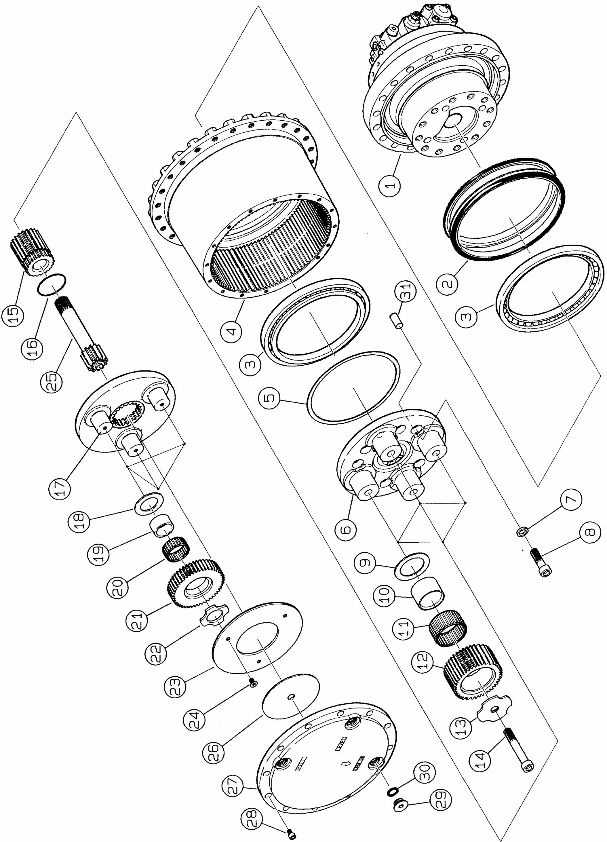
17.)Removing the cover (27)
Loosen the socket head bolt (28) and remove it.
After that, remove the cover (27).
Note: When removing the cover (27), follow the steps below. a.Liquid packing is applied between the cover (27) and housing (4). That is why the cover is not readily removed. Loosen the socket head bolt (28), remove it, and then tap the upper and side surfaces of the cover (27) with a plastic hammer. b.Insert a flathead screwdriver between the cover (27) and housing (4) to remove the cover (27).
18.)Removing the thrust plate (26)
Remove the thrust plate (26) from the upper side of the thrust plate (23).
z
19.)Removing the drive gear (25)
Remove the drive gear (25).
20.)Removing 1st stage holder assembly
Remove the 1st stage holder assembly composed of the holder (17), planetary gear (21), needle bearing (20), inner lace (19), thrust plate (18), thrust plate (22), thrust plate (23) and screw (24).
Note: To remove the 1st stage holder assembly, follow the instructions below. Take care not to have the fingers caught while removing the assembly.
21.)Disassembling 1st stage holder assembly
Fix the 1st stage holder assembly in place with a vise, the heating screw (24) using a dryer, and then loosen the screw.
From holder B (17), remove the screw (24), thrust plate (23), thrust plate (22), planetary gear
B(21), needle bearing (20), inner lace (19), thrust plate (18), in that order.
Note: When loosening the screw (24), follow the instructions below. A screw lock agent is applied on the screw (24). For that reason, it is not loosened readily. An attempt to loosen it may cause damage to the screw, disabling reuse. To loosen it, first heat up the screw adequately using a dryer.
22.)Removing the sun gear B (15)
Remove the sun gear B (15).
23.)Removing the planetary gear C (12)
Fix the flange (1-1) in place, loosen the bolt (14) and then remove it. Remove the thrust plate (13), planetary gear C (12), needle bearing (11), inner lace (10) and thrust plate (9), in that order.
Note: When loosening the bolt (14), follow the instructions below. a.An anti-loosening screw lock agent is applied on the bolt (14). For that reason, ensure that the flange (1-1) is fixed in place. b.When loosening the bolt (14), use a tool with an adequate arm length using an iron pipe, etc.
Forcible operation may result in damage to the back or other injury to the operator.
24.)Disassembling the holder C (6)
Fix the flange (1-1) in place, loosen the bolt (8) and then remove it.
The holder C (6) is fixed in place with the pin (31) on the flange (1-1). Remove the holder C (6) using a press by installing a removal jig from the motor side.
Note: When loosening the bolt (14), follow the instructions below. a.An anti-loosening screw lock agent is applied on the bolt (14). For that reason, ensure that the flange (1-1) is fixed in place. b.When loosening the bolt (14), use a tool with an adequate arm length using an iron pipe, etc.
Forcible operation may result in damage to the back or other injury to the operator.
25.)Separating the flange (1-1) and housing (4)
Mount a jig on the edge of the peripheral flange of the housing (4) and press the flange (1-1) with a press to separate the flange (1-1) from the housing (4).
26.)Removing the floating seal (2)
Push up the periphery of floating seal (2) with a flathead screwdriver and remove the floating seal (2).
27.)Safekeeping of parts
The above completes the disassembly procedure. Wash and clean the disassembled parts and put them in plastic bags, etc. after applying generous amounts of anti-rust oil, and then keep them in a cool, dark and dry place.
High humidity and temperature may cause rust even anti-rust oil has been applied.
Also, store the parts as protected against dust attachment.
5.Maintenance Standards
[1]Maintenance standards for motor components
Table 5 lists maintenance standards for motor components. Follow maintenance standards in Table 5 to check respective components. If the specified tolerance has been exceeded or almost exceeded, replace or repair the part according to the repair and solution procedure.
Table 5. Maintenance Standards for Motor Components
Applicable Part Sections subject to Inspection and Measurement Tolerance Limit Value Repair and Solution Procedure
1-4-2 Piston assembly
1-4-1 Cylinder block
1-4-1 Cylinder block
1-21 Valve plate
1-4-3 Retainer plate 1-4-4 Retainer holder 1.Shoe sliding surface
2.External diameter of the piston
3.External diameter of the piston and bore of the cylinder block (41) 4.Play of the shoe ball Relative roughness 0.8 a or having a surface with a chap or scratch 0.02 mm deep or deeper Relative roughness 1.2 a or having a surface with a chap or scratch 0.02 mm deep or deeper Gap 0.060
Play amount 0.4
1.Sliding surface against the valve plate
Relative roughness 0.8 a or having a surface with a chap or scratch 0.02 mm deep or deeper 2.Bore Relative roughness 1.6 a or having a surface with a chap or scratch 0.02 mm deep or deeper
3.Bore dimension and external diameter of the piston assembly (4-2) 3.Spline in the shaft engagement section. Gap 0.060
In-between distance 38.749 Measurement pin diameter φ3.333 (V1 = 2.80) or the pin is broken. 1.Sliding surface Relative roughness 0.8 a The sliding surface has a scratch of 0.02 mm deep or deeper. Or the surface has a mark from baking. Abnormal level of wear is detected on the sliding surface. 1.Sliding surface Relative roughness 0.8 a The sliding surface has a scratch 0.02 mm deep or deeper. Or the surface has a mark from baking. Lap the shoe sliding surface (#1000). If the scratch cannot be remedied, replace cylinder block assembly 4.
Replace cylinder block assembly 4.
Lap the sliding surface (#1000). If the scratch cannot be remedied, replace cylinder block assembly (4). Replace the cylinder block assembly (4).
Replace cylinder block assembly (4).
Lap the sliding surface (#1000). If the scratch cannot be remedied, replace valve plate (22).
Replace the retainer holder.
Applicable Part Sections subject to Inspection and Measurement Tolerance Limit Value Repair and Solution Procedure
1-5 Swash Place 1.Sliding surface Relative roughness 0.8 a Abnormal level of wear or a scratch 0.02 mm deep or deeper is detected on the sliding surface.
2.Spherical-surface bore for installing the steel ball Relative roughness 1.6 a The spherical surface has a scratch 0.02 mm deep or deeper, or the surface is chapped.
3.Spherical-surface bore for installing the steel ball Ball depth 14.5 Lap the sliding surface (#1000). If the scratch cannot be remedied, replace valve plate (22).
Replace the swash plate.
1-3 shaft 1.External diameter of the oil seal sliding section
1-3 shaft 2.Spline in the cylinder block engagement section.
3.Spline in the drive gear engagement section. Relative roughness 1.6 a In addition to the track of the oil seal sliding track, the ball surface has a scratch 0.02 mm deep or deeper or chapped. Over pin diameter 47.380 Measurement pin diameter φ3.00 or the pin is broken. In-between distance 30.498 Measurement pin diameter φ3.33 or the pin is broken. Replace the shaft.
Replace the shaft.
1-15 Brake piston
1-13 Disk plate 1.External dimensions Height 38.2 Replace the brake piston.
2.Sliding surface Relative roughness 2.5a 3.External dimensions The surface has a scratch 0.02 mm deep or deeper, or the surface is chapped.
1.External dimensions Thickness 3.2 Replace the disk plate.
2.External dimensions The sliding surface has a deep flaw or peeling off of the friction material.
1-8 Ball bearing 1-9 Ball bearing
1-7 piston assembly 1.Rolling surface Flaking or pressing is producing pressure marking. 2.Operation Abnormality is detected with the rotation (abnormal noise, uneven rotation)
1.Shoe sliding surface
Relative roughness 1.6 or having a surface with a chap or scratch 0.02 mm deep or deeper 2.Piston diameter Relative roughness 1.2a or having a surface with a chap or scratch 0.02 mm deep or deeper
3.External diameter of the piston and bore of the flange holder (1-1) 4.Play of the shoe ball Gap 0.040
Play amount 1.0 Replace the ball bearing
Lap the shoe sliding surface (#1000). If the scratch cannot be remedied, using the flange holder kit.
Perform replacement using the flange holder kit.
Applicable Part Sections subject to Inspection and Measurement Tolerance Limit Value Repair and Solution Procedure
1-2-2 Plunger assembly
1-2-1 Base plate
1-2-9 Spool assembly 1.External diameter of the plunger
2.External diameters of the plunger and base plate 1.Hole for mounting the plunger assembly (2-2)
2.Internal diameter of the base plate and external diameter of the plunger 3.Hole for mounting the spool assembly (2-11)
4.Internal diameter of the base plate and external diameter of the spool 5.Free piston sliding section and the seat section of the relief valve assembly 1.External spool diameter
2.External diameter of the spool and internal diameter of the base plate
1-2-7-9 Free piston
1-2-7-1 Housing
1.Sliding and seat sections of the base plate 1.Sliding section against the free piston (external diameter) 1-4-7 spring 1.External dimensions 2.External dimensions
1-18 spring 1.External dimensions 2.External dimensions
1-20 spring 1.External dimensions Relative roughness 0.8 a The surface has a scratch 0.02 mm deep or deeper, or the surface is chapped. Gap 0.060 Replace with a base plate kit
Relative roughness 0.8 a The surface has a scratch 0.02 mm deep or deeper, or the surface is chapped. Gap 0.060 Replace with a base plate kit
Relative roughness 0.8 a The surface has a scratch 0.02 mm deep or deeper, or the surface is chapped. Gap 0.060
The surface has a scratch 0.02 mm deep or deeper, or the surface is chapped.
Relative roughness 0.8 a The surface has a scratch 0.02 mm deep or deeper, or the surface is chapped. Gap 0.060 Replace with a base plate kit
The surface has a scratch 0.02 mm deep or deeper, or the surface is chapped. The surface has a scratch 0.02 mm deep or deeper, or the surface is chapped.
Free length: 61.0
Deformation is observed, and the coil surface is damaged. Free length: 39.0
Deformation is observed, and the coil surface is damaged. Free length: 41.5 Replace with the relief valve assembly.
Applicable Part Sections subject to Inspection and Measurement Tolerance Limit Value Repair and Solution Procedure
2.External dimensions
1-2-4 spring 1.External dimensions Deformation is observed, and the coil surface is damaged. Free length: 48.5
2.Appearance Deformation is observed, and the coil surface is damaged.
1-2-10 spring 1.External dimensions Free length: 28.3
Each O-ring and oil seal 2.Appearance Deformation is observed, and the coil surface is damaged. When disassembling Replace each O-ring and the oil seal.
[2]Maintenance standards for reduction gear
Table 6 lists maintenance standards for reduction gear components. Check the respective parts by following the maintenance standards in Table 6. If any tolerance is exceeded, or almost exceeded, replace or repair the part concerned according to the repair and solution procedure.
Table 6. Maintenance Standards for Reduction Gear Components
Applicable Part Sections subject to Inspection and Measurement Tolerance Limit Value Repair and Solution Procedure
21 Planetary gear
20 Needle
Bearing
19 Inner lace 25 Drive gear
17 Holder
15 Sun gear Tooth thickness 6-piece displacement 66.649 Tooth face Pitching or breakage is detected on at least 10% of the tooth face. Internal diameter Flaking has been observed on thrust face at the internal diameter. Roller rolling surface Flaking has been observed on the surface. Replace the planetary gear.
Replace the planetary gear, needle bearing and inner lace.
Side surface Flaking has been observed on the surface. Tooth thickness 3-piece displacement 29.908 Tooth face Pitching or breakage is detected on at least 10% of the tooth face. Spline section Over pin diameter 38.989 Measurement pin diameter φ3.00 or the pin is broken. Inner tooth thickness In-between distance 66.742 Measurement pin diameter φ7.00 or the pin is broken. Tooth thickness 4-piece displacement 41.371 Tooth face Pitching or breakage is detected on at least 10% of the tooth face. Replace the drive gear
Replace the drive gear and at the same time check the shaft.
Replace the holder.
Replace the sun gear
Applicable Part Sections subject to Inspection and Measurement Tolerance Limit Value Repair and Solution Procedure
12 Planetary gear
11 Needle
Bearing
10 Inner lace Tooth thickness 6-piece displacement 65.662 Tooth face Pitching or breakage is detected on at least 10% of the tooth face. Internal diameter Flaking has been observed on thrust face at the internal diameter. Roller rolling surface Flaking has been observed on the surface.
Side surface Flaking has been observed on the surface. Replace the planetary gear.
Replace the planetary gear, needle bearing and inner lace.
4 Housing Tooth thickness In-between distance 330.449 Measurement pin diameter φ7.000 Tooth face Pitching or breakage is detected on at least 10% of the tooth face. Replace the housing.
5 Shim 1-1 flange
26 Thrust
Plate
3 Angular
Bearing When disassembling Replace the shim.
2nd-speed piston bore and the external diameter of the piston assembly Gap 0.040 Perform replacement using the flange kit.
2nd-speed piston bore Relative roughness 1.2 a or having a surface with a chap or scratch 0.02 mm deep or deeper Thickness Plate thickness: 3.3, plate thickness: 2.5 Plate thickness: 2.9, plate thickness: 2.0 Plate thickness 2.7 or the sliding surface is severely damaged. Ball rolling surface Flaking is observed on the surface. Replace the thrust plate.
Replace the angular bearing.
Operation Running causes abnormal noises and awkward rotation.
2 Floating seal Sliding surface Serious damage has done, including deep scars that may cause oil leakage. O-ring Cracks are observed on the surface.
Replace the floating seal. Besides the above, perform replacement in disassembling situations; during the disassembly period, oil leakage may occur during re-assembling process because the landing tracks do not match. Each O-ring When disassembling, replace each O-ring.
6.Assembly of the Motor
[1]Precautions for the assembly of the motor
Read the following precautions carefully prior to start assembling the motor.
1. When starting the assembly operation, be sure to wear safety shoes and other protective gear. 2. When assembling the motor, use the specified tools. 3. In order to prevent injuries during the disassembly work, prepare a stable workbench that is about waist height, and perform the disassembly on the workbench. 4. The motor is comprised of precision components. As such, any attachment of foreign matter must be avoided. Assemble the motor in a dust-free room to prevent the components from becoming contaminated with soil or dust. 5. The motor is comprised of precision components. Any denting or damaging of its surface must be avoided.
While handling motor components in the assembly process, be fully attentive not to dent or damage them. 6. Be sure to repair all damage detected in the disassembly process. Prepare all replacement parts needed beforehand, and then start assembling. 7. Remove metal chips and foreign matter from all parts and check that all parts are free from burrs and indentations before starting the assembling procedure. When detecting burrs or indentations, provide remedies by using a whetstone. 8. In the assembling procedure, apply clean hydraulic oil on respective sliding sections and rolling sections prior to the assembly work. 9. Fully degrease sections where a screw lock agent and liquid packing are applied and remove water prior to the assembly work. 10.Replace O-rings, backup rings and other sealing parts with new ones. 11.In the assembling procedure, take care not to allow O-rings and backup rings to be damaged. When assembling O-rings and backup rings, apply a small amount of grease before assembling. 12.When assembling, it is helpful to use vaseline, grease, etc., to prevent fall of parts involved. 13.Tighten bolts up to the torque specifications shown in Table 4 in Chapter 5, section 2 in the respective joins. Control tightening torque using a torque wrench. 14.After completing the assembly, stop all ports in order to block dust intrusion into the inside of the motor.
[2]Assembling procedure
Follow the procedure below to assemble the motor, observing the precautions given in section 1.
1.)Assembly of reduction gear section 1.)Assembling the floating seal (2) onto the flange (1-1)
Check the following points for the floating seal (2), and then assemble the floating seal (2) onto the flange (1-1), using a floating seal assembly jig.
Confirmation: a.Check that the mounting surface of the floating seal (2) on the flange (1-1) is free from soil or dust. b.Fully degrease the mounting surface of the floating seal (2) on the flange (1-1). c.Check that the surface of the O-ring of the floating seal (2) is free from soil or dust. d.Fully degrease the surface of the O-ring of the floating seal (2).
2.)Assembly of the angular bearing (3) onto the housing (4)
Press fit the angular bearing (3) onto the housing (4), using a press-fit jig and a press.
3.)Assembly of the angular bearing (2) onto the housing (4)
Check the following points for the floating seal (2), and then assemble the floating seal (2) onto the housing (4), using a floating seal assembly jig.
Confirmation: a.Check that the mounting surface of the floating seal (2) on the housing (4) is free from soil or dust. b.Fully degrease the mounting surface of the floating seal (2) on the housing (4). c.Check that the surface of the O-ring of the floating seal (2) is free from soil or dust. d.Fully degrease the surface of the O-ring of the floating seal (2).
4.)Assembling the housing (4) onto the the flange (1-1)
Check the following points. Then assemble the housing (4) onto the flange (1-1) so that the floating seal (2) on the flange (1-1) falls on the floating seal (2) on the housing (4).
Confirmation: a.Check that the sliding surface of the seal ring of the floating seal (2) is free from soil or dust. b.Apply lubricating oil for the reduction gear or hydraulic oil all around the sliding surface of the seal ring of the floating seal (1-2). c.When assembling the flange holder (1-1) on the housing (1-6), check that the shaft centers are aligned, and then proceed with the assembly.
5.)Selecting the thickness of the shim (5)
According to the following procedure, select the shim thickness for pre-pressure adjustment. 5-1.) Using a shim thickness adjusting jig, apply load of 3000 kgf on the end surface of the inner race of the angular bearing (3). 5-2.) In this step, measure step dimension H between the inner race surface in the angular bearing (3) and the end surface of the flange (1-1). 5-3.) Measure step dimension “h” for the holder (6). 5-4.) Select the shim (5) and form a combination so that the shim thickness is appropriate for (H - h).
Note: a.Do not use the shim (5) that has been used once already. b.Perform this procedure securely. Failure of prepressure adjustment leads to breakage of the reduction gear during operation. c.Clean the surface subject to measurement and start measurement.
*1 Press load 300 kgf *2 Dimension H *3 Dimension h
*1
*2 *3
6.)Assembling the holder (6)
Fix the flange (1-1) in place, and erect pins (31) (four locations) on the flange (1-1).
Using grease, bring the shim selected under step 5.) to adhere to the holder (6), adjust so that pin hole rests on it with pin holes aligned, and then press fit the shim onto the holder.
Mount the washer (7) onto the holder (8), and tighten the bolt (8) with locktite applied around its neck at the specified torque.)
Note: a.Check that the pin (31) is not down. b.The washer (7) is provided with a spike for resisting loosening. Install the washer with the spike on the washer side. c.Wash the thread section of the bolt (8) degrease it and apply locktite on the bolt. d.Clean the bore for the screw on the flange (1-1) and fully degrease it.
* Pay attention to the assembling direction for washer 7.
Assemble toward the direction shown in the figure on the right.
7.)Assembling the planetary gear (12)
Assemble the thrust plate (9) onto the planetary gear (12).
Next, assemble the needle bearing (11) onto the planetary gear (12).
Lastly, after assembling the inner race (10), engage the bore section of the inner race (10) with the trunnion sections (at four locations) on the flange (1-1), and then assemble the planetary gear (12).
Note: a.When assembling the thrust plate (9) onto the planetary gear (12), assemble so that the blanking mark on the thrust plate (9) left by the press comes on the flange (1-1) side. b.In the last step for assembling the planetary gear (12) onto the flange (1-1), assemble so that the inner teeth of the housing (4) are engaged with those of the planetary gear (12). c.Take care for the assembling direction for the planetary gear (12).
*1
*2
*1 Direct the blanking mark side to face holder C (6). *2 Assembling direction for thrust plate (9)
8.)Assembling the thrust plate (13)
Install the thrust plate (13) onto planetary gear (12) so that the chamfer at the bolt bore section comes under the neck section of the bolt (14).
After the installation, install the bolt (14) with locktite applied on the thread section, and then tighten it at the specified torque.
Note: a.Check that the assembling direction for the thrust plate (13) is correct. Otherwise, the neck section of the bolt is damaged, and the bolt will be broken. b.Wash the thread section of the bolt (14), degrease it and apply locktite on the bolt. c.Clean the bore for the screw on the flange (1-1) and degrease it well.
*1
9.)Assembling the sun gear (15)
After checking that the sun gear (15) has the snap ring (16) installed, install the sun gear (15) in the center of 4 planetary gears (12).
Note: Assemble by engaging the teeth of the planetary gears (12) and those of the sun gear B (15).
*1 Install so that the chamfer (C2) side comes on the socket head bolt (14) side.
10.)Assembling the holder (17)
Engage the inner teeth of the holder (17) with those of the sun gear (15), and then assemble the holder (17) onto the sun gear (15).
11.)Assembling the planetary gear (21)
Assemble the thrust plate (18) onto the planetary gear (21).
Next, assemble the needle bearing (20) onto planetary gear (21).
Lastly, after assembling the inner race (19), engage the bore section of the inner race (19) with the trunnion sections (at 3 locations) on the holder (17), and then assemble the planetary gear (21) onto the holder (17).
Note: a.When assembling the thrust plate (18) onto the planetary gear (21), assemble so that the blanking mark on the thrust plate (18) left by the press comes on the side of the holder (17). b.In the last step for assembling planetary gear (21) onto the holder (17), assemble so that the inner teeth of the housing (4) are engaged with those of the planetary gear (21). c.Take care for the assembling direction for the planetary gear (21).
*1
*2
*1 Direct the blanking mark side to face holder B (17). *2 Assembling direction for thrust plate (18)
12.)Assembling the planetary gear (25)
Assemble the thrust plate (22) onto the planetary gear (21), and then assemble the thrust plate (23). Assemble the screw (24) with locktite applied on its thread section, and tighten to the specified torque.
Direct the spline side of the drive gear (25) to face the motor assembly. Assemble it in the center of 3 planetary gears (21) and engage the teeth of the planetary gear (21) with those of the drive gear (125).
Note: a.Take care for the assembling direction for the planetary gear (22). b.Wash and clean the bore of the holder (17) and the thread section of the screw (24), and degrease them well.
*1
*2
*1 Direct the blanking mark side to face the planetary gear C (12). *2 Assembling direction for the thrust plate (13)
13.)Assembling the thrust plate (26)
Measure the step between the end surface of the housing (4) and that of the thrust plate (23) using a thrust plate selecting jig, and select the thrust plate (26) according to the table below to assemble it.
Note: Assemble the thrust plate (26) by aligning the central hole in the thrust plate with the convex section of the drive gear (25).
Step Dimension Applicable Thrust Plate 1.20 to 0.67 20941-62306 0.66 to 0.04 20941-62307 0.03 to -0.16 20941-62308 -0.17 to -0.41 20941-62309 -0.42 to -0.80 B0841-23017
*1 Measuring the step
*1
14.)Assembling the holder (27)
Completely remove foreign matter on the alignment surface of the housing (4) and cover (27).
Next, degrease the alignment surface of the housing (4) and cover (27) well.
Next, apply liquid packing at the corner of the spigot joint portion of the cover (27) and housing (4) alignment surface. Then align the screw bore of the housing (4) with the bolt bore to install the cover (27) onto the housing (4).
Lastly, install the socket head bolt (28) and tighten the socket head bolt (28) at the specified torque.
15.)Assembling the plug (29)
Remove the O-ring (30) attached to the plug (29).
Replacing it, assemble a new O-ring onto the plug (29).
Next, assemble the plug (29) onto each of the oil fill, discharge and level ports (3 ports) of the cover (27) and tighten them at the specified torque.
That completes the assembly of the reduction gear section. The next section describes the assembly of the motor section. Refer to "(2) Assembly of Motor" to proceed with the assembling procedure.
2.)Assembly of motor 1.)Assembling the oil seal (1-12)
Check that the oil seal (1-12) is not installed onto the flange (1-1). If not, press fit the oil seal (1-12) onto the flange (1-1), using an oil seal press-fit jig.
Note: a.Prior to press-fit operation, apply grease on the bore section of the oil seal (1-12) press-fit section of the flange (1-1) and bore surface of the oil seal (1-12). b.Press fit after applying grease on the lip section of the bore of the oil seal (1-12). c.When press fitting, use a press at rights.
Inclined press-fitting force damages the side surface of the oil seal (1-12). d.When press fitting, take care not to damage the lip section of the bore of the oil seal (1-12).
Damaging it may cause oil leakage, which could result in breakage of the interior of the reduction gear while the motor is operating.
2.)Assembling the piston assembly (1-7)
Assemble the spring (1-20) into the hole on the flange (1-1) provided for assembling the piston assembly (1-7).
Next, assemble the piston assembly (1-7) onto the flange (1-1).
Note: a.When assembling the spring (1-20), check that the spring is placed in the center of the hole. b.When assembling the piston assembly (1-7), do so with the cylindrical section down. c.Prior to assembling the piston assembly (1-7), apply hydraulic oil on the surface of the bore provided on the flange (1-1) for piston installation and the side surface of the cylindrical section of the piston assembly (1-7). d.After assembling the piston assembly (1-7), check that the piston assembly (1-7) operates smoothly.
3.)Assembling the steel ball (1-6)
Assemble the steel ball (1-6) into the sphericalsurface bore on the flange (1-1).
Note: Prior to assembling the steel ball (1-6), apply hydraulic oil on the surface of the sphericalsurface bore provided on the flange (1-1) and the steel ball (1-6).
4.)Assembling the shaft (1-3)
Press fit the ball bearing (1-8) onto the shaft (13), using a bearing press-fit jig.
Next, assemble the shaft (1-3) in the center of the flange (1-1).
Note: a.When assembling the ball bearing (1-8), check that it is installed at rights. b.After assembling the shaft (1-3), check that the shaft rotates smoothly.
5.)Assembling the swash plate (1-5)
With the graded side up, assemble the swash plate (1-5) onto the flange (1-1).
Note: a.Assemble so that the rear spherical -surface bore on the swash plate (1-5) is aligned with the steel ball (1-6). b.After applying hydraulic oil on the steel ball (16), assemble the swash plate (1-5). c.After assembling the swash plate (1-5), check that the swash plate operates smoothly.
6.)Assembling the cylinder block assembly (1-4) 6-1.) Place the cylinder block (1-4-1) on the work bench of a manual press with its surface sliding against the valve plate (121) up. With the graded side of the collar (1-4-6) down, assemble it into the cylinder block (1-4-1), and place the spring (1-4-7) and the collar (1-4-8), in that order, on the collar (1-4-6).
6-2.) Using a jig, press in the upper surface of the collar (1-4-8) and assemble the snap ring (1-4-5).
Note: a.When assembling the snap ring (1-4-5) with snap ring pliers, the snap ring may drop out of the snap ring pliers due to its hardness, leading to injury. When assembling the snap ring, always use a jig and check that the claws of the snap ring pliers are engaged in the snap ring hole before proceeding with the work. b.When it is difficult to contract the snap ring, use snap ring pliers that are onesize larger than required. c.When pressing in the collar (1-4-8), be sure to align the center of the cylinder block with that of the press.
6-3.) Place the cylinder block (1-4-1) on the work bench with its surface sliding against the valve plate (1-21) down.
Assemble 3 pins (1-4-9) into the inclined holes of the cylinder block.
Note: a.When placing the cylinder block (1-4-1) on the work bench, check that no foreign matter is present on it. b.Take care not to damage the sliding surface of the cylinder block (1-4-1) that slides against the valve plate (1-21).
Damaging the sliding surface may affect the motor performance, which may lead to early failure of the motor. c.When assembling the pin (1-4-9), assemble it after applying grease in the pin halls.
6-4.) Assemble the retainer holder (1-4-4) onto the cylinder block (1-4-1).
6-5.) With the surface having tapered surface on the side down, assembly 9 piston assembly (1-4-2) onto the retainer plate (1-4-3).
6-6.) Assembly the piston assembly (1-4-2) onto the cylinder block (1-4-1).
Note: a.After applying hydraulic oil in the halls (at 9 locations) for assembling the cylinder block (1-4-1), assemble the piston assembly (1-4-2). b.Apply hydraulic oil on the spherical surface of the retainer holder (1-4-4), and then proceed with the assembling procedure.
7.)Assembling the cylinder block assembly (1-4)
With the sliding surface of the valve plate (1-21) of the cylinder block assembly (1-4) up, assemble the cylinder block assembly (1-4) into the flange (1-1) while engaging the inner teeth spline of the cylinder block (1-4-1) with the external teeth splines of the retainer holder (1-44) and shaft (1-3).
Note: a.When assembling, take care not to allow the piston assembly (1-4-2), retainer plate (1-4-3), retainer holder (1-4-4), etc. to drop out of the cylinder block assembly (1-4). b.Prior to the assembling procedure, apply hydraulic oil on the surface of the swash plate (1-5) and the sliding surface of the piston assembly (1-4-2).
8.)Assembling the disk plate (1-13)
While engaging the inner teeth of the disk plate (1-13) with the external teeth of the cylinder block (1-4-1), assemble the disk plate onto the flange (1-1).
Also, assemble it onto the flange (1-1) so that the peripheral arc section of the friction plate (1-14) is aligned with the notch section of the flange (11).
According to the procedures above, assemble the disk plate (1-13) and the friction plate (1-14), in that order.
Note: The disk plate (1-13) is a wet-type disk. Prior to the assembling procedure, soak the portion of friction material in hydraulic oil to let it absorb hydraulic oil adequately.
9.)Assembling the brake piston (1-15)
Assemble the D-rings (1-16, 1-17) onto the brake piston (1-15).
With the side with the larger diameter of the brake piston (1-15) up, assemble it onto the flange (1-1).
Note: a.When installing the D-rings (1-16, 1-17), generously apply grease on the rings. b.Using a positioning jig, align the knock pin holes of the base plate (1-2-1) on the flange (11) and the brake piston (1-15) so that they are arranged in line, and then assemble the brake piston (1-15). c.When assembling the brake piston (1-15), apply grease on the external surface and inside the bore of the flange (1-1). d.Assemble while evenly pressing down the brake piston (1-15) so that it may not incline.
Assembling the piston as inclined may cause operational failure or ripping of a D-ring.
10.)Assembling the spring (1-18)
Assemble the springs (1-18) into the bores (at eight locations) provided for assembling the springs (1-18) on the brake piston (1-15).
11.)Assembling the valve plate (1-21)
Place the base plate (1-2-1) on a work bench and press fit the bearing (1-9) in the center of the base plate (1-2-1), using a bearing press-fit jig.
After checking that the knock pin (1-19) is installed on the base plate (1-2-1), assemble the valve plate (1-21) onto the base plate (1-2-1).
Note: a.Assemble the valve plate (1-21) with its copper-base alloy side up. b.In order to prevent falling of the valve plate (121), apply grease sufficiently on the alignment surface of the base plate (1-2-1) and the valve plate (1-21). c.Take care not to damage the copper-base alloy surface of the valve plate (1-21).
12.)Assembling the base plate (1-2-1)
Assemble the O-rings (1-23) and O-rings (1-22) (at four locations) onto the upper surface of the flange (1-1).
Assemble the knock pin (1-19) on the base plate (1-2-1).
With the surface of the base plate (1-21) contacting the valve plate (1-21) when assembled down, assemble the base plate onto the flange (1-1) and tighten it using the socket head bolt (1-11).
Note: a.Apply grease on the O-ring (1-23). b.Do not apply grease on the O-ring (1-22). c.Assemble the knock pin (1-19) with its tapered section up. d.After applying hydraulic oil on the surface of the valve plate (1-21) and the surface of the cylinder block (1-4-1), assemble the base plate (1-2-1). e.When assembling the base plate (1-2-1), check that the valve plate will not fall even though the side having the valve plate (1-21) installed is oriented downward. f.Check the location where the O-ring (1-22) is assembled and the location of the notch for the oil channel on the base plate (1-2-1). g.Check for the locations of the knock pin (1-19) mounted on the base plate (1-2-1), the hole on the base plate (1-2-1) for installing the spring (1-18), and the knock pin hole on the flange (11) side as well as the location of the spring (118). h.When tightening the socket head bolt (1-11), tighten it by applying force evenly along the periphery.
13.)Assembling the valve assembly (1-2-9)
Assemble the spring (1-2-10) into the valve assembly (1-2-9), and then onto the base plate (1-2-1). After assembling the valve assembly (12-9), check that the O-ring (1-2-12) is installed onto the plug (1-2-11). Then, assemble the plug (1-2-11) onto the base plate (1-2-1) and tighten to the specified torque.
Next, check that the O-ring (1-2-12) is installed onto the plug (1-2-14), and assemble the washer (1-2-15) into the spring guide (1-2-13), assemble the plug (1-2-14) onto the base plate (1-2-1), and then tighten to the specified torque.
Note: a.With the piping port side of the base plate (1-21) on the near side, assemble the valve assembly (1-2-9) onto the base plate (1-2-1) so that the side of the valve assembly (1-2-9) with the spring (1-2-10) installed comes on the righthand side. Reverse assembly leads to trouble such as switching failure. b.Apply hydraulic oil around the exterior of the valve assembly (1-2-9) and then proceed with the assembling procedure. c.After assembling the valve assembly (1-2-9), check that the valve assembly (1-2-9) operates smoothly.
14.)Assembling the relief valve assembly (1-27)
Check that the poppet seat (1-2-7-3) is installed on the tip of the relief valve assembly (1-2-7), assemble the relief valve assembly (1-2-7) onto the base plate (1-2-1), and then tighten to the specified torque.
Note: a.Replace the O-ring (1-2-7-7) with a new one before assembling the valve assembly. b.Check that the O-ring (1-2-7-17) and the backup ring (1-2-7-18) are installed onto the poppet seat (1-2-7-3). c.Apply grease on the O-ring (1-2-7-17) and the backup ring (1-2-7-18), and then assemble them.
15.)Assembling the plunger assembly (1-2-2)
Assemble the plunger assembly (1-2-2) onto the base plate (1-2-1).
Note: a.Slowly assemble the plunger assembly (1-2-2) while rotating it. b.Assemble the plunger assembly (1-2-2) at rights. c.When the plunger assembly (1-2-2) is stuck, do not attempt to move it forcibly. Instead, softly tap it with a plastic hammer, etc. d.Apply hydraulic oil around the exterior of the plunger assembly (1-2-2) and then proceed with the assembling procedure.
16.)Assembling the cap assembly (1-2-6)
Assemble the spring seat (1-2-3) and the spring (1-2-4), in that order, into the plunger assembly (1-2-2).
Assemble the check valve (1-2-22) and the spring (1-2-23), in that order, into the hole next to the hole for assembling the cap assembly (1-2-6) on the base plate (1-2-1).
Check that the O-ring (1-2-6-2) is installed in the cap assembly (1-2-6) and that the O-ring (1-2-24) is installed onto the base plate (1-2-1), install the spring seat (1-2-5) into the cap assembly (1-2-6).
Then assemble the cap assembly (1-2-6) onto the base plate (1-2-1).
Lastly, tighten the socket head bolt (1-2-6-3) at the specified torque.
Note: a.Apply grease on the O-ring (1-2-6-2). b.The spring (1-2-4) is pushing up the cap assembly (1-2-6). When tightening the socket head bolt (1-2-6-3), hold down the cap assembly (1-2-6) by hand while tightening it. c.When tightening the socket head bolt (1-2-6-3), proceed little by little while tightening at the four locations evenly. If the cap assembly (1-2-6) is tightened as inclined, the O-ring (1-2-6-2) may be damaged, leading to oil leakage.
That completes the assembling procedure for this motor. After completing the assembling procedure, follow Chapter 10 "Storing the Motor" of the operator's manual should the motor be stored. Also, should the motor be mounted on the machine, follow Chapter 11 "Motor Installation," Chapter 12 "Confirmation," and Chapter 13 "Production Run" and the operator's manual for the machine well.
7.Hydraulic Oil
Hydraulic oil is essential for transmission of the drive force and lubrication of the hydraulic equipment parts. Improper selection or handling of the hydraulic oil may cause a problem, such as "expected performance of the hydraulic equipment cannot be achieved" or "the hydraulic equipment life is extremely shortened." Therefore, it is important to fully understand the following before selecting and handling the hydraulic oil. [1]Required properties for the hydraulic oil
Hydraulic oil is used for drive force transmission and hydraulic equipment lubrication. In addition, it has a life.
From these points, the following properties are required for the hydraulic oil:
(1)Drive force transmission (a) A viscosity appropriate for the hydraulic equipment and low viscosity change with temperature. (b) Good antifoam properties. (c) High ignition point. (d) Compatible with the packing and seal material. (2)Hydraulic equipment lubrication (a) Good lubrication even when operational conditions, such as temperature and pressure, vary. (b) Good antirust properties. (c) Good water and contaminant separation. (3)Hydraulic oil life (a) Chemically stable. (b) Good oxidation stability and less deterioration after long use. (4)Others (a) Transparent color.
Select hydraulic oil that meets the requirements above.
[2]Types of hydraulic oil and selecting appropriate one
There are various types of hydraulic oil. They can be systematically categorized as follows:
(1)Mineral-based hydraulic oil
This oil is generally used and can be easily obtained. Thus, most hydraulic equipment uses this type of hydraulic oil.
(2)Synthetic hydraulic oil
This oil been developed for aircraft-related uses that have special requirements, and has excellent temperature characteristics and low temperature fluidity. However, this type of hydraulic oil is expensive.
Phosphoric acid ester-based hydraulic oil, which is used as flame-resistant hydraulic oil, also belongs to this category.
(3)Aqueous hydraulic oil
This oil is used as flame-resistant hydraulic oil for those pieces of hydraulic equipment that are in extreme danger of fire that can be caused by oil leaking or other factors. Die casting machines, mills, and heating furnaces, for example, use this type of oil.
(4)Biodegradable hydraulic oil
This oil has been developed for the purpose of environmental conservation. This type of oil is decomposed by bacteria so that soil and rivers will not be contaminated by oil leaks.
Table 5 shows the compatibility of each type of oil with the motor. Select hydraulic oil by following this table.
Table 5. Compatibility of Hydraulic Oil with the Motor
: This type of oil has no problem to be used. : Please contact us if this type of oil needs to be used. × : Do not use these types of oil as they can cause a problem.
The viscosity of hydraulic oil varies depending on the operating temperature. Since the viscosity of hydraulic oil significantly affects lubrication and drive force transmission of the motor, changing to hydraulic oil appropriate for the operating temperature is necessary.
Check the operating temperature of the mother machine and the management temperature of the hydraulic oil in the hydraulic equipment, and then select hydraulic oil to use based on Table 6.
Hydraulic Oil Compatibility with the Motor Mineral-based hydraulic oil
Synthetic hydraulic oil ×
Aqueous hydraulic oil × Biodegradable hydraulic oil
Table 6. Operating Temperature and Appropriate Hydraulic oil
[4]Managing the temperature of the hydraulic oil 1. Temperature of the hydraulic oil in operation
Hydraulic equipment is very sensitive to the viscosity of the hydraulic oil. In particular, when the temperature of the hydraulic oil becomes too high in the operating hydraulic equipment, deterioration of the oil will be accelerated and the extremely reduced viscosity of the oil will cause a malfunction or breakdown of the equipment. Table 7 shows the applicable viscosity range of the hydraulic oil used in the hydraulic equipment.
Table 7. Applicable Viscosity Range of the Hydraulic Oil
For continuous operation, use a cooler or other equipment to keep the temperature of the hydraulic oils between -10 to +80°C and within the viscosity range shown in Table 7.
2. Temperature of the hydraulic oil at low temperature To start the motor at low temperature when the temperature of the hydraulic oil is below the allowable range shown in Table 7, raise the temperature of the hydraulic oil using a warm-up operation or a heater and slowly start the motor. When the temperature of the hydraulic oil is too low, the hydraulic pump suction may be weakened due to too high viscosity or oil may not circulate due to excessive resistance.
Operating Environment Cold Area Warm Area Hot Area Environmental temperature -10 to +25°C 0 to +35°C
Appropriate hydraulic oil ISO VG32 or equivalent ISO VG46 or equivalent ISO VG56 or equivalent
Note If the machine is used in an wide range of environmental temperatures from low to high, consult with your hydraulic oil manufacturer and use abrasion-resistant hydraulic oil with high viscosity (140 or higher) that can be used for all seasons.
Do not mix different types of hydraulic oil. To change to different hydraulic oil, flush the hydraulic circuit thoroughly before replacing.
Important
Viscosity Oil Temperature ISO VG32 ISO VG46 Appropriate range 25 to 100 cSt +17 to +45°C +23 to +55°C Allowable range 15 to 500 cSt -7 to +60°C 0 to +70°C
Important When the viscosity of the oil is too low, the sliding section of the piston motor can be scorched or worn earlier and become unable to operate. Therefore, select hydraulic oil appropriate for the environmental temperature and the operating temperature.
WAt low temperatures, do not rapidly start the operation after you have raised the temperature of the hydraulic oil. The rapid flow of warm hydraulic oil into the cold equipment rises the temperature of the equipment. This may cause the valves to malfunction because of the difference in thermal expansion between the parts. Therefore, start the operation slowly to gradually raise the temperature of the equipment.
Important
The gap between the parts such as the piston motor and the double counter balance valve is very small, thus very sensitive to contamination in the hydraulic oil. Dirty hydraulic oil can cause a problem such as malfunction of valves and performance degradation. To prevent this problem, keep the degree of contamination in hydraulic oil within the level of NAS rank 9.
To manage the contamination in the hydraulic oil, set a filter in the hydraulic circuit. (See Chapter 5.) A dirty filter may reduce the filtering performance of the hydraulic oil, or worse, contaminate the oil. Therefore, use a filter with an indicator that allows checking the filter clog from outside and a built-in relief valve that can bypass the flow according to clog state.
To properly manage the degree of contamination in the hydraulic oil, the filter must also be managed. Regularly conduct maintenance checks for the filter.
Note
Important
8.Reduction Gear Lubricating Oil
Reduction gear lubricating oil is essential for drive force transmission and lubrication of reduction gear parts. Improper selection or handling of reduction gear lubricating oil may cause a problem, such as "expected performance of the reduction gear cannot be achieved" or "the reduction gear life is extremely shortened." Therefore, it is important to fully understand the following before selecting and handling reduction gear lubricating oil. [1]Functions of and requirements for reduction gear lubricating oil
Reduction gear lubricating oil has the following functions: (1)Forming oil film between metals to provide reduced friction and smooth lubrication between them so that the driving force will not be lost. (2)Forming oil film between metals to provide smooth lubrication between them so that the gear will not be damaged by wear or scorching (3)Providing smooth lubrication between metals to prevent temperature rise caused by frictional heat. (4)Preventing rust and corrosion caused by entry of water or other reasons.
To fulfill all these functions, the following properties are required for the reduction gear lubricating oil. (1)High oil film strength. (good extreme-pressure properties.) (2)Appropriate viscosity and high viscosity index. (3)Good oxidation stability. (4)Good antifoam properties. (5)Good antirust properties. (6)Good low-temperature fluidity. (7)Good water separation. (8)Less corrosive. (9)Does not affect on the seal material.
Select reduction gear lubricating oil that meets the requirements above.
[2]Types of reduction gear lubricating oil and selecting appropriate one
Table 8 shows the API Service Categories for reduction gear lubricating oil.
Table 8. API Service Categories for Reduction Gear Lubricating Oil
Use reduction gear lubricating oil equivalent to "GL-4 or GL-5".
Service Categories Type of Service Applications
GL-1 Spiral bevels or worm gears with small surface pressure and sliding velocity Used for manual transmission on rare occasions and rarely used today.
GL-2 Slightly more demanding worm gears than above mentioned. Used for industrial worm reducers.
GL-3 Slightly more demanding spiral bevels and manual transmission Mainly used for manual transmission.
GL-4
GL-5 Hypoid gears under highspeed and low-load or low-speed and high-load
Much more demanding hypoid gear to which shock load is applied Hypoid gear reducer under normal conditions. Also used for manual transmission. Passenger cars, racing cars, and the track rear axle of the hypoid unit that have high requisite.
Table 9 shows JIS viscosity grades for reduction gear lubricating oil.
Table 9. JIS viscosity Grades for Reduction Gear Lubricating Oil
Higher viscosity provides more load bearing but may cause a problem with the starting performance if the viscosity is too high. Therefore, selecting reduction gear lubricating oil appropriate for the operating temperature is necessary.
Type (Viscosity grade)
Kinematic Viscosity cSt (100°C) SAE 75W 4.1 or higher SAE 80W 7.0 or higher SAE 85W 11.0 or higher SAE 90 13.5 or higher and less than 24.0 SAE 140 24.0 or higher and less than 41.0
Table 10 shows selection criteria for the viscosity of the reduction gear lubricating oil for various operating temperatures. Select the viscosity of the reduction gear lubricating oil by following this table. Note that a given amount of diamond hypoid gear oil 90 from Mitsubishi Oil has been fed by the factory setting.
Table 10. Selection Criteria for the Viscosity of the Reduction Gear Lubricating Oil for Various Operating Temperatures
Operating
Temperature Extremely Hot Area Summer Spring, Fall, Winter Extremely Cold Area
Viscosity grade SAE140 SAE90 or SAE140 SAE90 SAE80W
Important Do not mix different types of reduction gear lubricating oil when replacing the lubricating oil.
9.Storing the Motor
[1]Immediately after purchase
The guaranteed storage period of the swash plate-type piston motor with case rotation type reduction gear for the open circuit is one year after shipment form the factory.Do not store the motor for longer than this period. In addition, do not disassemble the motor during the storage period or loosen the bolts.
How to store the motor
Some hydraulic oil is applied on the inside of the equipment because it is tested before the shipment. In addition, antirust agent is applied on each port section, the installation face of the mother machine, and the mounting tap section. Do not wipe off the antirust agent. Storage period should be within three months. If longer storage is expected, please contact us in advance because the way to prevent rust is different.
For shipment, the product is covered with a plastic bag that prevents dust from entering. Do not remove the plastic bag when storing the product.
Store the product in an indoor area to protect it from rainwater etc. Avoid a place subject to high temperature and humidity. Store the product at ordinary temperature and humidity.
The product is shipped with the dedicated palette. Leave the packaging as it is not to damage the motor and store it in a stable place.
[2]Management method after maintenance check
When storing the motor after a maintenance check, follow the instructions below.
In this case, please be reminded that you are responsible for any problem (for example, scratches and rust) that occurs on the motor.
How to store the motor
When storing the motor after a maintenance check, make sure that fastening bolts of all sections are fastened to a given tightening torque and that air is not leaking from any sealed section, and then start and stop the motor before storing. (For the procedure to run the motor, see the operating method described elsewhere. ) If it is impossible to run the motor, feed about 500 cc of hydraulic oil into the piston motor case and about 3.5 L of reduction gear lubricating oil into the reduction gear before storing.
Before storing, spray vaporizing antirust oil on the insides of the piston motor case, the piston motor circuit, and the reduction gear from the ports of the motor and then seal all the port sections with plugs by following the instructions below.
Apply antirust agent on the non-coated areas on the installation faces, screw sections, and port sections, etc.
To prevent dust from entering, cover the product with a plastic bag and then store it. Store the product in a stable place, placing the reduction gear side down. Store the product in an indoor area to protect it from rainwater etc. Avoid a place subject to high temperature and humidity. Store the product at ordinary temperature and humidity.
Instructions for preventing rust 1. Preventing rust on the non-coated exterior areas
To prevent rust on the non-coated exterior areas, apply antirust agent on them following the instructions below. (1)Areas that need antirust treatment The installation surface to the mother machine, the threaded section for connection, and the noncoated areas of the pipe port section or other sections (2)Applying method Apply agent once with a brush. (3)Recommended antirust agent Brand:NOX-RUST 366-30 Manufacturer: Parker Industries, Inc. 2. Preventing rust on the interior areas of the piston motor and the reduction gear
To prevent rust on the interior areas, spray vaporizing antirust oil on them following the instructions below. (1)Areas that need antirust treatment The oil paths in the piston motor including valves, the inside of the piston motor case, and the inside of the reduction gear (2)Spots to be sprayed The oil paths in the piston motor including valves: Main port (P1, 2) The inside of the piston motor case: Oil drain port (T) The inside of the reduction gear: Either the reduction gear lubricating oil feed/drain or the level port (3)Amount to be sprayed The oil paths in the piston motor including valves: 2 cc The inside of the piston motor case: 4 cc The inside of the reduction gear: 4 cc (4)Recommended vaporizing antirust oil Brand: APORRY VC200 Manufacturer: SAN-AI OIL Co., Ltd.
10.Names for Motor Sections
Reduction gear lubricating oil Oil fill port Reduction gear lubricating oil Oil check port Reduction gear lubricating oil Oil drain port
Connecting to driven section of machine main unit installation surface Output rotation section
Connecting surface to driven section of Main pipe port P1
machine main unit installation tap Drain pipe port Dr Connecting to machine main unit frame installation surface
Main pipe port P2 Connecting surface to machine main unit frame installation tap
Oil fill port (In the motor case) Tin Pressure detection port Pm1
2nd-speed pilot pipe port Ps Pressure detection port Pm2 Parking brake release port (external) Po
11.Motor Installation
[1]Motor inspection
Before installing the motor on the mother machine, check the following items and apply the indicated solutions if there is any problem.
Table 11. Motor Inspection before Installation and Solutions for Problems
Items to be Checked before Installation Solutions for Problems When installing the motor after purchase When installing the motor that has been stored after a maintenance check
Are there any damaged parts?
Are there any missing parts? For parts damage during shipping, contact the following address. For parts damage during storage, replace the damaged parts with new ones. For parts missing during shipping, contact the following address. For parts missing during storage, purchase new ones.
Have any bolt tightening sections not been loosened?
If any bolt has been loosened immediately after purchase, contact the following address and then retighten it to the specified torque. If any bolt has been loosened after storage, there may be rust on the inside. Contact the following address. Dirt on the ports If any pipe port is dirty, clean it by blowing it with compressed air, a high pressure jet, or vapor to remove the dirt.
Are all port sections completely sealed? Immediately after purchase: If any port plug has been loosened, remove dirt on the port before starting to use. If there is a port that does not have a plug, dirt may have entered inside. Contact the following address. Replace the damaged parts with new ones.
Purchase new ones.
If any bolt has been loosened, disassemble the motor again to check for rust on the inside.
If any pipe port is dirty, clean it by blowing it clean it by means of air blow with compressed air, a high pressure jet, or vapor to remove the dirt. If any port plug has been loosened or if there is a port that does not have a plug, disassemble the motor to check inside for dirt and rust.
Is there any rust on the port sections and the installation surface to the mother machine? Oil leaking from the port sections and the joint surface After storage: There may be rust on the inside. Contact the following address. If there is any rust, contact the following address.
If there is oil leaking, contact the following address. If there is a small amount of rust, remove the rust and use the motor. If there is a large amount of rust, replace the parts. If there is oil leaking, there may be a problem relating to the sealing performance and rust may have occurred inside. Disassemble the motor again to check inside for rust.
[2]Selecting pipes 1. Pipe size
When selecting pipes, check and determine the type of the hydraulic oil, temperature, maximum pressure, whether surge pressure is produced or not, maximum flow, and piping length to achieve full hydraulic circuit functions.
Use steel pipes for pressure piping and precision steel pipes for hydraulic piping. If equipment that involves position changes is included, use rubber hoses.
Select pipe size based on Table 12 "Required Pipe Size" and Table 13 "Required Flow Velocity in the Pipe".
Table 12. Required Pipe Size
Do not use a pipe smaller than the size shown in the table. Otherwise, abnormally high pressure or other problems may occur.
Table 13. Required Flow Velocity in the Pipe
In particular, when the piping length is large and the temperature of the hydraulic oil is low, pressure loss by flow will be large. In that case, a problem may have been caused. Choose larger pipes and reduce the flow velocity to minimize pressure loss. For a drain pipe, select pipe size with which drain pressure in the motor oil drain port section does not exceed the tolerance range shown in Table 14. For the low pressure return piping, select pipe size with which back pressure in the motor outflow port (P1 or P2) section will be equal or less than 2.0 MPa.
Table 14. Drain Pressure Tolerance Range
Pipe Port Name Pipe Size Inflow port (P1 or P2) 1" or higher Outflow port (P1 or P2) 1" or higher Oil drain port (T1 or T2) 1/2" or higher 2nd-speed switching pilot port (Ps) 1/4" or higher
Position in a Pipe Required Flow Velocity (m/s) High pressure circuit 5.0 m/s Low pressure return circuit 1.5 m/s Pump suction circuit 1.0 m/s
Drain Pressure Tolerance Range Normal use 0.2 MPa max. Instant maximum 0.5 MPa max.
2. Pipe wall thickness
It is important that the pipes can bear the maximum operating pressure including surge pressure. Therefore, select pipe wall thickness that complies with safety ratio 5 or higher for maximum pressure in the system including surge pressure. If your ship or other vessel specifies different safety factor, observe it. [3]Motor transport
When transporting the motor, always use a crane or carrier.
Motor weight: About 290 kg
Important • Lifting the motor by the hands may cause damage to your back or injury. • When lifting the motor with a crane, use the eye bolts and the fixing taps on the fixed side frame installation surface of the machine main unit of the motor as shown in Figure 23.
Should not be lifted up
Eye bolt lift up
Eye bolt lift up
Eye bolt
Figure 23. Hanging up the motor with a crane
[4]Installation to the machine main unit
When installing the motor to the machine main unit, make sure that the pipe ports of the motor are in the correct orientation as shown Figure 24. Do not install the motor vertically to the ground.
Machine main unit fixed side frame
Machine main unit driven side frame
Top Top
Bottom
Top Top
Machine main unit driven side frame
Bottom Machine main unit fixed side frame
Section B
Bottom
Machine main unit fixed side frame Machine main unit driven side frame
Section B, machine main unit fixed side frame Bottom Machine main unit fixed side frame
Top Machine main unit driven side frame
The machine main unit fixed side frame should be chamfered by C3 or more. Down Machine main unit fixed side frame Machine main unit driven side frame
Figure 24. Installation to the machine main unit and the orientation of the motor pipe ports.
To install the motor to the machine main unit, mount the main unit frame on the fixed side installation surface and fasten the frame and the motor with bolts. Use a tightening torque that complies with the specifications defined by the manufacturer of the machine main unit.
[5]Driven section installation
This motor employs a direct drive system where the motor drives the driven section directly. Therefore, the driven section should be directly mounted on the rotation side installation surface and tightened with bolts. Use a tightening torque that complies with the specifications defined by the manufacturer of the machine main unit.
Important Keep in mind the following guidelines when installing the driven section:
I. The eccentric amount between the motor rotation section and the driven shaft should be 0.1 mm (FIR) or less. II. An external force working on the motor should not exceed the value shown in Table 2. III.The working position of an external load on the motor should not exceed the range shown in Table 19.
Thrust load Thrust load Thrust load Thrust load Thrust load
Radial load Radial load Radial load
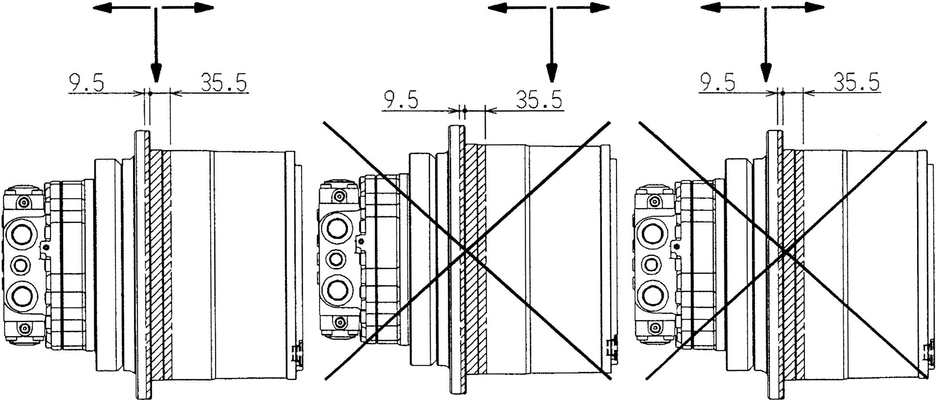
Section B
Section B, machine main unit driven side frame
Machine main unit driven side frame should be chamfered by C3 or more.
Like wheel type machines, a machine where the working position of load of the driven section significantly diverged is not applicable
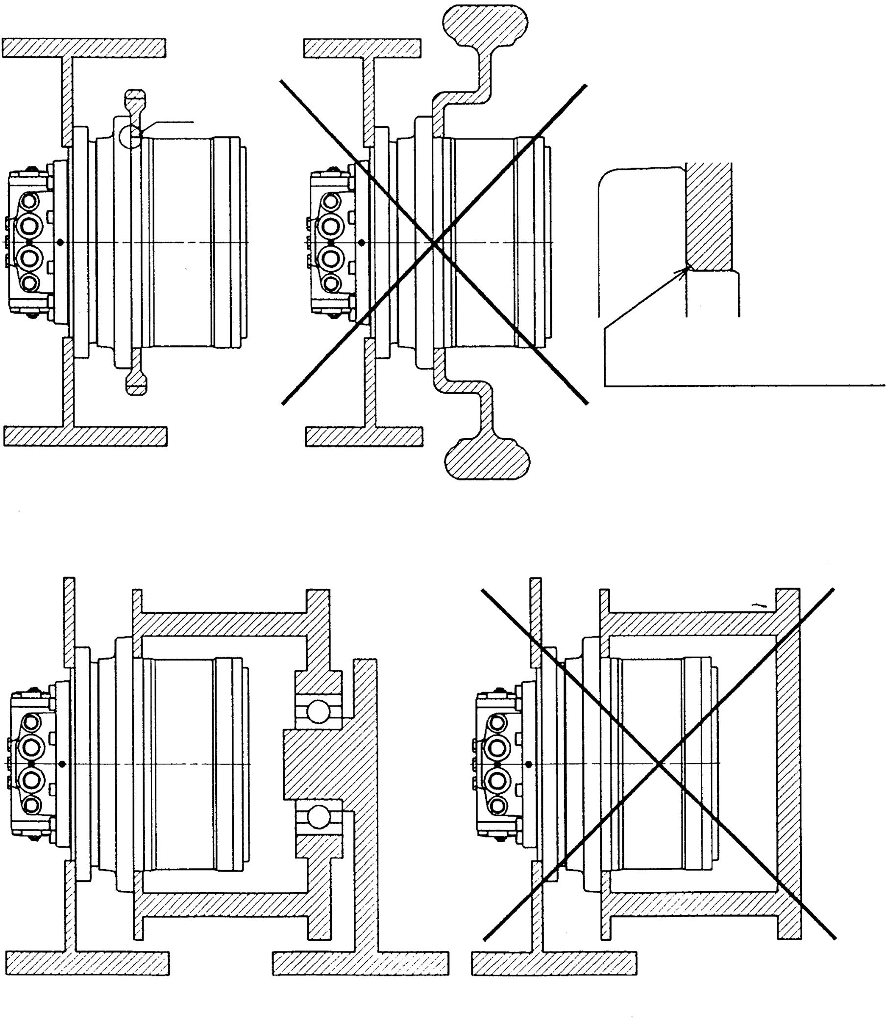
Setting up the bearing in the position appropriate for the motor
Figure 25. Installation of the machine main unit driven section
[6]Pipe installation 1. Piping and the motor rotation direction
Before performing piping, make sure the motor rotation direction determined by the combination of the inflow port and the outflow port for hydraulic oil. Table 15 and Figure 26 show the motor rotation direction determined by the combination of the inflow port and the outflow port for hydraulic oil.
Table 15. Motor Rotation Direction Determined by the Combination of the Inflow Port and the Outflow Port for Hydraulic Oil
Hydraulic Oil Inflow Port Hydraulic Oil Outflow Port Motor Rotation Direction (Rotation direction viewed from ) P1 port P2 port C direction (clockwise direction) P2 port P1 port A direction (anticlockwise direction)
Important If the pipes are incorrectly installed, the motor will rotate in the unintended, opposite direction, creating a highly dangerous situation. Make sure to check the pipe port positions and the motor rotation direction before carrying out piping.
A direction (anticlockwise direction) rotation C direction (clockwise direction) rotation
Figure 26. Motor rotation direction determined by the combination of the inflow port and the outflow port for hydraulic oil
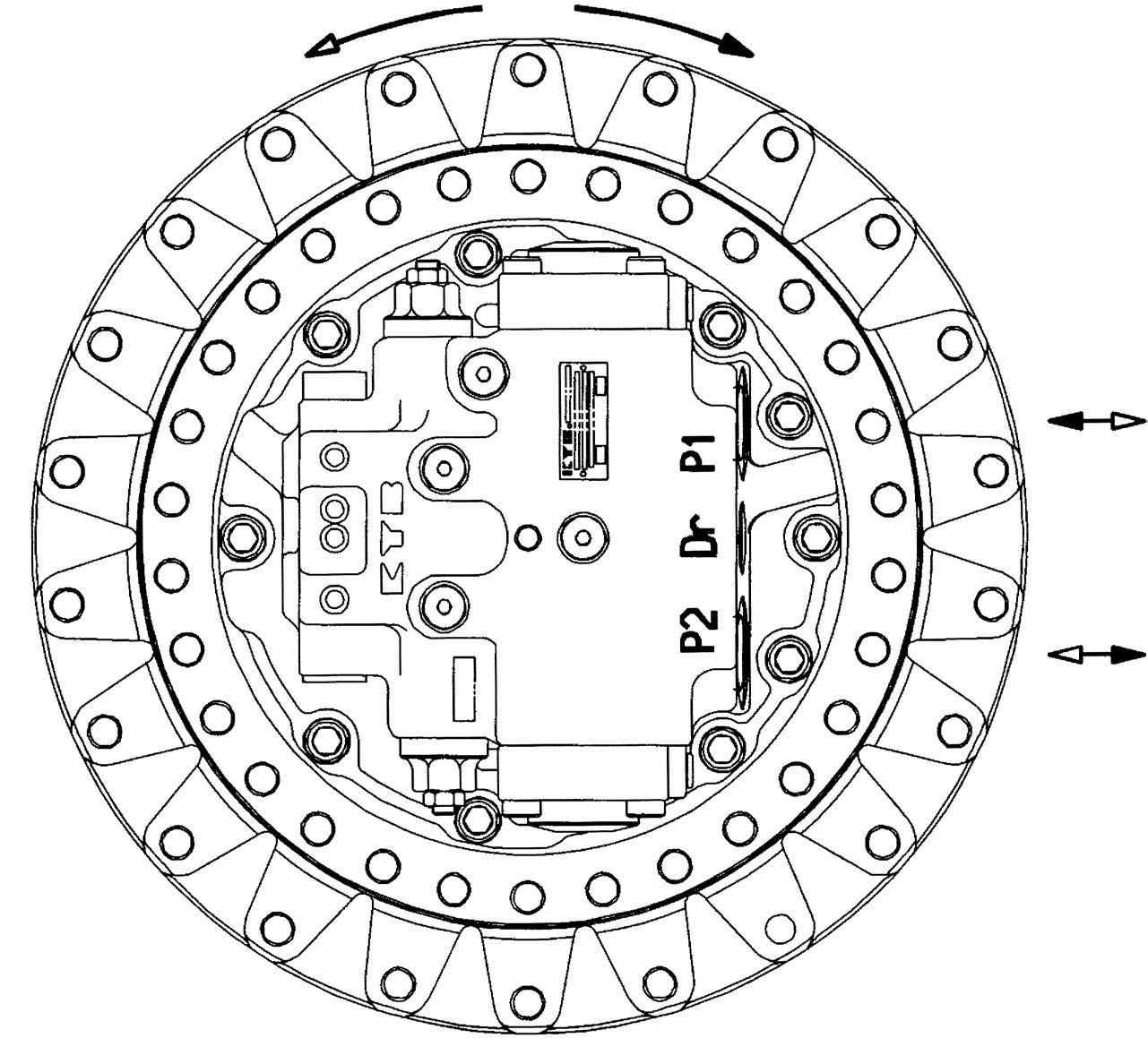
2. Positional relationship between the motor and the hydraulic tank On valves such as the piston motor valves and the double counter balance valve, there are slight leaks from their slits. Therefore, leaving the motor stopped for a long period of time may cause the hydraulic oil to leak from and air to accumulate in the motor circuit or the hydraulic circuit. Air in the circuit may cause a malfunction such as runaway phenomena upon starting of the motor after a long period of neglect. To prevent such an accident, place the hydraulic tank above the hydraulic motor in order for the hydraulic oil not to leak from the circuit.
Important If the hydraulic tank needs to be placed below the motor due to space or other limitations, make sure to set up a self-supply circuit and fill it with hydraulic oil before running the motor.
Hydraulic tank
Hydraulic tank
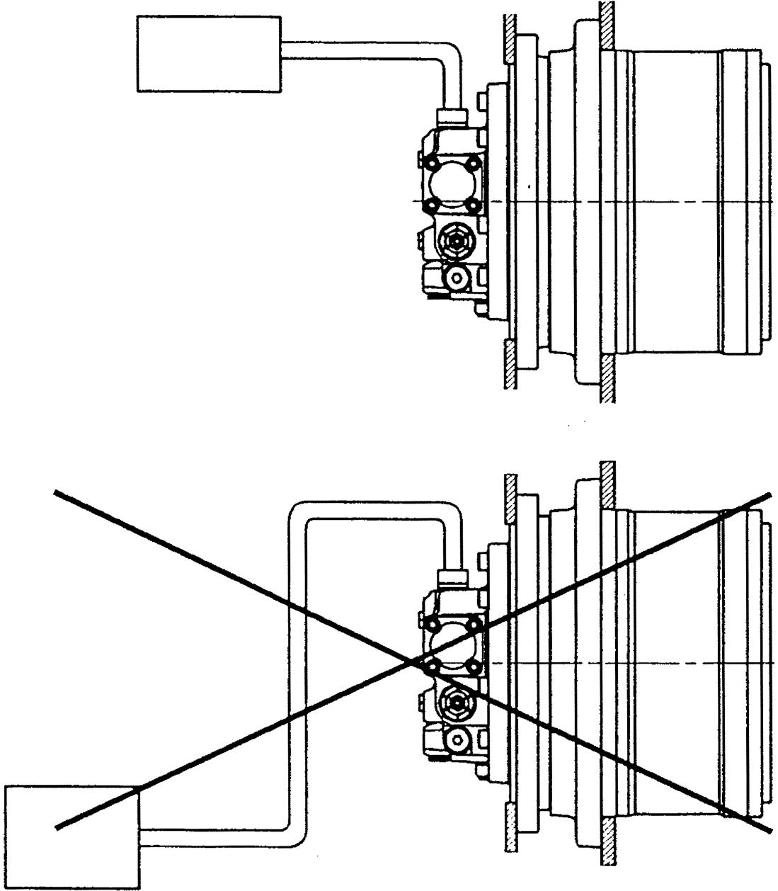
Figure 27. Positional relationship between the motor and the hydraulic tank
3. Piping configuration 1) Main pipe Set up the main pipe of the motor in the horizontal position or in the upright position. (See Figure 28). If the pipe is set up below the horizontal position and left stopped for a long period of time, the hydraulic oil may leaks from and air may accumulate in the motor circuit, causing aeration or cavitation resulting in a malfunction such as runaway phenomena on starting the motor.
2) Drain pipe The piston motor case must always be filled with hydraulic oil. Therefore, If there are two oil drain ports, use the upper one for drain piping (See Figure 28). If there is only one oil drain port, use it for piping.
1.Parking brake cannot be released due to the pressure in the motor case. In this case, brake dragging will occur, causing fatal damage to the parking brake functions. 2.The pressure rise in the motor case will cause damage to the oil seals and fatal damage to the piston motor section.
Important Be sure to perform drain piping. Failing to do so may cause the following problems due to rising pressure in the motor case:
Perform drain piping using either T1 or T2. Perform drain piping using the upper port (T1 or T2).
Top
Bottom
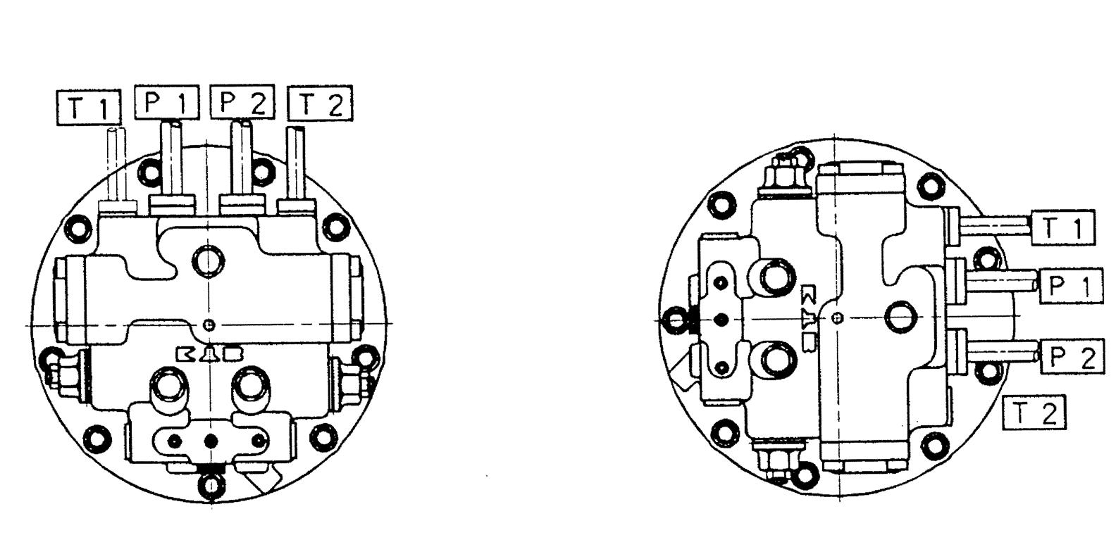
Figure 28. Piping to the motor
Bottom
3) Piping work The piston motor is sensitive to foreign matter in the hydraulic oil. Therefore, acid wash inside the pipes to thoroughly eliminate the foreign matter such as scales in the pipes before starting piping work. Be careful not to let any foreign matter, such as dust and sand, enter into the piston motor from pipe port section during piping work. Make sure to tighten each pipe with a torque specified in Table 16. If there are specifications defined by the manufacturer of the machine main unit, follow them.
Table 16. Tightening Torques for Pipe Ports
After piping work, flush inside the pipe line.
Pipe Port Name Port Size Specified Tightening Torque Port P1 and P2 PF3/4 372±20 N•m Port T1 and T2 PF1/2 92.2±3.9 N•m Port Ps PF1/4 22.6±1.0 N•m
12.Operation Check
After installing the new motor or the motor that had a maintenance check to the machine main unit and completing the piping work, perform an operation check using the following procedure before production run. [1]Preparation for operation check
1. Feeding hydraulic oil into the piston motor case
Before performing an operation check, feed about 500 cc of hydraulic oil from the oil drain port of the piston motor into the piston motor case to prevent initial failure that could occur at the sliding sections of the piston motor. If a hand pump or a low capacity electric pump is used for feeding, then the pressure in the piston motor case should be 0.3 MPa or lower.
2. Checking the reduction gear lubricating oil
Use the feed, drain, and oil check port shown in Figure 23 to make sure that the specified amount of lubricating oil is in the reduction gear case.
How to check the amount of the lubricating oil in the reduction gear of the new motor Remove the plug form the oil check port for lubricating oil and check to see whether the lubricating oil flows off. If the oil flows off, put the plug on the port and tighten to the specified torque. If the oil does not flow off, open the oil fill port and feed reduction gear lubricating oil until the oil flows from the oil check port. After oil feeding, put the plugs on the feed and oil check port and tighten to the specified torque. Caution As the lubricating oil, a given amount (3.5 L) of diamond hypoid gear oil 90 from Mitsubishi Oil has been fed by the factory setting.
Reduction gear lubricating oil Oil fill port
Lubricating oil level Reduction gear lubricating oil Oil check port
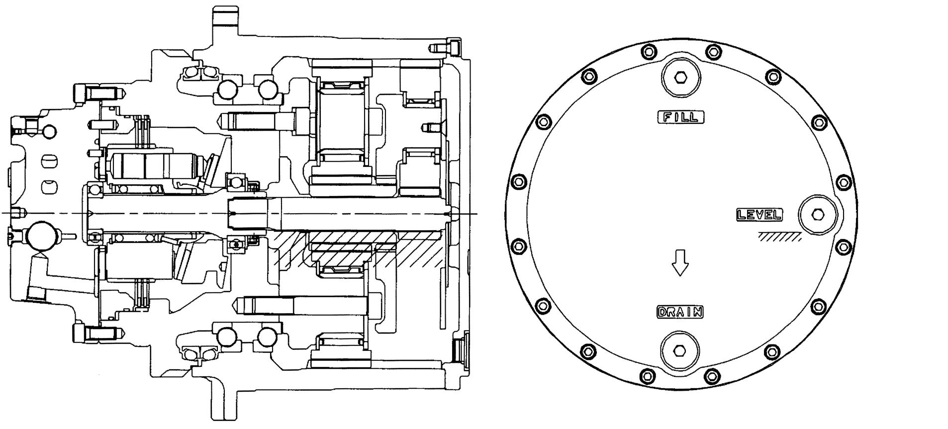
Reduction gear lubricating oil Oil drain port
Figure 29. Feed, drain, and check ports for the reduction gear lubricating oil and specified oil amount
[2]Operation check for the motor
Following the instructions in the operator’s manual for the machine main unit, slowly operate the machine and bleed off air from the motor circuit and the pipes.Start with a low speed rotation and repeat the operation of "C direction rotation, stop, A direction rotation, and stop" several times to check the operation. At this point of time, abnormal noise may come from valves or other parts due to the air left in the circuits but while repeating the operation at low speed, the air will be bled out and the noise will be stopped. If the abnormal noise stops and does not start again after repeating operations, then there is no problem and the motor can be used. If the abnormal noise does not stop after repeating operations, replace the motor because there may be a problem with it.
Check for any oil leaking from the motor, the pipe port sections, the pipe parts, and the equipment. If there is any oil leaking, tighten the bolts and pipe connections from which oil is leaking to the specified torque again.
After completing this check, rise the pressure for under-load operation and confirm that there is no abnormal noise or vibration coming from the motor.
• If there is oil leaking and pipes or other parts need to be tightened, make sure to stop the operation of the hydraulic equipment before starting the work. • Oil leaking should be checked for while the motor is under low pressure. If the pressure on the motor is high and there is oil leaking, oil blowing out will occur, resulting in a dangerous situation.
Important
13.Production Run
[1]Starting the motor
Start the motor by following the instructions for the machine main unit. [2]Managing temperature of the hydraulic oil during a production run
During a production run, pay attention to the temperature of the hydraulic oil. When the temperature of the hydraulic oil becomes too high, deterioration of the oil will be accelerated and a malfunction or breakdown of the hydraulic equipment will be caused. Therefore, during continuous operation, keep the temperature of the hydraulic oils between -10 and +80°C. However, if the cumulative running time with above 80°C is within 100 hours, the motor can operate at up to 95°C.
Important When cumulative running time at over 80°C has reached 100 hours, be sure to replace the motor seal.
During a production run, the temperature of the lubricating oil will rise due to gear meshing, oil agitation, and parts sliding in the reduction gear. Running with high-temperature lubricating oil for a long period of time will cause earlier deterioration of the oil, shorter gear and bearing lives, and deterioration of the seal. Therefore, during continuous operation, keep the temperature on the surface of the reduction gear between -10 and +80°C (lubricating oil temperature: between -10 and +90°C).However, if the cumulative running time with a lubricating oil temperature of above 90°C is within 100 hours, the reduction gear can operate at up to 100°C.
Important When cumulative running time at over 90°C has reached 100 hours, be sure to replace the reduction gear seal.
14.Maintenance and Inspection
Perform maintenance and inspection of the motor regarding the following items, as long as the motor has no problem in operation. [1]Pre-operation Inspection
Perform a pre-operation inspection before starting the motor by using the information in Figure 30 and Table 17.
Table 17. Items and Tasks of a Pre-operation Inspection and Solutions
Inspection Item Inspection Task Solution
Oil leak from pipe parts Clean the pipe port section and check for oil leak from the section. If there is oil leaking, check to see whether the pipe ports have been tightened. If they have not been sufficiently tightened, tighten the pipe ports to the specified torque. In addition, check the oil amount in the hydraulic oil tank by following the instructions for the machine main unit. If the pipe ports are tightened enough, replace the pipe connections by following the instructions for the machine main unit.
Oil leak from alignment surface 1.Piston motor
Clean the alignment surfaces of the piston motor (see Figure 24) and check for oil leak. If there is oil leaking, check to see whether the bolts on the alignment surfaces are tightened. If the tightening is not enough, tighten bolts to the specified torque. In addition, check the amount of oil in the hydraulic oil tank by following the instructions for the machine main unit.
Leak of reduction gear lubricating oil 2.Reduction gear
Clean the alignment surfaces of the reduction gear (see
Figure 24) and check for oil leak. Clean the reduction gear floating seal section and check for oil leak. If the bolts are tightened enough, disassemble the motor and replace the seal by following the maintenance procedures. If there is oil leaking from the cover, remove the cover and apply liquid packing again by following the maintenance procedures. If there is oil leaking from the other parts, check the tightening for the parts. If the tightening is not enough, tighten them to the specified torque. If they are tightened enough, replace the seal. Check the amount of the lubricating oil in the reduction gear. If there is oil leak from the floating seal section, disassemble the reduction gear and replace the floating seal by following the maintenance procedures.
Plug looseness Oil leak check Bolt looseness check
Oil leak check
Oil leak check
Oil leak check
Oil leak check Bolt looseness check Pipe looseness Oil leak check
Bolt looseness check Plug looseness Oil leak check
Pipe looseness Oil leak check Plug looseness Oil leak check
Pipe looseness Oil leak check
Oil leak check Bolt looseness check
Plug looseness Oil leak check Plug looseness Oil leak check
[2]Routine inspection
Important • When starting routine inspection, make sure to stop the operation of the hydraulic device. • Do not start inspection immediately after stopping the operation of the hydraulic device.
During operation of the hydraulic device, the temperatures of the hydraulic oil and the hydraulic equipment rise. Therefore, touching the hydraulic oil and the hydraulic equipment immediately after operation can cause burns.
1. Routine inspection of temperature of the hydraulic oil
By nature, the hydraulic oil in the hydraulic device gradually deteriorates over time as it is used. In addition, once deterioration starts, it accelerates, which shortens the operation life of the hydraulic device and can cause more accidents. Therefore, for longer operation life of hydraulic device and trouble prevention, regularly check the deterioration of the hydraulic oil and replace the oil accordingly by following the instructions below.
Initial replacement During the operation of a new hydraulic device, sediments such as sludge is settled in the circuits and the tank. When hydraulic oil that has these sediments flows in the hydraulic device, the device may be damaged. Therefore, replace the hydraulic oil after around 500 hours have passed since the initial running.
Regular check and hydraulic oil replacement Then, regularly check the deterioration of the hydraulic oil at an interval of around 500 hours and replace the oil accordingly.
Check method and replacement standards There are two methods to check the deterioration of the hydraulic oil: an appearance check where the deterioration is judged from its appearance and property test where the deterioration is judged by analyzing the oil. For either method, to judge the condition of the oil, the used oil is compared with new oil.
Appearance check Perform an appearance check as part of a routine inspection performed at an interval of 500 hours. This method involves the following procedure: Sample hydraulic oil from the hydraulic oil tank in operation and put it into a test tube. Sample hydraulic oil again after stopping the operation of the hydraulic device and waiting for 24 hours. By this time, oil should be sampled from about 5 cm above from the bottom of the tank. Then compare it with new oil. Table 18 shows how to judge from the appearance.
Table 18. How to Judge from the Appearance
Appearance Smell Condition Solution Transparent and no color change Good Good Continue to use the oil
Transparent but light color Good Different oil is mixed Check viscosity. If good, continue to use the oil.
Turned to milky white Good Water bubble or moisture is included Turned to blackish brown Bad Deteriorated by oxidation Separate the moisture (hydraulic oil manufacturer) Replace the hydraulic oil
Transparent and has small black spots Good Foreign matter is included Filter the oil and then use it
Property test Perform a property test as part of a routine inspection performed at an interval of 1000 hours. In this test, the hue, specific gravity, ignition point, viscosity, and oxidation are measured. Because this test is difficult to perform in the field, it is recommended to sample 1 L of the hydraulic oil and ask the oil manufacturer or an analysis company to judge it. Just for reference, Table 19 shows possible changes in hydraulic oil properties and their causes but actions to be taken, such as reuse or replace the oil, should be determined based on the results of a property test.
Table 19. Possible Changes in Hydraulic Oil Properties and their Causes
Cautions for the hydraulic oil replacement When replacing the hydraulic oil, be careful not to leave the deteriorated oil and sludge or other sediments in the circuit and the tank. They can contaminate to the new oil. The same applies to a dirty filter. Therefore, when replacing the hydraulic oil, make sure to do all of these at the same time: cleaning the hydraulic tank, flushing the circuit, and replacing the filter.
Properties Changes Due to Deterioration and Contamination Causes and Investigation Items
Specific gravity Up
Deterioration of the hydraulic oil, inclusion of different oil Ignition point Drop Deterioration of the hydraulic oil, inclusion of different oil Hue Darker and less transparent Oxidation of the hydraulic oil, emulsification due to moisture inclusion, inclusion of metal powder
Viscosity Up or down
Oxidation Up Up by deterioration of the hydraulic oil, down by flushing oil or other substances Temperature rise of the hydraulic oil, inclusion of metal powder
Demulsification The degree of vapor emulsification is up Deterioration of the hydraulic oil
Antifoam More bubbling, bad babble Wear of the additive agen hydraulic oil t, deterioration of the
2. Routine inspection of the filter
Many contaminating particles attach to the hydraulic device before and during installation of it, and dirt is produced by wear and cavitation during operation. In addition, foreign matter in the air comes in through the air breather or from the seal section of the cylinder rod. Because these dirt and foreign matter are removed by the filter, the filter element is getting dirty over time as the hydraulic device is used. When the filter element clogs, the filter performance decreases and the filter eventually becomes useless. Therefore regular inspection and replacement are necessary. The filter should be replaced after 50 hours have passed since starting using the hydraulic device. After that, perform routine inspection at an interval of 250 hours, and replace the filter if it is severely clogged. Note that if a filter that has no differential pressure indicator with which clog state of the element can be determined from outside is employed, replace the element after 50 hours have passed since starting using the hydraulic device. After that, replace the element every 250 hours.
3. Routine inspection of the reduction gear lubricating oil
By nature the lubricating oil in the reduction gear gradually deteriorates over time as it is used. In addition, metal powder gradually accumulates in the lubricating oil due to the wear of the gear and the sliding sections in the reduction gear. Deterioration and foreign matter accumulation shorten the operation life of the reduction gear and cause more accidents. Therefore, to maintain the performance of the reduction gear for a long period of time, regularly inspect and replace the reduction gear lubricating oil.
Do not perform a routine inspection or replacement of the lubricating oil immediately after stopping the motor. The high temperatures of the reduction gear and the lubricating oil after running can cause burns. A routine inspection or replacement should be performed after three hours have passed since stopping the running.
Do not loosen the plugs for feed, drain, and inspection of the lubricating oil immediately after running. During running, the temperatures of the reduction gear and the lubricating oil rise and the air in the reduction gear expands. Therefore, when loosening any plug, hot lubricating oil can blow out, causing burns or blindness if it gets into the eye. In addition, the expanding air can pop out the plugs, causing injury or blindness if they hit the eyes. When loosening the plugs, make sure to confirm that the temperature of the reduction gear is low and follow the procedure below:
Important
Important
1.Confirm the temperature of the reduction gear is low enough.
Top Reduction gear lubricating oil Oil fill port Bleed out the air
3.Loosen the oil fill port by turning around it twice to bleed out the air.
Lubricating oil level Reduction gear lubricating oil Oil check port
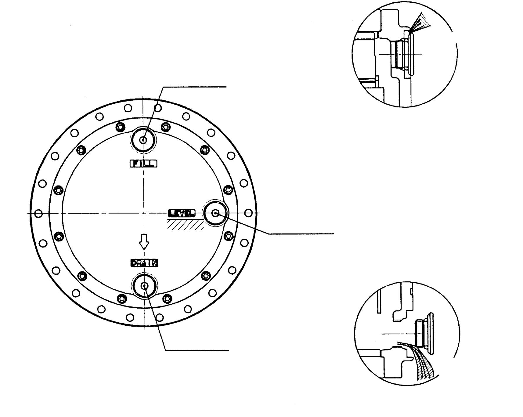
Bottom Reduction gear lubricating oil Oil drain port
2.Align the positions of feed, drain, and check ports for the lubricating oil.
Drain the lubricating oil
4.Slowly loosen the plug of the oil drain port to drain the lubricating oil.
Replacement timing for the reduction gear lubricating oil Reduction gear lubricating oil deteriorates over time as it is used and as metal powder enters it due to the wear of the gear and sliding sections. Therefore, periodically replace the reduction gear lubricating oil according to the numerical indication shown in Table 20.
Table 20. Replacement Timing for the Reduction Gear Lubricating Oil
When replacing the lubricating oil, be careful not to leave the deteriorated oil or metal powder in the reduction gear. They can be contaminants to the new oil. Therefore, before replacing the lubricating oil, thoroughly flush the inside of the reduction gear to remove the residual oil and metal powder. Routine inspection of the reduction gear lubricating oil The degree of the deterioration of the reduction gear lubricating oil also depends on the operation environment and the operation frequency. Therefore, regularly inspect the lubricating oil in addition to the replacement described above. As a way of performing a routine inspection, it is recommended to ask the lubricating oil manufacturer or an analysis company to analyze the used lubricating oil and comprehensively judge from the measured results of viscosity, total oxidation, iron, etc.
Table 21. Replacement Indication from the Results of Analysis
4. Routine inspection of the motor Using the motor for a long period of time will cause parts to wear and may result in performance degradation or failure. Keep logs about the routine inspection of the hydraulic oil and the reduction gear lubricating oil. If the property values of the oil indicate abnormal rise in the amount of foreign matter or if there is unusual foreign matter, disassemble and inspect the motor. In addition, disassemble and inspect the motor when the running time of it reaches 1000 hours or the number of start and stop times reaches 300000. Follow the maintenance procedures when disassembling and inspecting the motor. In particular, refer to the descriptions about wear of the parts including the parking brake disk in the maintenance procedures to replace the parts. The parking brake disk should be replaced when the number of action times reaches 300000.
Disassembly and inspection of the motor Follow the maintenance procedures when disassembling and inspecting the motor. Follow the maintenance standards described in the maintenance procedures when inspecting the motor during disassembly. Be sure to replace the seals when disassembling the motor.
Replacement Timing
Initial replacement 100 - 250 hours Second time replacement 1000 - 1500 hours
viscosity Change % Total Oxidation Heptane Insoluble Matter Iron % ±15 >2.0 >0.5 >0.1
Important Follow the instructions for the machine main unit when removing the motor from the machine. Remove the pipes after stopping the operation of the hydraulic device and release the air pressure in the tank to make the pressure equal to the atmospheric pressure.
<Company that can conduct property test for your routine inspection of the hydraulic oil and the reduction gear lubricating oil> An affiliate of KYB Co., Ltd., Japan Analist Co., Ltd. conducts oil analysis.
Routine inspection and replacement timing
Pre-operation Inspection
Pipe looseness
Bolt looseness
Oil leaking
Hydraulic oil
Filter
Reduction gear lubricating oil
Motor
Initial replacement 500 hours Routine inspection Appearance check Every 500 hours Property test Every 1000 hours
Initial replacement 50 hours Routine replacement Every 250 hours
Initial replacement 100 - 250 hours Routine inspection Every 1000 hours Routine replacement 1000 - 1500 hours
Routine inspection Every 1000 hours Seal replacement During routine inspection When the cumulative running time at over 80°C has reached 100 hours Parking brake disk replacement After the brake has been operated 300000 times and depends on the maintenance procedures
Bearing replacement Motor bearing Depends on the maintenance procedures
Needle bearing for the reduction gear
Depends on the maintenance procedures Angular bearing Depends on the maintenance procedures Other parts Depends on the maintenance procedures
15.Troubleshooting
If any kind of trouble occurs during a motor running, use the following troubleshooting information to investigate it and take countermeasure actions for it.
[1]Troubleshooting for piston motor
Trouble Description
Motor does not rotate.
The rotation speed of the motor is not enough. Possible Cause Countermeasure and Solution
Malfunction has occurred with equipment other than the piston motor and the reduction gear.
The motor itself has a problem and the operation section is clogged up with dirt causing malfunction.
Pressure on the intake side of the motor is low.
The sliding section of the piston motor has abnormally worn and the pressurized oil is escaping.
The main part of the piston motor is damaged. In this case, abnormal noise comes from the piston motor.
Too much load on the piston motor causes the relief valve to operate.
Due to a problem with hydraulic pump, the pressure control valve, the flow control valve, or other parts, the specified amount of flow does not enter into the piston motor, resulting in the insufficient rotation speed.
Wear of the sliding section of the piston motor causes the pressurized oil to flow from high-pressure side to low-pressure side (reduce volume efficiency), resulting in the insufficient rotation speed.
A loosened tightening bolt on the base plate of the piston motor increases internal leakage and results in the insufficient rotation speed. Check whether pressure has reached to the intake side of the motor and then inspect and repair the motor by identifying the causes of problems and countermeasures for it for each piece of equipment.
Disassemble and clean the unit to remove dirt and re-assemble it. If any part has been damaged by dirt, replace it.
Use the main relief of the circuit to rise the set pressure.
Disassemble the unit to replace the abnormally worn part. Remove any scratches or burr on the surface, clean the part, and re-assemble the unit.
Disassemble the unit to replace the damaged part. Clean the part, and reassemble the unit.
Investigate the load condition and adjust the load to the set pressure of the relief valve.
Check whether the specified amount of flow providos into the piston motor and then inspect and repair the motor by identifying the causes of problems and countermeasures for it for each piece of equipment.
Disassemble the piston motor to check the wear state of the sliding section and repair or replace it by following the maintenance procedures.
Retighten the tightening bolt on the base plate to the specified torque.
Trouble Description
The motor has a great rotation fluctuation. Possible Cause Countermeasure and Solution
A worn sliding section of the piston motor causes high-pressure oil to flow out from the oil drain port and the extremely reduced rotation speed results in the rotation fluctuation. Disassemble the unit to check the wear state of the sliding section and repair or replace it by following the maintenance procedures.
A hunting occurred at the double counter balance valve when going down a slope results in the rotation fluctuation.
Loud noise The shaft axial alignment may have a problem and the driven part touching the shaft generates noise.
A worn or damaged bearing, spring, or other part of the piston motor generates noise.
Oil leak A loosened bolt on the alignment surface or other place causes oil leak.
A damaged oil seal, O-ring, packing, or other seal causes oil leak.
A worn sliding section of the piston motor increases drain volume and the damaged oil seal causes oil leak.
A clogged or long and narrow drain pipe rises the drain pressure and the damaged oil seal causes oil leak. Disassemble the unit to check the wear state of the double counter balance valve and repair or replace it by following the maintenance procedures.
Precisely align the shaft axis.
Disassemble the unit to replace the damaged bearing, spring, or other part. Clean the parts and re-assemble the unit.
Retighten the tightening bolt to the specified torque.
Disassemble the unit to replace the seal. Check the temperature of the hydraulic oil. When the temperature of the hydraulic oil in operation is above 80°C, review the cooler and reduce the temperature of the hydraulic oil to below 80°C.
Disassemble the unit to check the wear state of the sliding section and repair or replace it by following the maintenance procedures. Replace the oil seal. Clean the part, and re-assemble the unit.
Disassemble the unit to replace the oil seal. Clean the drain pipe to remove any foreign matter. Review the piping system and reduce the pipe line resistance.
Trouble Description
Abnormal noise, rotation fluctuation, or pressure fluctuation occurs due to cavitation.
Motor rotation stopped during running. Possible Cause Countermeasure and Solution
The volume of the hydraulic oil in the hydraulic tank has been reduced and air taken in it causes aeration.
Improper orientation of the motor installation or improper position of the hydraulic tank causes hydraulic oil to bleed from the motor pipes or circuit while the hydraulic device stops operation and aeration occurs in the motor immediately after starting the motor.
When pumping action occurs in the piston motor, malfunction of the double counter balance valve causes vacuum on the intake side and results in cavitation.
Too much load caused the engine to stall.
Scorching on the sliding section of the piston motor causes the motor rotation to stop. Check the amount of the hydraulic oil in the hydraulic tank and feed hydraulic oil by following the instructions for the machine main unit.
Check the orientation of the motor installation and reinstall the motor in the correct orientation. Make sure that the oil level in the hydraulic tank is in an upper position than the motor. Change the position to the correct one. Alternatively, set up a self-supply circuit so that the motor circuit and the pipes will be filled with hydraulic oil.
Disassemble the unit to repair or replace the double counter balance valve by following the maintenance procedures.
Review load conditions and correct the value.
Refer to the specifications (especially for flow and motor speed). If the motor speed exceeds the limit, reduce the flow. Because the inside of the motor may be non-reusable state, replace the motor.
[2]Troubleshooting for parking brake
Trouble Description
While the motor is stopped with an external load on it, the motor rotates.
Motor drive force is not delivered. The motor section is abnormally hot. Possible Cause Countermeasure and Solution
A worn disk reduces the torque of the parking brake.
Contact defect or other problem deteriorates the disk surface and reduces the parking brake torque.
A fatigued or damaged spring reduces the parking brake torque.
The external load is too much for the parking brake capacity.
A damaged O-ring causes the pressurized oil to escape and the parking brake cannot be released.
A clogged orifice of the oil path for parking brake release prevents the pressurized oil from entering to the parking brake cylinder chamber and the parking brake cannot be released.
A clogged or long and narrow drain pipe rises the drain pressure and the parking brake cannot be released. Disassemble the unit to replace the parking brake disk. Clean the part, and re-assemble the unit.
Disassemble the unit to replace the disk. In addition, repair the surface of the counterpart of the disk and re-assemble the unit.
Disassemble the unit to replace the spring. Clean the part, and re-assemble the unit.
Review the external load and correct the value.
Disassemble the unit to replace the Oring. Clean the part, and re-assemble the unit.
Disassemble the unit to remove the foreign matter in the orifice. Clean the part, and re-assemble the unit. In addition, flush inside the pipe.
Clean the drain pipe. In addition, review the piping system and reduce the pipe line resistance.
[3]Troubleshooting for relief valve
Trouble Description
Motor does not rotate. Or, the rotation is slow.
Motor does not stop. Or, it takes a long time to stop.
Big shock occurs when stopping running. Possible Cause Countermeasure and Solution
Foreign matter gotten in between the poppet seat and the poppet of the relief valve causes seat defect and high pressure oil leaks to the low-pressure side. Disassemble the unit to remove the foreign matter. Clean the part, and reassemble the unit.
A broken spring of the relief valve causes the high pressure oil to leak to the low-pressure side.
A fatigued spring of the relief valve reduces the set pressure and a relief operation occurs at a low pressure.
Foreign matter gotten into the seat section between the free piston and the base plate of the relief valve reduces the set pressure.
A clogged orifice set to the poppet of the relief valve reduces the set pressure.
Foreign matter gotten in between the poppet seat and the poppet of the relief valve causes seat defect and the relief valve cannot close. Replace the relief valve. Disassemble the motor to clean the parts and re-assemble it.
Replace the relief valve.
Uninstall the relief valve to remove the foreign matter.
Uninstall the relief valve to remove the foreign matter.
Disassemble the unit to remove the foreign matter. Clean the part, and reassemble the unit.
The spring of the relief valve is broken and the relief valve cannot close.
A fatigued spring of the relief valve reduces the set pressure and the brake capacity is lowered.
Foreign matter gotten into the seat section between the free piston and the base plate of the relief valve reduces the set pressure and the brake capacity is lowered. Replace the relief valve. Disassemble the motor to clean the parts and re-assemble it.
Replace the relief valve.
Uninstall the relief valve to remove the foreign matter.
A clogged orifice set to the poppet of the relief valve reduces the set pressure and the brake capacity is lowered. Uninstall the relief valve to remove the foreign matter.
Foreign matter gotten into the sliding section of the poppet prevents the poppet from moving.
Foreign matter gotten into the free piston prevents it from moving. Replace the relief valve.
Uninstall the relief valve to remove the foreign matter and re-assemble it.
The set pressure of the relief is too high. Replace the relief valve.
[4]Troubleshooting for counter balance valve
Trouble Description
Motor does not rotate. Or, the rotation is slow.
Motor does not stop. Or, it takes a long time to stop.
External load works on the motor and rotation fluctuation arises when a pumping action is performed. Possible Cause Countermeasure and Solution
Pressurized oil has not reached to the intake of the motor and the plunger does not switch.
Pressure has reached to the intake of the motor but a clogged orifice of the pilot oil path prevents the plunger from switching. Check whether pressurized oil has reached to the intake side of the motor and then inspect and repair the motor by identifying the causes of problems and countermeasures for it for each piece of equipment.
Measure the pressure on the return side of the motor circuit to make sure that the pressure has risen. Disassemble the unit to remove the foreign matter. Then re-assemble the unit.
Foreign matter gotten into the plunger prevents it from switching.
Foreign matter gotten into the plunger prevents it from recovering and the brake capacity is lowered.
A broken spring of the plunger prevents it from recovering and the brake capacity is lowered.
A clogged orifice of the pilot oil path prevents the plunger from recovering or makes it take longer time to recover. Disassemble the unit to remove the foreign matter. Check the degree of the damage by following the maintenance procedures. If it is still usable, re-assemble it. If there is a serious damage, replace it by using the base plate kit.
Disassemble the unit to remove the foreign matter. Check the degree of the damage by following the maintenance procedures. If it is still usable, reassemble it. If it is no longer usable, replace it by using the base plate kit.
Disassemble the unit to remove the foreign matter and then replace the spring.
Disassemble the unit to remove the foreign matter. Then re-assemble the unit.
No spring is set in the plunger. Assemble a spring appropriately.
No check valve is set in the plunger. Assemble a check valve appropriately. The spring of the check valve is damaged. Disassemble the unit to remove the foreign matter and then replace the spring.
No spring is set in the check valve. Assemble a spring appropriately.
Foreign matter gotten into the plunger prevents it from moving smoothly. Disassemble the unit to remove the foreign matter. Clean and re-assemble the unit.
The orifice bore of the pilot oil path is wrong. Assemble an appropriate orifice in the pilot oil path.
No orifice is set in the pilot oil path. Assemble an orifice in place.
Trouble Description
External load works on the motor and cavitation and abnormal noise occur when a pumping action is performed. Possible Cause Countermeasure and Solution
Foreign matter gotten into the plunger prevents it from moving smoothly and providing counter balance function.
The spring of the plunger is damaged and the counter balance function is not provided.
No spring is set in the plunger and the counter balance function is not provided.
The spring of the check valve is damaged and the counter balance function is not provided.
No spring is set in the check valve and the counter balance function is not provided.
The orifice of the pilot oil path is clogged with foreign matter and the counter balance function is not provided. Disassemble the unit to remove the foreign matter. Check the degree of the damage by following the maintenance procedures. If it is still usable, re-assemble it. If it is no longer usable, replace it by using the base plate kit.
Disassemble the unit to remove the foreign matter, replace the spring, and re-assemble the unit.
Assemble a spring appropriately.
Disassemble the unit to remove the foreign matter and then replace the spring.
Assemble a spring appropriately.
Disassemble the unit to remove the foreign matter and re-assemble it.
Trouble Description
Does not switch to the high-speed rotation.
It switches to the high-speed rotation but switches to the low-speed rotation when the temperature of the hydraulic oil rises. Possible Cause Countermeasure and Solution
Pilot pressure oil has not reached to Ps port.
Foreign matter gotten into between the spool and the base plate prevents the spool from switching.
Abnormal wear in the 2nd-speed control piston section causes pressurized oil leak in the case. Check whether pilot pressurized oil has reached to the Pa port and then inspect and repair the motor by identifying the Causes of problems and countermeasures for it for each piece of equipment.
Disassemble the unit to remove the foreign matter. Check the degree of the damage by following the maintenance procedures. If it is still usable, reassemble it. If it is no longer usable, replace it by using the base plate kit.
Disassemble the unit to replace by using the flange holder kit.
No 2nd-speed control piston is set. Assemble a 2nd-speed control piston in place.
A clogged orifice of the 2nd-speed oil path prevents pressurized oil from reaching to the 2nd-speed control piston. Disassemble the unit to remove the foreign matter and re-assemble it.
Abnormal wear in the 2nd-speed control piston section causes pressurized oil leak in the case. Disassemble the unit to replace by using the flange holder kit.
Does not switch to the low-speed rotation.
It switches to the low-speed rotation but switches to the high-speed rotation during running. The pressure of the Ps port dose not decrease after setting the speed control switch to low speed.
The spring of the 2nd-speed valve is damaged.
No spring is set in the 2nd-speed control valve.
Foreign matter gotten into between the spool and the base plate prevents the spool from returning.
A clogged orifice of the 2nd-speed oil path prevents the pressure in the 2ndspeed piston chamber from being released.
A fatigued spring of the 2nd-speed valve reduces the switchover pressure.
A clogged pilot pipe causes leak from 2nd-speed control valve and the pilot pressure rises to the switchover pressure. Make sure that the pressure of the Ps port is 0.5 MPa or less and review the piping system.
Disassemble the unit to remove the foreign matter and then replace the spring.
Assemble a spring in place.
Disassemble the unit to remove the foreign matter. Check the degree of the damage by following the maintenance procedures. If it is still usable, re-assemble the unit. If it is no longer usable, replace it by using the base plate kit.
Disassemble the unit to remove the foreign matter and re-assemble it.
Disassemble the unit to replace the spring.
Clean the inside of the pipe to remove the foreign matter. In addition, review the piping system.
[6]Troubleshooting for reduction gear
Trouble Description Possible Cause Countermeasure and Solution
No rotation. Malfunction has occurred with equipment other than the piston motor and the reduction gear. Check whether pressure has reached to the intake side of the motor and then inspect and repair the motor by identifying the causes of problems and countermeasures for it for each piece of equipment.
Malfunction has occurred with the motor except the reduction gear.
A load that exceeds the motor output torque is working on the motor.
The angular bearing of the reduction gear is damaged and does not rotate. See the above-mentioned troubleshooting 1 through 5.
Check the load working on the motor and remove it.
Replace the reduction gear. Check whether too much external load is working on it. If so, remove the load.
The gear in the reduction gear is damaged and does not rotate.
The bearing in the reduction gear is damaged and does not rotate. Replace the reduction gear.
Abnormal noise comes from the reduction gear during running. The spline in the reduction gear is damaged and does not rotate.
The gear in the reduction gear is damaged.
The bearing in the reduction gear is damaged.
The sliding section of the reduction gear has worn and interference has occurred among the parts. Replace the reduction gear.
Disassemble the unit to check the damage. If damaged, replace the reduction gear. If it is not damaged, replace the worn parts. Clean the reduction gear and reassemble it.
The attachment section of the reduction gear is abnormally hot. The reduction gear lubricating oil is not enough.
The reduction gear lubricating oil is too much.
The bearing in the reduction gear is damaged.
Wrong selection of a thrust plate causes abnormal thrust load in the reduction gear. Check whether there is any oil leak point. Disassemble the reduction gear to check internal damage. If damaged, replace the reduction gear. Feed the specified amount of lubricating oil.
Adjust the amount of the lubricating oil to the specified amount.
Replace the reduction gear.
Disassemble the reduction gear to check internal damage. If damaged, replace the reduction gear. If not damaged, replace the thrust plate with one with appropriate thickness.
Trouble Description
There is oil leaking. Possible Cause Countermeasure and Solution
A loosened tightening bolt on the reduction gear cover causes oil leak. Remove the cover to apply liquid packing again and then tighten the cover to the specified torque. Feed the specified amount of lubricating oil.
A loosened plug of the feed, drain, or oil check port on the reduction gear cover causes oil leak.
A deteriorated O-ring of the feed, drain, or oil check port on the reduction gear cover causes oil leak. Retighten the plug to the specified torque. After that, feed the specified amount of lubricating oil.
Replace the O-ring of the plug. After that, retighten the plug to the specified torque and feed the specified amount of lubricating oil.
cracks on the housing causes oil leak. Replace the reduction gear.
Foreign matter gotten into the sliding surface of the floating seal causes oil leaking.
Corrosion on the sliding surface of the floating seal causes oil leak.
A deteriorated or damaged O-ring of the floating seal causes oil leaking. A cracked seal collar of the floating seal causes oil leak. Disassemble the unit to remove the foreign matter from the floating seal and re-assemble it.
Disassemble the reduction gear to replace the floating seal.
16.Motor Repair Kit
See the attached parts list for the content of the repair kit.