16 minute read
2 210 X2 Assembly and Disassembly of Swing Unit


Caution
1.Before starting disassembly, re-assembly, inspection or repair work, read this maintenance manual thoroughly and be sure you understand its contents. 2.Handle this product according to the separate "Usage Precautions". 3.Stop the equipment system this product is mounted on and wait for the surface temperature of this product to fall to about 40°C or less before removing this product from the equipment it is mounted on. Working on this product while it is still hot may result in burns. Whenever removing a pipe from this product, be sure to bleed the pressure. Removing a pressurized pipe without bleeding pressure inside can induce a blow out of oil, resulting in personal injury and oil leakage. 4.Use the special tools and measuring instruments when disassembling, re-assembling, inspecting or repairing this product. Using an inappropriate tool may result in burns and damage to the product. 5.Be careful not to drop parts when assembling, re-assembling, inspecting or repairing this product.
Otherwise, personal injury or property damage may result. 6.Do not touch machined edges or threaded sections of parts directly with your bare hands when disassembling, re-assembling, inspecting or repairing this product. Doing so may result in personal injury. 7.After re-assembly, check the performance of the product. Do not use the product unless the performance has fully recovered. Otherwise, damage may result to the equipment. 8.The caution (mark !) in this maintenance manual does not encompass all cases. Be sure to act on the safety-first principle whenever disassembling, re-assembling, inspecting, repairing, etc. this product.
1. Usage Precautions (1)How to Handle the Product When transporting or storing this product, be sure to handle it with the output shaft directing downward and placing the product in an upright position. Whenever lifting a unit, screw in a clean lifting tool to the make-up port (G1) at the motor cover center to lift the unit using this lifting tool. In particular, do not try to lift the relieve valve by hanging a wire on it. Otherwise, excessive load will be applied to the valve, deforming it and, thus inducing its malfunction. (2)Pipes Dimensions required for the pipe fittings are previously determined from the external shape diagram. A hose or steel pipe must be used as the pipe. Make sure it is shaped in such a way that excessive force is not applied to the pipe installation position. In addition, before laying a pipe, be sure to remove the rubber cap seal on the port. A large diameter pipe must be used for the drain pipe in order to reduce pressure in the motor case. Reasonable care must be exercised when connecting the drain pipe to a return pipe of another piece of equipment, since a sudden inflow or outflow of oil can induce abnormal back pressure in the motor case, damaging the oil seal and other components. Set the pressure in the motor case in such a way that the peak pressure remains at a maximum of 0.3 MPa. (3)Hydraulic Oil, Grease and Gear Oil
Hydraulic oil Recommended hydraulic oil: ISO VG#32 - 56 or equivalent wear-resistant mineral oil type hydraulic oil that satisfies the following viscosity and temperature requirements. Recommended operating viscosity range:10 - 200 mm2/s Maximum allowable viscosity at start: 1000 mm2/s Allowable operating temperature range:-30 - +95°C Note: Contact us when using biodegradable hydraulic oil. Biodegradable hydraulic oil or hydraulic oil of low friction type can reduce the performance and durability.
Grease About 1 L of Shell Albania EP2 is filled in the delivered product. Be sure to use the above or equivalent when refilling or replacement is required. Refilling timing:250 hours for the first time It is recommended that grease is replaced every 1000 hours after that. Note: In the process of filling the grease, internal pressure can damage the oil seal on the reduction gear. Thus, it is necessary to open the plug of the air bleed port before beginning the filling.
Gear oil About 5 L of Hypoid Gear 90 from Shin Nihon Sekiyu is filled in the delivered product. (Up to the center of the level gauge) Be sure to use the above or equivalent when refilling or replacement is required. Allowable minimum viscosity:30 mm2/s Refilling timing:250 hours for the first time It is recommended that grease is replaced every 1000 hours after that.
(4)Preliminary Run
As the pipe laying is completed, flush the pipe sufficiently and then reconfirm the state of the installed parts along the circuit. Bleed air in the motor case and then fill it with hydraulic oil. Running the motor leaving the motor case empty may result in internal damage. After making sure that every thing is acceptable, run the motor without load and at a low speed for 10 to 15 minutes to make sure abnormal noises or vibrations do not occur. Then gradually increase the speed while applying load. (5)Mechanical Brake
Use the mechanical brake as the parking brake.
Its kinetic use or using it from a slipped state may result in abnormal wear on the brake plate. (6)Relief Valve
The following shows the relation between the relief valve set pressure and adjusting shims. If, however, confirmation of the set pressure is not available, do not try to make any adjustment.
Amount of adjustment available from shim of 0.1 mm Approximately 0.5 MPa
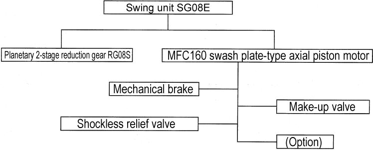
2. Equipment Configuration
3. Structure and Operating Principles (The numbers in parentheses correspond to those in the sectional structural diagram.) [1] Hydraulic motor The rotary group is made up of one-piece drive shaft and the cylinder (24) and 9 pistons assembly (7) positioned on the cylinder (24). Also, the cylinder (24) is supported at both ends with bearings (3) and (22). The piston assembly (7) is guided by the return plate (6) and receiving spring (4) so that it slides smoothly on the cam plate (5). Also, the balance plate (21) is pressed against the end of the cylinder (24) by the hydraulic pressure operating on the force of the Scrowave spring (18) and bushing (20). The mechanical brakes (8), (9), (11) and (13), that are used as the parking brakes, are provided in the space between the perimeter of the cylinder (24) and housing (25). And the relief valve (35) for the cushioning function and make up valves (38), (39) and (40) for the cavitation prevention are built in the cover (32).
[2] Explanation of hydraulic motor operation
Pressurized oil fed by the pump through the control valve or the like enters from A port (or B port) on the cover (32) and is discharged from the B port (or A port).
Also, the oil that has leaked through the sliding sections and the gap is returned to the hydraulic tank from the oil drain port "a" on the cover (32).
The pressurized oil fed to the A port is fed to cylinder (24) piston hole "f" through path "b" in the cover (32), path "c" of the bushing (20) section in the cover (32), the balance plate (21) path "d" that has a crescent shaped port that switches between feed and discharge every 180° of rotation of the motor, and the cylinder (24) path "e".
The pressurized oil operates on the piston assembly (7) and the piston assembly (7) is pressed against the cam plate (5) through the shoe. The cam plate (5) shoe sliding surface has a constant angle of inclination. Thus, the piston assembly (7) pressing force generated by the pressurized oil is converted into the force that slides the shoe on the swash plate. The piston assembly (7) shoe spherical section is coupled as a free joint, so the force that slides the shoe on the swash plate is transmitted to the motor output shaft section as rotation force through the cylinder (24).
In this way, each the piston assembly (7), receiving pressurized oil during its stroke from the top dead center to bottom dead center of the slope face, converts this hydraulic pressure force to rotation force to rotate the cylinder (24) and then discharge oil in the stroke from the bottom dead center to the top dead center. The discharge path is the reverse of the above pressurized oil feed path. Namely the oil is discharged from the B port.
In this way, the hydraulic motor is operated. The hydraulic motor output torque is determined by the hydraulic pressure force and speed is determined by the quantity of oil being supplied. [3] Explanation of reduction gear structure and operation
The power transmitted from the hydraulic motor output shaft is transmitted to the 2nd stage sun gear (72) through the 1st stage sun gear (76), planetary gear (79), and holder 1 (81). At the same time, the power is transmitted to the output shaft (61) via 2nd stage sun gear (72), planetary gear (84), and holder 2 (87). The output shaft (61) is supported in the gear case (66) by 2 bearings (65) and (71).
Also, in order to protect the output side bearing (65), which is exposed to severe load conditions, from gear wear powder, the oil seal (70) is provided at the center ion of the gear case (66). A chamber side is lubricated with gear oil, and the B chamber side is lubricated with grease. [4] Explanation of mechanical brake operation
The friction plate (8) is spline coupled with the periphery of the cylinder (24). Also, partner plate (9) is coupled with housing (25). When the mechanical brake release chamber pressure is zero, the brake piston (11) presses the friction plate (8) and partner plate (9) with the force of the spring (13) to lock rotation of the cylinder (24) (output shaft).
On the other hand, as oil pressurized to 3.2 - 4.9 MPa worked on the brake release chamber, the brake piston (11), overcoming the spring force, extends its stroke up to the cover (32) end face. This stroke generates a clearance between the friction plate (8) and partner plate (9), thereby releasing the mechanical brake.
[5] Explanation make-up valve operation (1) Half-brake state (The state in which the shockless relief valve (35) is disabled)
Decelerating the currently accelerated swing body by setting the control valve to the half lever position reduces supply of oil from the pump to the A port. However, if the swing body was rotating at a relatively high speed, the pressure comes close to negative at the "c" section due to the motor pump operation, so oil supply becomes necessary. However, if the B port pressure is lower than the operating pressure of the shockless relief valve (35), all the oil flowing into the "c" section from the A port is drained to the control valve via the B port, so with just the quantity of oil from the control valve, the quantity of oil is insufficient for what is absolutely required at the "c" section. (Since the valve is at the half lever position, the quantity of oil from the pump is restricted.) In order to prevent this, the make-up check valve (38) is provided so that the shortfall is supplied to the "c" section from the make-up port.
(2) When the brake operates (The state in which the shockless relief valve (35) is enabled) In the state of (1), if the lever is sharply operated to neutral, the quantity of oil fed from the pump to the A port becomes zero, but the swing body rotates due to inertial force. In this case, B port side the shockless relief valve (35) is enabled. The oil blown by the relief valve passes through oil paths "i" and "h"and pushes open A port side the make-up check valve (38), and is fed to oil paths "b" and "c", but the quantity of this oil falls short by the quantity of oil that leaked down the motor case drain. In order to prevent this from occurring, the make-up check valve (38) is opened from the make-up port to supply oil to oil paths "b" and "c" to prevent cavitation.
[6] Explanation of relief valve operation (Relief valve internal structure diagram) (1) At starting
The pressurized oil fed to the A port by the control valve does not run the motor at the constant rotation because the swing body inertial force is large. And part of the oil flows to B port passing through the shockless relief valve (35), which operates as a safety valve, oil paths "g" and "h" and pushing open B port side check valve (38). A port oil, overcoming the force of spring (47), flows to path "h" pushing open the poppet (46) and passing through path "g" between the seat (45) and poppet (46).
(2) When brake is applied (When the cushioning function is turned on) When the control valve is returned to neutral, the motor discharge oil return path is closed. Immediately after this operation, the motor is rotated with a large inertial force, causing it to function as a pump. This pumping action suctions oil from A port and then tries to discharge it from B port. But discharge of oil is not possible because the control valve return path is closed and, as the result, the B port pressure rises. The increased B port pressure pushes open the poppet (46) resisting the force of the spring (47). Thus, oil from B port flows through oil paths "i" and "h" and then flows into path "c" pushing open the make-up check valve (38). Through these processes the motor gradually comes to a stop absorbing inertial force of the swing body. Also, in the above pressure rise process, the pressurized oil in B port passes through the poppet (46) outer circumference orifice "j", through the small hole path at the center of the piston (51), and then enters the piston chamber, moving the piston (51) to the position where it contacts the end face of the liner (50). Since the poppet (46) has already been pushed open up to this point, the cushion action operates at first with somewhat low pressure and, within a very short span of time, rises to the specified pressure. This 2-stage operation provides the function for reducing the shocks resulting from starting or stopping the motor.
4. Disassembly [1] Apply an alignment mark on the unit alignment surface. It will facilitate re-assembling to apply an alignment mark on the alignment surface of the housing (25) and ring gear (73) by use of paint.
[2] Removal of level gauge assembly
Remove the level gauge assembly (42), cap (44) (27 mm diagonal hexagon socket head) and cap (34) (10 mm diagonal hexagon socket head).
*1 Alignment mark *1
[3] Draining of gear oil
Loosen the cap (90) (10 mm diagonal hexagon socket head) to drain gear oil.
•Gear oil is not reusable.
[4] Removal of motor
Loosen the hexagon socket head bolt (75) (6 mm diagonal hexagon socket head) to remove the motor along with the washer (74).
Lift and remove the motor by use of the makeup port (G1).
•The alignment surface of the housing (25) and ring gear (73) is coated with liquid packing. Thus, when removing the motor, use the notch shown in the figure to the right.
The above completes the disassembly procedure.
*1Notch *1
5. Assembly [1] Coating with liquid packing Clean and degrease the respective alignment surfaces of the ring gear (73) and motor housing (25), and then coat the surfaces with liquid packing ("1215" Gray from Three Bond or equivalent).
[2] Installation of motor
Lift the motor gently and assemble it to the reduction gear. Then tighten them using the hexagon socket head bolt (75) (19 mm diagonal hexagon) assembled with washer (74) at a tightening torque of 103 N•m.
•Assemble the housing (25) and ring gear (73) aligning their phase to the alignment mark that was applied prior to disassembly.
*1
*1Liquid packing application position
[3] Installation of level gauge assembly
Assemble the cap (44) (27 mm diagonal hexagon) to the housing (25) using a tightening torque of 49 N•m and then insert the level gauge assembly (42).
[4] Gear oil filling
Fill oil through the gear oil filler port on the housing (25).
[5] Grease up
Remove the cap (92) (6 mm diagonal hexagon) and the sunk plug (68) (5 mm diagonal hexagon) from the gear case (66) and then fill grease.
•In the process of filling the grease, internal pressure can damage the oil seal on the reduction gear. Thus, it is required to open the sunk plug (68) of the air bleed port before beginning the filling.
Tighten the cap (92) (6 mm diagonal hexagon) to the gear case (66) using a tightening torque of 29 N•m. Tighten the sunk plug (68) (5 mm diagonal hexagon) to the gear case (66) using a tightening torque of 20 N•m.
The above completes the assembly.
6. Maintenance Standard Table
Table 1
Part name Inspection and Measurement Location
Reference Value (Tolerance Limit Value) Measurement Device
Repair and Solution Procedure
Piston assembly (7) Shoe sliding surface roughness 0.8 S
Surface roughness gauge
Repair with sandpaper lapping Shoe sliding surface groove depth 0.4 mm min. Micrometer Replace with a new part. Play in piston and shoe spherical coupling section 0.4 mm max. Dial gauge Replace with a new part.
Piston bore Wear does not essentially occur. If damage or seizing is recognized, replace with a new part.
Cam plate (5) Surface roughness 0.8 S Surface roughness gauge Lap
Cylinder (24) End surface roughness 0.4 S Surface roughness gauge Lap
Piston hole Wear does not essentially occur. If damage or seizing is recognized, replace the motor.
Balance plate (21) Surface roughness 0.8 S Surface roughness gauge Lap
Piston assembly (7) Cylinder (24) Gap between piston bore and cylinder hole 0.04 mm max. Micrometer Air micrometer Replace the motor.
Table 2
Part Name Inspection and Maintenance Standard Tapered roll bearing (3) Needle bearing (22) Self-aligning roller bearing (65) Self-aligning roller bearing (71) The bearing must be replaced with a new one after every 3000 hours even if it is operating normally. And it must also be replaced with a new one when re-assembled after disassembly.
Oil seals (2) and (70)
O-rings (10), (12), (16), (30), (31), (36), (43), (91) and (93)
Backup rings (29) and (41) If there is any damage to the lip, replace it with a new part. Even if the oil seal is free from leakage or damage to the lip, it must be replaced with a new one after every 3000 hours. And it must also be replaced with a new one when re-assembled after disassembly. If any damage is recognized on an O-ring, replace it with a new part. Even if the O-ring is normal, it must be replaced with a new one after every 3000 hours. And it must also be replaced with a new one when re-assembled after disassembly. They must be replaced with new part when re-assembling after disassembly.
Aport
B port
Top dead center
Make-up port Oil drain port A port side relief
Bottom dead center
B port side relief MFC160Internal Structure Diagram
Mechanical brake release chamber
Relief Valve Internal Structure Diagram
RG08S Internal Structure Diagram
A chamber
B chamber