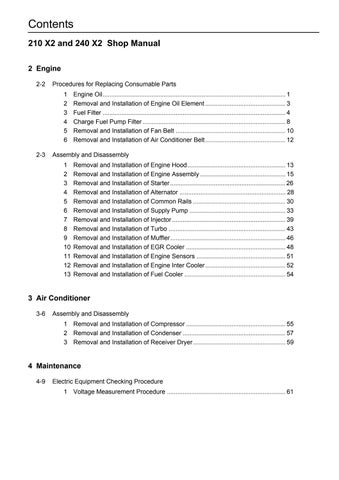
7 minute read
4Regulator Disassembly and Assembly Procedures


4 Regulator Disassembly and Assembly Procedures
1. Tools
The table below shows the tools required for the disassembly and assembly of
KR3G-9*04-HV.
B
Tool name and dimensions
Required tools are indicated with Part name
Name B
Hexagon socket head bolt (shouldered bolt) PT mounted valve (PT screw) ROH plug (PF screw)
Hexagon socket head stop screw
Hexagon bar wrench 2 - - - M4 2.5 - - - M5 3 - - - M6 4 M5 BP-1/16 - M8 5 M6 BP-1/8 - M10 6 M8 BP-1/4 ROH-1/4 M12 M14 8 M10 BP-3/8 ROH-3/8 M16 M18 10 M12 BP-1/2 ROH-1/2 M20 12 M14 - - 14 M16 M18 BP-3/4 ROH-3/4 17 M20 M22 BP-1 ROH-1 19 M24 M27 - - -
Closed wrench Socket wrench Double-head (single-head) wrench
22 - - VP-3/8 24 M16 M16 27 M18 M18 VP-1/2 30 M20 M20 36 - - VP-3/4 41 - - VP-1 46 M30 M30 - 50 - - VP-11/4 55 - - VP-11/2 Monkey wrench - Medium-sized × 1 Screwdriver - Medium-sized flathead screwdriver × 1 Pliers - For stop ring TSR-150 - For locking ring TRR-150 Torque wrench - With adjustable specified torque tightening Steel rod - Diameter φ4 or less L = 100 Hexagon socket head bolt - For pulling out adjusting ring M4, L = approximately 50
2. Disassembly Preparations [1]These regulators are configured with small precision parts, so disassembly and assembly requires rather complex operations. Read the entire section below on the maintenance procedures, and follow the procedure for disassembling the pump. [2]The pressure-flow settings of the front side regulator and rear side regulator differ, so mark the regulators when disassembling to differentiate between the drive side and the driven side. [3]The numbers in parentheses after the part names indicate the codes in the cross-section diagrams of Figures 1 and 2 (pages 9 and 10).
3. Disassembly Procedure [1] Select the location for disassembling the regulator. •Find a clean location to disassemble the regulator. •Place a rubber plate or cloth on the work table so as not to damage the parts. [2] Use cleaning oil to remove any dirt or rust from the surface of the regulator. [3] Remove the hexagon socket head bolt (438), and remove the cover (C) (629). •The cover (C) is assembled with an adjusting screw (C) (628), adjusting ring (C) (627), lock nut (630), hexagon nut (801), and hexagon socket head stop screw (924). Do not loosen these screws and nuts. Doing so changes the adjusted pressure-flow setting.
[4] After removing the cover (C) (629) subassembly, remove the outer spring (625), inner spring (626), and spring seat (C) (624) from the compensation section, and pull out the adjusting ring (Q) (645), pilot spring (646), and spring seat (644) from the pilot section. •The adjusting ring (Q) (645) can be easily removed by pulling it out with an M4 bolt.
Remove the pilot cover (641), and remove the pin 2 (898) and Pf sleeve (631) from the compensation section and the set spring (655) from the pressure adjustment section. [6] Remove the stop ring (814), and remove the spring seat (653), return spring (654), and sleeve (651). •The sleeve (651) is assembled with a snap ring (836). •When removing the stop ring (814), the return spring (654) flies out, so be careful not to lose this part.
[7] Remove the locking ring (858), and remove the fulcrum plug (614) and adjusting plug (615). •The fulcrum plug (614) and adjusting plug (615) can be easily removed by pulling them out with an M6 bolt.
[8] Remove the lever (2) (613). Do not pull out the pin (875). •This can be easily removed by using a pair of tweezers.
[9] Pull out the pin (874), and remove the feedback lever (611). •Use a fine steel rod to push out the pin (874) (pin diameter φ4) from above without touching the lever (1) (612).
[10]Remove the lever (1) (612). Do not pull out the pin (875). [11]Pull out the pilot piston (643) and spool (652). [12]Pull out the piston case (622), compensation piston (621), and compensation rod (623). •The piston case (622) can be removed by pushing out the compensation rod (623) from the opposite side of the piston case (622). [13]Remove the hexagon socket head bolt (418), and remove the electromagnetic proportional pressure reducing valve (079) from the pilot cover (641). The regulator main unit is now disassembled. •This operation is only for KR3G-9Y04-HV. •Be careful not to damage the connector of the electromagnetic proportional pressure reducing valve (079).
(Caution)(1) The component parts are small, so be very careful not to lose them.
4. Assembly Procedure
The assembly procedure is the reverse of the disassembly procedure. However, follow the precautions below. 1) Be sure to repair any parts damaged during disassembly, and prepare replacement parts in advance. 2) Any foreign matter entering the equipment can create a malfunction. Therefore, after thoroughly cleaning the equipment with cleaning oil, air blow the equipment, and assemble in a clean location. 3) Be sure to coat sliding parts with clean hydraulic oil before assembling. 4) As a rule, replace all O-rings and other seal parts with new parts. 5) Use a torque wrench to tighten all installation bolts and plugs to the standard torque specified in the "Maintenance Standards". [1] Select the location for assembling the regulator. •Find a clean location to assemble the regulator. •Place a rubber plate or cloth on the work table so as not to damage the parts. [2] Assemble the compensation rod (623) into the compensation opening on the casing (601). [3] Insert the pin (875) injected in the lever (1) (612) into the groove on the compensation rod (623), and assemble the lever (1) (612) to the pin (875) injected in the casing (601). [4] Assemble the spool (652) and sleeve (651) into the casing (601) and spool (652) opening. •Check that the spool (652) and sleeve (651) slide smoothly into the casing (601) without catching. •Be careful to assemble the spool (652) in the correct direction. [5] Assemble the feedback lever (611), and insert the pin (874) while aligning it with the pin opening on the feedback lever (611). •This is easier to assemble by inserting the pin (874) into the feedback lever (611) in advance. •Be careful to assemble the feedback lever (611) in the correct direction. [6] Assemble the pilot piston (643) into the pilot (643) opening on the casing (601). •Check that the pilot lever (643) slides smoothly without catching.
[7] Insert the pin (875) press fitted in the lever (2) (613) into the groove on the pilot piston (643), and assemble the lever (2) (613).
[8] Assemble the fulcrum plug (614) and install the locking ring (858) so that the pin (875) press fitted in the fulcrum plug (614) is inserted into the pin opening on the lever (2) (613).
[9] Insert the adjusting plug (615), and install the locking ring (858). •Be careful to insert the fulcrum plug (614) and adjusting plug (615) into the correct insertion hole. •At this time, check that play of the feedback lever (611) movement is not too great and that the feedback lever (611) does not catch on anything.
[10]Assemble the return spring (654) and spring seat (653) into the spool (652) opening, and install the stop ring (814).
[11]Assemble the set spring (655) into the spool (652) opening, and assemble the compensation piston (621), piston case (622), Pf sleeve (631), and pin (898) into the compensation opening. •Check that the Pf sleeve (631) and pin 2 (898) move smoothly.
[12]Assemble the electromagnetic proportional pressure reducing valve (079) to the pilot cover (641), and tighten the hexagon socket head bolt (418). •This operation is only for KR3G-9Y04-HV. •Be careful not to damage the connector of the electromagnetic proportional pressure reducing valve (079). [13]Assemble the pilot cover (641), and tighten the hexagon socket head bolt (439). [14]Assemble the spring seat (Q) (644), pilot spring (646), and adjusting ring (Q) (645) into the pilot opening, and assemble the spring seat (Q) (644), inner spring (626), and outer spring (625) into the compensation opening. •Be careful to assemble the spring seat (Q) (644) in the correct direction.
[15]Assemble the cover (C) (629) with the set adjusting screw (C) (628), adjusting screw (Q) (925), adjusting ring (C) (627), lock nut (630), hexagon nut (801), and hexagon socket head screw (924), and tighten the hexagon socket head bolt (438). The regulator main unit is now assembled.
Figure 1. Regulator assembly cross-section diagram (KR3G-9X04-HV)
Figure 2. Regulator assembly cross-section diagram (KR3G-9Y04-HV)
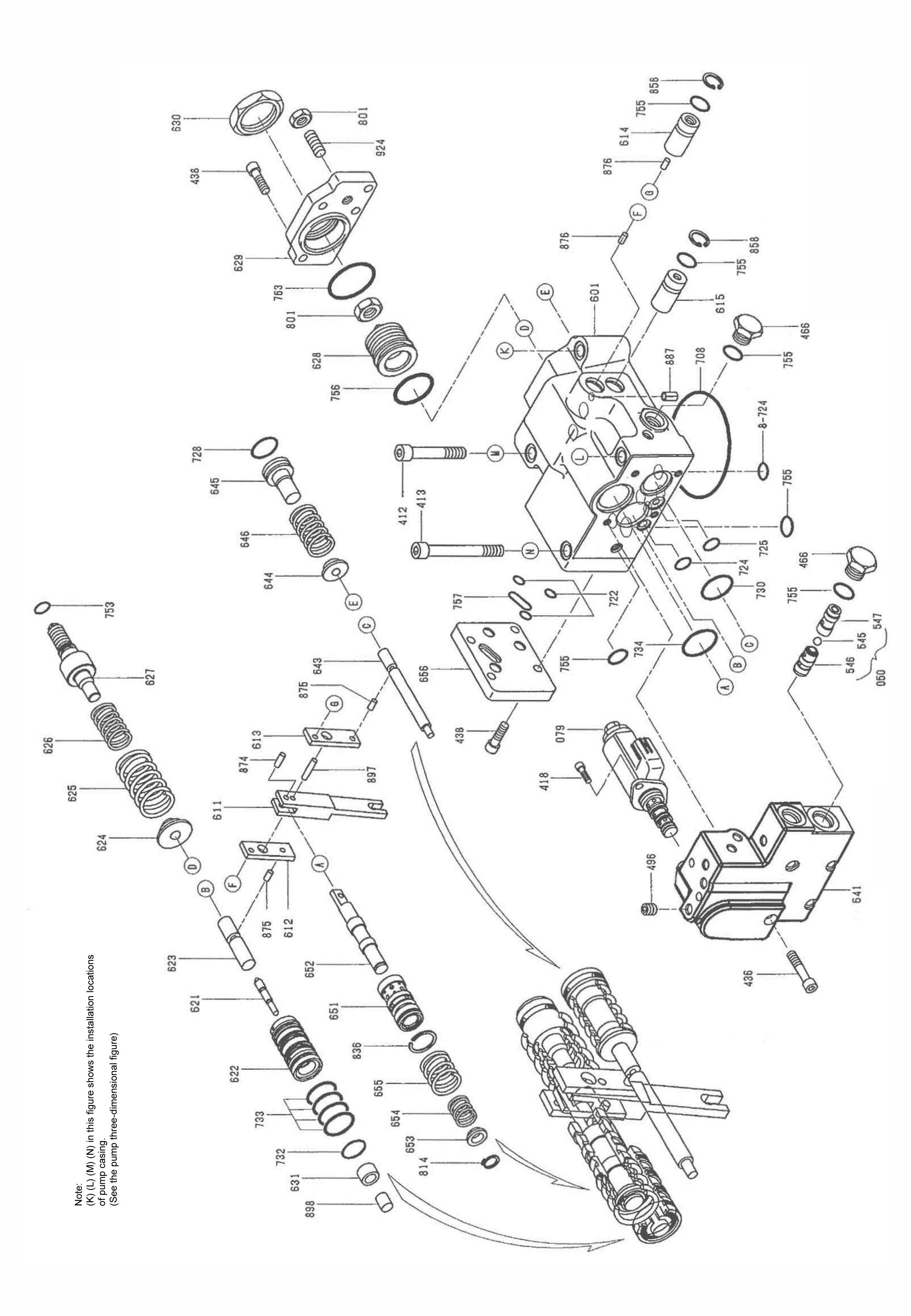
Figure 3. Regulator parts breakdown (KR3G-9X04-HV)
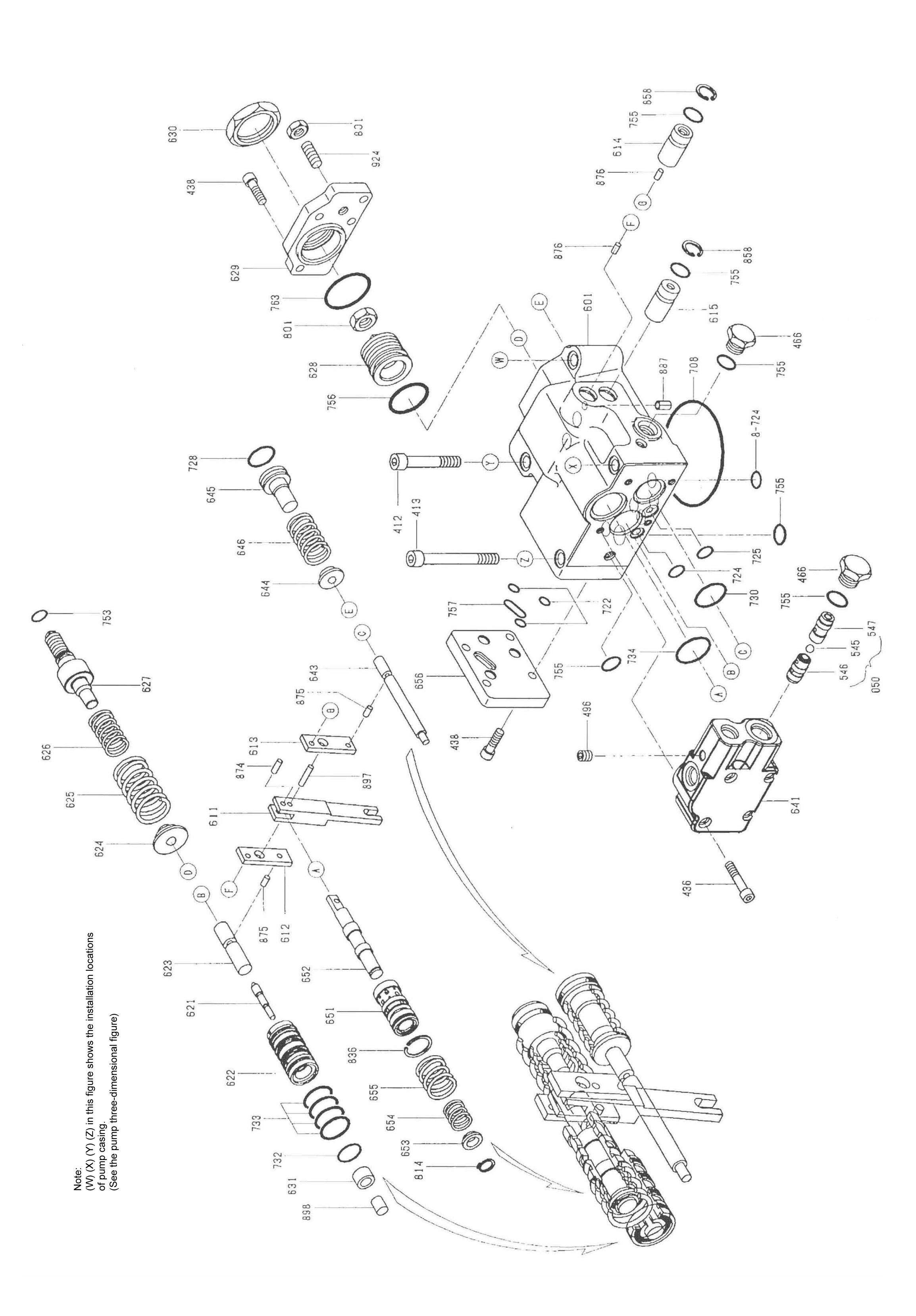
Figure 4. Regulator parts breakdown (KR3G-9Y04-HV)