3 minute read
ELECTRICAL EQUIPMENT


1. STARTER CABLE Type With Power Tilt
a. REMOVAL
1) Remove the following:
- engine cover (P. 5-1).
- left engine under cover (P. 5-3).
2) Unfasten the wire band, and remove the power tilt relay wire connectors with the connector holder attached from the starter case B.
3) Disconnect the 1P connector and remove the connector from the connector holder.
4) Remove the fuse holder from the fuse holder bracket.
5) Pull the starter cable connectors from the holder on the starter case B, and disconnect the white and white/black wire connectors..
6) Open the four wire band clips and remove the spiral pro-
7) Open the wire band on the starter magnetic switch.
8) Remove the 6 mm self-locking nut and disconnect the
9) Remove the 6 x 12 mm flange bolt and disconnect the tectors. starter cable from the starter magnetic switch. battery ground terminal.
[l] 6 mm SELF-LOCKING NUT
[2] WIRE BAND CLIP (4)
171
161
10)Remove the 6 x 14 mm flange bolt and starter cable
11) Open the wire band and remove the starter cable. bracket.
6 x 14 9 [l] STARTER CABLE BRACKET
b. INSTALLATION
1) Install the oil case grommet to the starter cable and align the inside of the grommet with the white tape on the starter cable, and install them onto the oil case.
2) Secure the starter cable with the wire band clip and install the starter cable bracket by aligning the cutout with the boss on the oil case and tighten the 6 x 14 mm flange bolt securely.
3) Route the starter cable.
4) Tighten the ground terminal to the cylinder block using the 6 x 12 mm flange bolt.
5) Connect the starter cable to the starter magnetic switch and adjust the terminal direction so that the starter cable contacts to the clamp bracket on the starter magnetic switch body as shown.
6) Tighten the self-locking nut t the specified torque.
TORQUE: 5.5 N-m (0.55 kgfAm, 4.0 IbfAft)
7) Secure the starter cable and control box wire harness (Remote control type only) with the cable band on the starter magnetic switch.
121
6 mm SELF-LOCKING NUT
5.5 N rn (0.55 kgf rn, 4.0Ibf ft)
8) Connect the white wire connectors and set them in the connector holder on the starter case B.
See page 2-14 and 2-15.
9) Install the power tilt relay wire connectors with the con- nector holder on the starter case B.
10)Set the fuse holder to the fuse holder bracket.
11)Route the charge wire (fuse line) along the main wire harness as shown and wrap the wires with the spiral protectors. Secure the them with the wire band clips.
12)Reinstall the removed parts in the reverse order of removal.
11 1
WIRE BAND CLIP (4) r11-1
Replace the wire band with new one, if it has been cut.
After securing the wires with a new wire band, cut the end of the wire band as projected length is about 15 mm (0.6 in).
15 mm (0.6in) r41 SPIRAL PROTECTOR
Wrap the wires with the spiral protector starting from the branch Doint of the main harness.
141-1
MAIN WIRE HARNESS
131 SPIRAL PROTECTOR (UPPER)
The starting point of winding must be 5 - 20 mm (0.2 - 0.8 in) away from the lower spiral protector.
SPIRAL PROTECTOR
2. POWER TILT RELAY I
a. REMOVAL
1) Remove the following: - engine cover (P. 5-1 of the base shop manual).
2) Open the wire band and free the wires.
3) Remove the wires from the wire clip on the connector holder. Pull the connector holder from the starter case B with the mounting rubbers attached.
4) Disconnect the power tilt relay 2P and 1P connectors.
5) Disconnect the power tilt relay connectors from the power tilt switch wire (Tiller handle type) or main wire harness (Remote control type).
6) Remove the 6 x 12 mm flange bolt and disconnect the
7) Remove the power tilt relay.
8) Remove the 6 x 14 mm flange bolts and power tilt relay power tilt relay ground terminal from the engine. bracket.
b. INSPECTION
Check for continuity between the terminals:
Connect the battery to the Light blue (+) and Black (-) terminals. There should be continuity between the White and Blue terminals.
Connect the battery to the Light green (+) and Black (-) terminals. There should be continuity between the White and Green terminals
c. INSTALLATION
1) Install the relay bracket with the 6 x 12 mm flange bolts.
2) Install the power tilt relay to the mount rubber and install
3) Adjust the relay ground terminal direction and tighten the them to the relay bracket. 6 x 12 mm flange bolt securely.
1
4) Route the power tilt relay wires and connect the connec- tors. mounting rubbers.
5) Install the connector holder to the starter case B with the
6) Clamp the wires with the wire clips.
7) Secure the wire with the wire band.
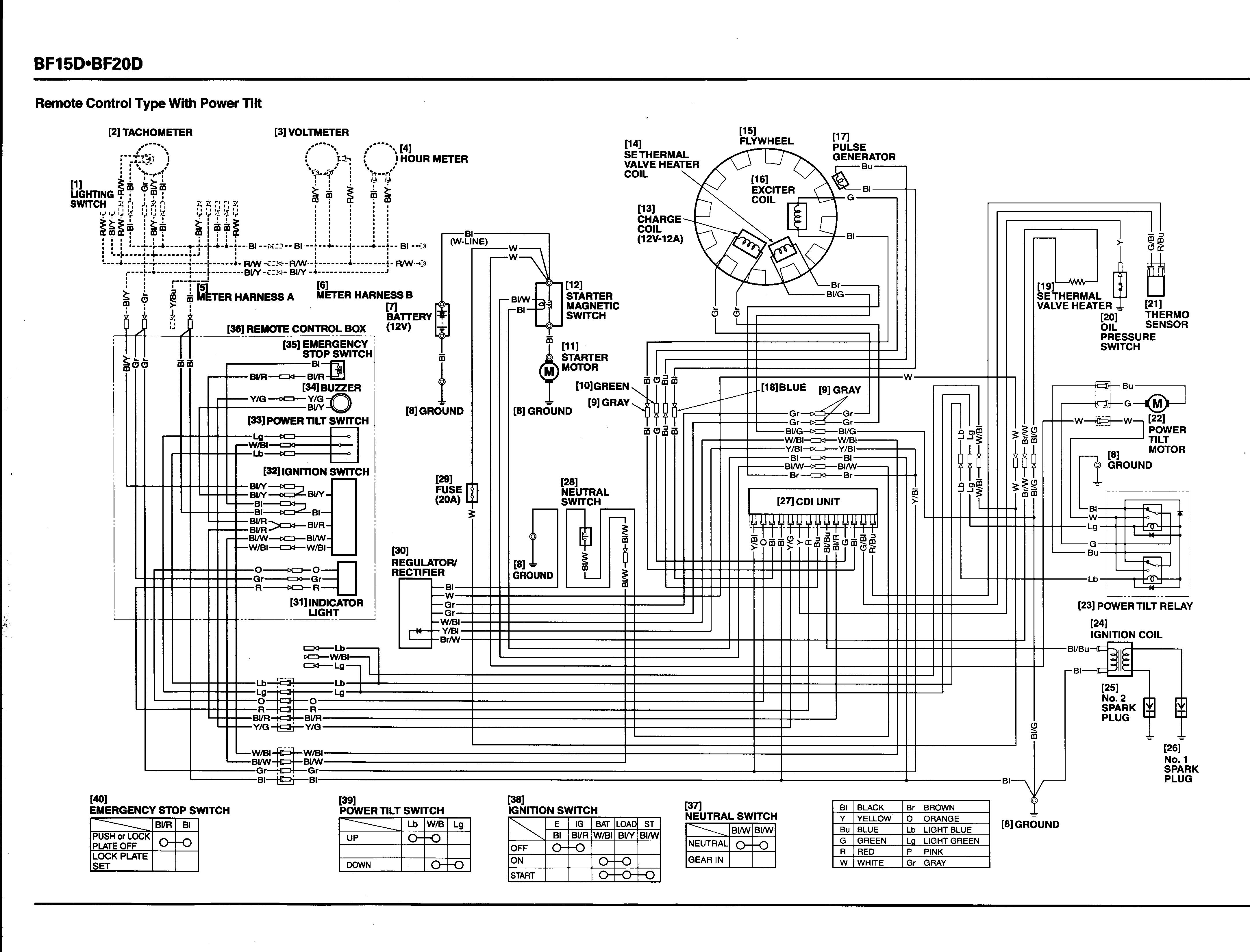
Remote Control Type With Power Tilt