4 minute read
Steel Tank


SCREW (4) /
REASSEMBLY: Check the float for smooth movement.
[6] TUBE CLIP B,.1D I
Clean any dirt or foreign material from the fuel tank strainer, and check for J tears in the strainer mesh. ._
[12] INLET VALVE
[13]FUEL HOSE (SHORT)
REASSEMBLY: Check for cracks and deteriorations. Replace if necessary.
[14]TANK CAP
[15]FUEL TANK
CAPACITY:
13 !2 (3.4 US gal, 2.9 Imp gal)
ASSEMBLY: Clean the tank of dirt or dust accumulation, before assembly.
Primer Valve Assembly
1) Install the inlet valve (has the pin) at the side marked with " I)" on the priming bulb.
2) Install the outlet valve (has the valve seat) at the other side.
Do not confuse the inlet valve and the outlet valve. Install the priming bulb with the "I) " mark toward the motor side.
I
1. NEUTRAL START CABLE
2. RECOIL STARTER
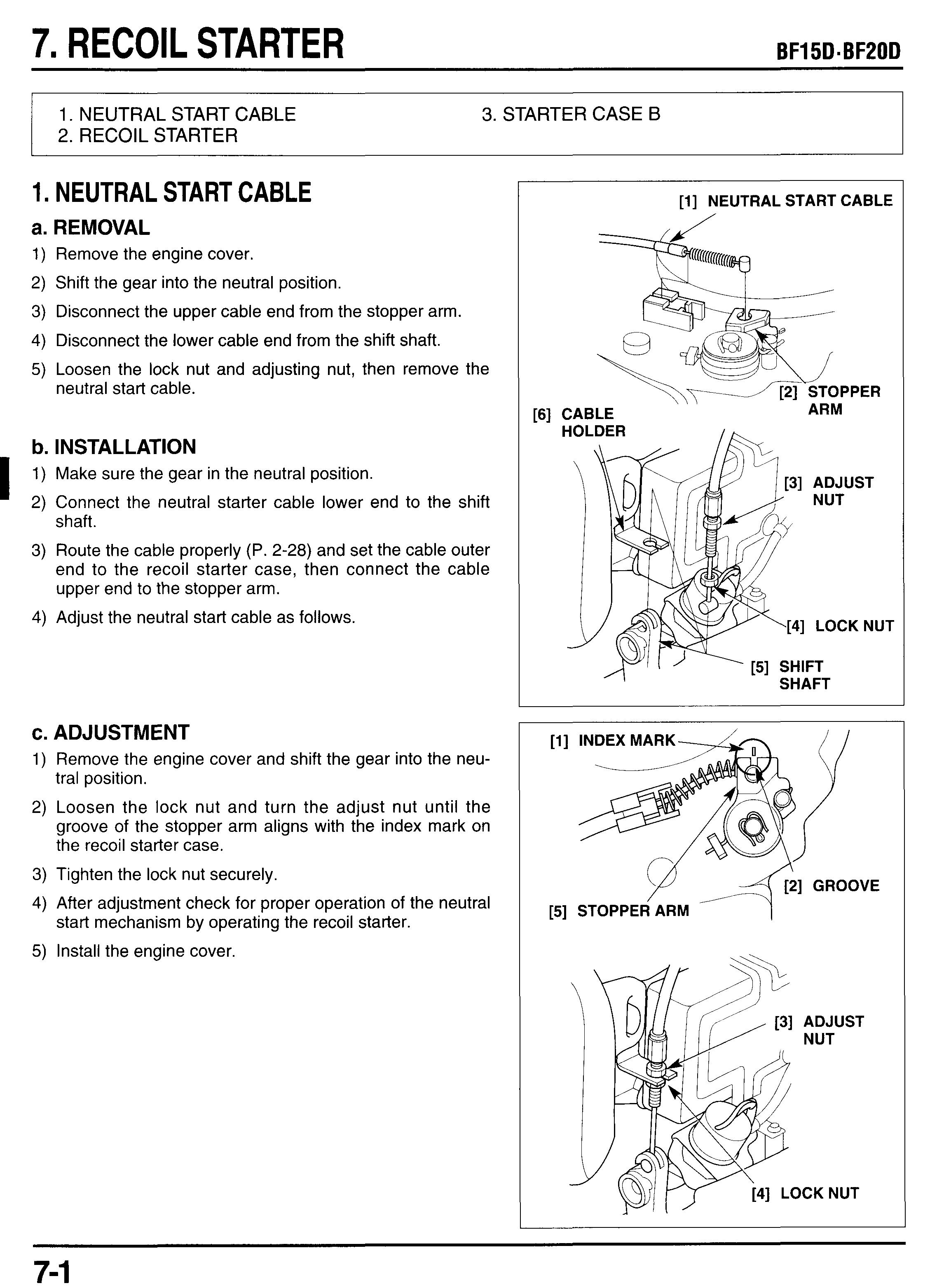
1. NEUTRAL START CABLE
a. REMOVAL
1) Remove the engine cover.
2) Shift the gear into the neutral position.
3) Disconnect the upper cable end from the stopper arm.
4) Disconnect the lower cable end from the shift shaft.
3. STARTER CASE B
5) Loosen the lock nut and adjusting nut, then remove the neutral start cable.
b. INSTALLATION
1) Make sure the gear in the neutral position.
2) Connect the neutral starter cable lower end to the shift shaft.
3) Route the cable properly (P. 2-28) and set the cable outer end to the recoil starter case, then connect the cable upper end to the stopper arm.
4) Adjust the neutral start cable as follows.
c. ADJUSTMENT
1) Remove the engine cover and shift the gear into the neutral position.
2) Loosen the lock nut and turn the adjust nut until the groove of the stopper arm aligns with the index mark on the recoil starter case.
3) Tighten the lock nut securely.
4) After adjustment check for proper operation of the neutral
5) Install the engine cover. start mechanism by operating the recoil starter.
2. RECOIL STARTER
a. REMOVAL
1) Remove the engine cover.
2) Disconnect the neutral start cable from the stopper arm.
3) Pull out the neutral start cable from the recoil starter
4) Remove the three 6 x 22 mm flange bolts and recoil case. starter assembly.
[l] NEUTRAL START CABLE
[l] NEUTRAL START CABLE
,PI RECOIL STARTER ASSEMBLY
b. DISASSEMBLY
Wear gloves and eye protection. During disassembly, take care not to allow the return spring to come out.
1) Remove the cotter pin and washer, and discard the cotter pin. Replace with new one when reassembly.
2) Unhook the stopper spring from the reel stopper.
3) Remove the stopper arm, stopper spring and reel stopper.
4) Remove the 6 x 14 mm washer bolt, set plate, collar and rope guide roller.
5) Hold the starter rope.
6) Remove the grip plug and pull out the starter rope end from the start grip. Untie the rope end and remove the starter grip.
7) Pull out the starter rope from the starter case holding the starter reel to prevent from turning the reel.
8) Align the starter rope with the cutout of the starter reel. Hold the starter rope end and slowly turn the reel clockwise to release the spring preload.
9) Remove the 6 x 20 mm washer bolt and friction plate and friction spring.
10)Remove the recoil starter reel from the starter case taking care not to allow the starter spring to come out.
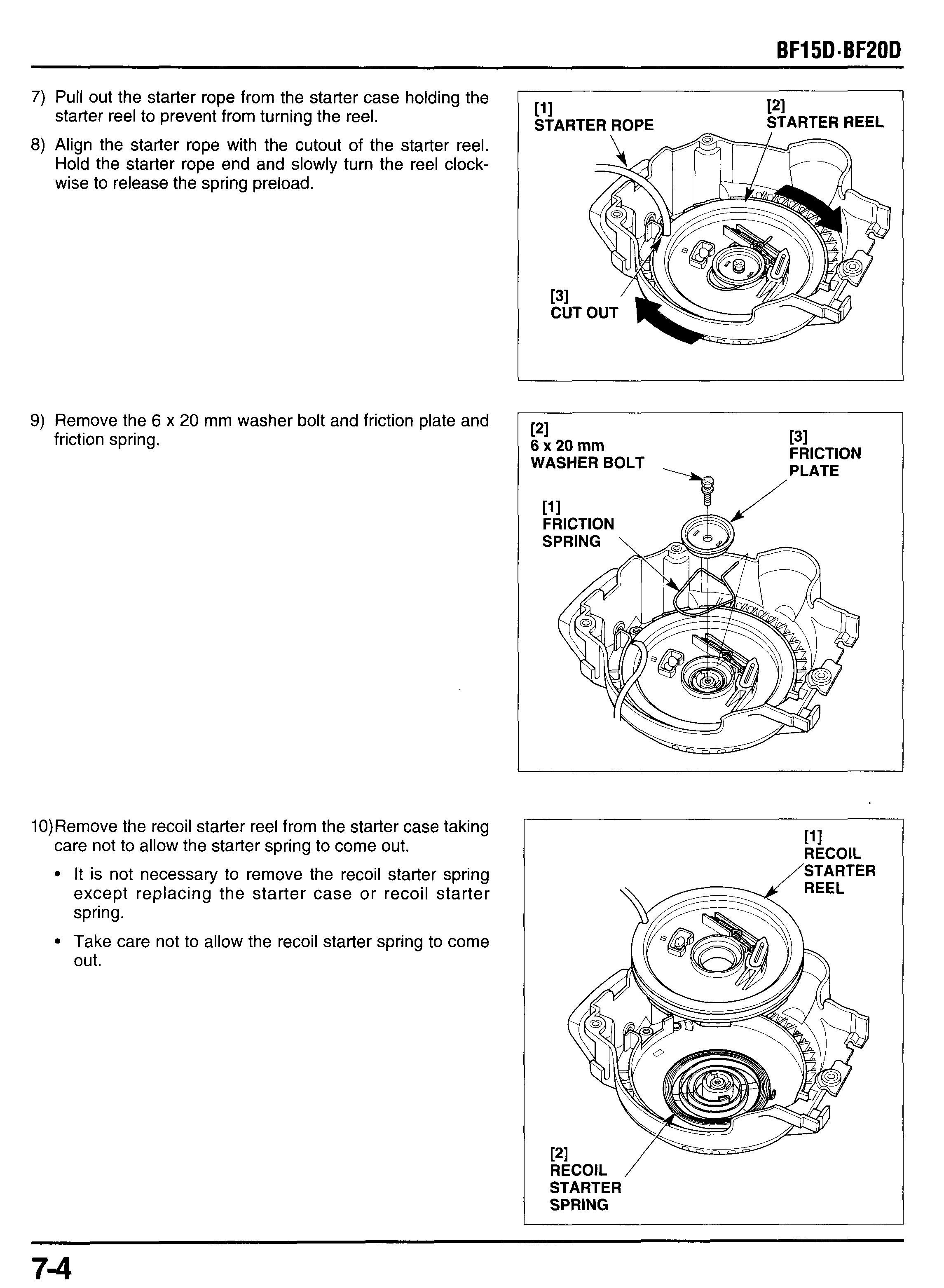
It is not necessary to remove the recoil starter spring except replacing the starter case or recoil starter spring.
Take care not to allow the recoil starter spring to come out.
11)Pry off the E-clip from the starter ratchet behind the starter reel. return spring. starter rope if replacement is necessary.
12)Remove the starter ratchet, ratchet guide and ratchet
Assembly
PI RETURN SPRING 111 6 x 20 mm WASHER BOLT 131 5.5 N*m (0.55 kgfm, 4.0Ibf*ft) RATCHET I I PI ,STARTER
FRICTION SPRING I /
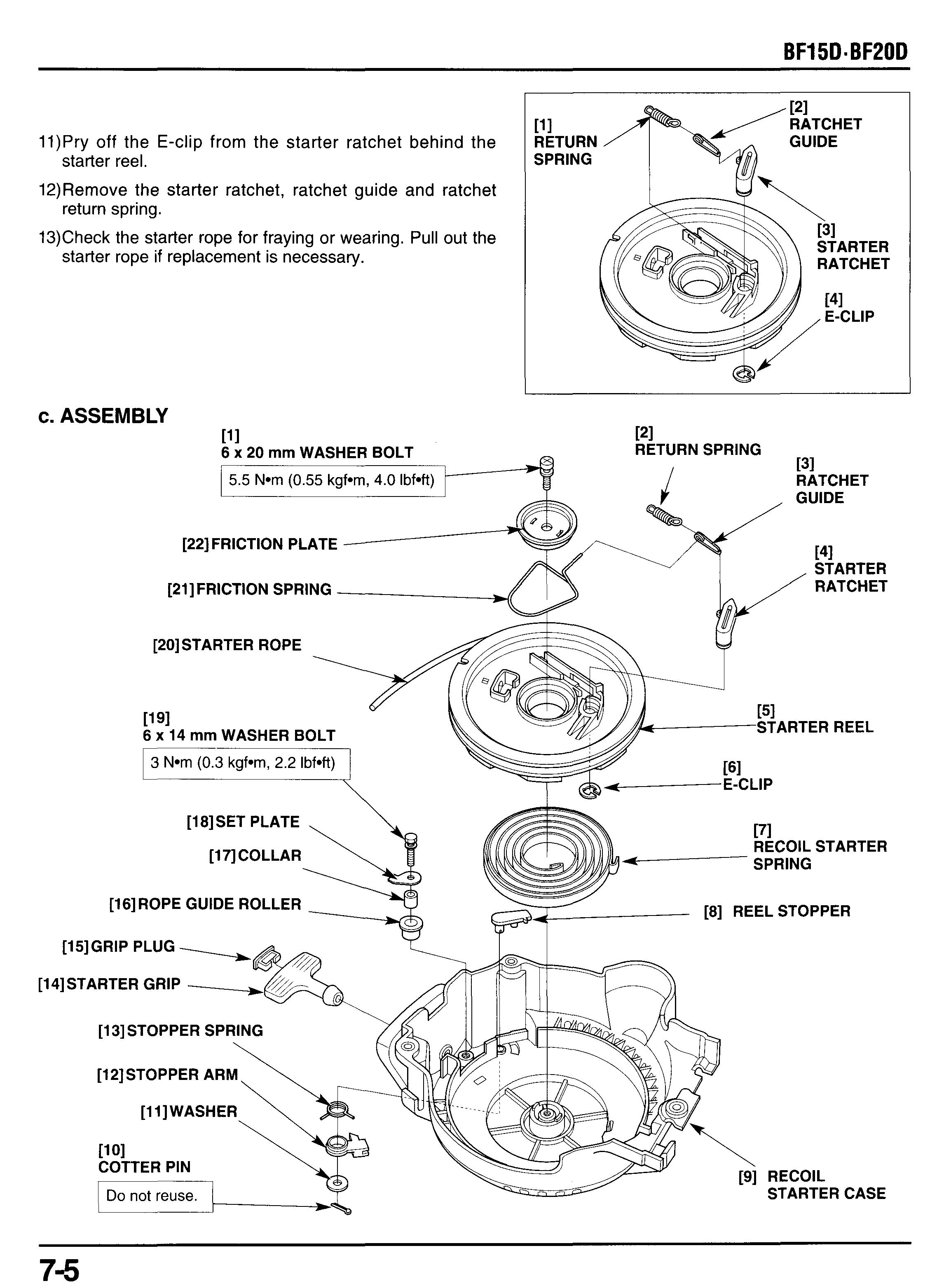
RATCHET x 14 mm WASHER BOLT
REEL STOPPER
[14]STARTER GRIP
[13]STOPPER SPRING
COTTER
PIN
1) Install the return spring, ratchet guide and starter ratchet, and set the E-clip
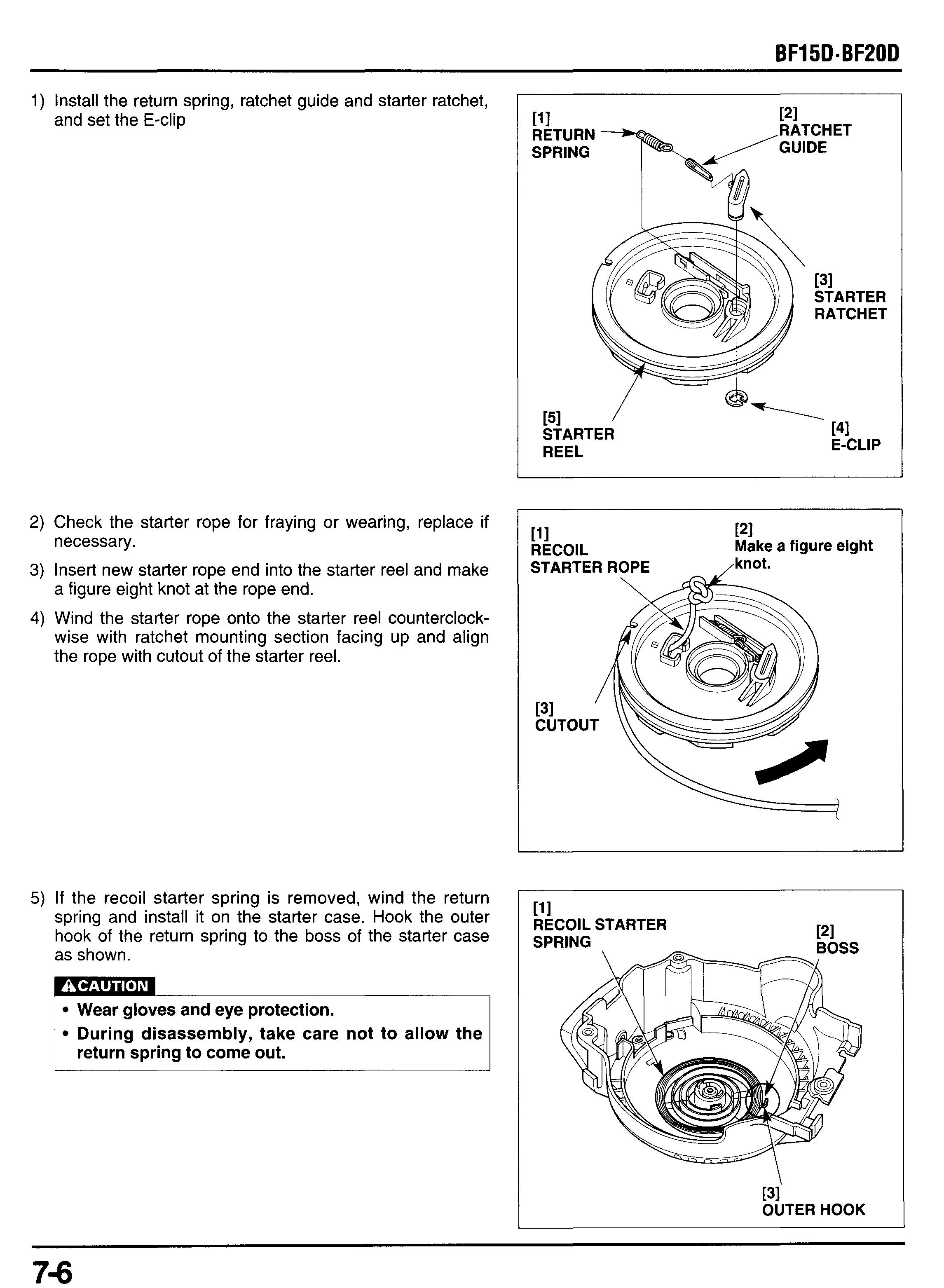
2) Check the starter rope for fraying or wearing, replace if necessary.
3) Insert new starter rope end into the starter reel and make a figure eight knot at the rope end.
4) Wind the starter rope onto the starter reel counterclockwise with ratchet mounting section facing up and align the rope with cutout of the starter reel.
5) If the recoil starter spring is removed, wind the return spring and install it on the starter case. Hook the outer hook of the return spring to the boss of the starter case as shown.
151 STARTER REEL 111 RECOIL PI Make a figure eight STARTER ROPE ,knot. 111 RECOIL STARTER
During disassembly, take care not to allow the return spring to come out.
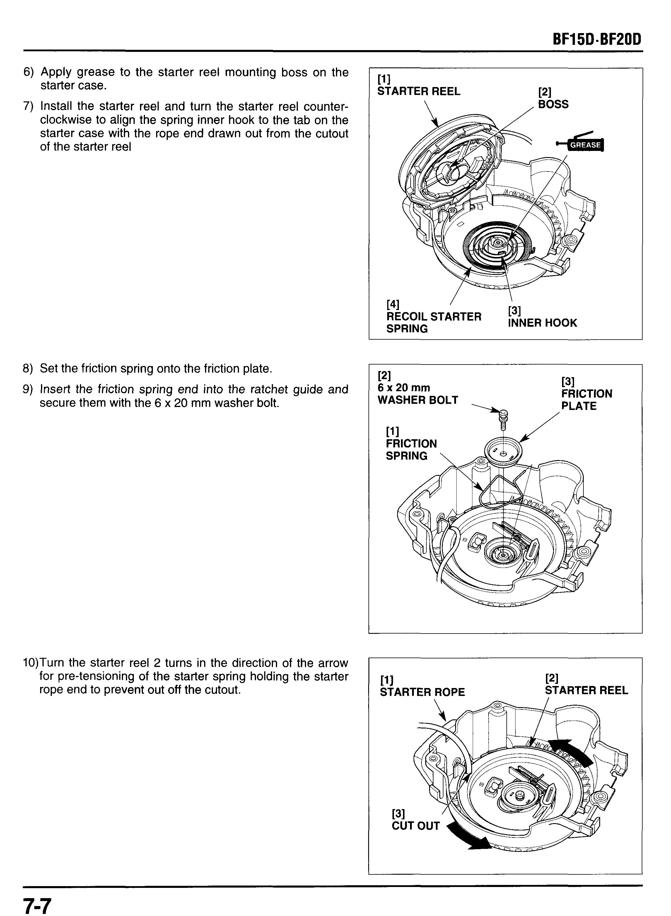
6) Apply grease to the starter reel mounting boss on the starter case.
7) Install the starter reel and turn the starter reel counterclockwise to align the spring inner hook to the tab on the starter case with the rope end drawn out from the cutout of the starter reel
8) Set the friction spring onto the friction plate.
9) Insert the friction spring end into the ratchet guide and secure them with the 6 x 20 mm washer bolt.
10)Turn the starter reel 2 turns in the direction of the arrow for pre-tensioning of the starter spring holding the starter rope end to prevent out off the cutout.
11)Pull out the rope end from the starter case hole holding the starter reel not to turn and hold the starter rope.
12)lnstall the starter grip, and make a figure eight knot. Pull the starter rope into the starter grip and install the grip Plug.
13)Apply grease to the outside of the collar.
14)lnstall the rope guide roller, collar and set plate, and tighten the 6 x 14 mm washer bolt securely.
15)Check the operation of starter assembly by pulling the starter rope several times.
16)lns all the reel stopper and E spring as shown. 3pper spring, and set the
17)lnstall the stopper arm and washer, then secure them using a new cotter pin.
d. INSTALLATION
1) Install the recoil starter assembly by aligning the recoil starter case and starter case B as shown.
2) Tighten the 6 X 22 mm flange bolt securely.
3) Connect the neutral start cable to the stopper arm.
4) Adjust the neutral start cable (P. 7-1).
5) Install the engine cover.
3. STARTER CASE B
a. REMOVAL
1) Remove the following pars:
- engine cover (P. 5-1).
- Left engine under cover (P. 5-2).
- right engine under cover (P. 5-3).
- recoil starter (P. 7-2).
2) Pull out the connectors and wires from the holder on the starter case B
3) Pull off the breather tube from the clamp on the starter case B and remove it. Disconnect the breather tube from the cylinder head cover.
4) Remove the starter case B with the drain tube attached by disconnecting the drain tubes from the lower setting holes.
b. INSTALLATION
Installation is the reverse order of removal. See page 2-36 for wires and connectors clamping.


