7 minute read
14. STEERING RODlREMOTE CONTROL BOX


1. STEERING ROD
2. REMOTE CONTROL CABLE
1. STEERING ROD a. DISASSEMBLY/REASSEMBLY
3. CONTROL BOX WIRE HARNESS
4. REMOTE CONTROL BOX
111 STEERING CABLE
151 3/8-24 UNF
151 TILTING BOLT CAP
161 3/8-24 UNF SELF-LOCKING NUT
2. REMOTE CONTROL CABLES
a. REMOVAUINSTALLATION
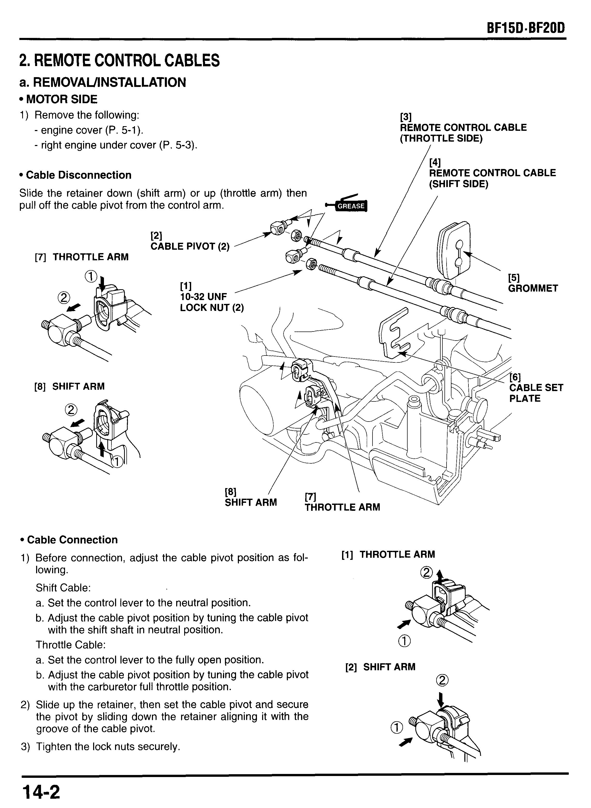
MOTOR SIDE
1) Remove the following:
- engine cover (P. 5-1).
- right engine under cover (P. 5-3).
Cable Disconnection
Slide the retainer down (shift arm) or up (throttle arm) then pull off the cable pivot from the control arm.
[31 REMOTE CONTROL CABLE (THROTTLE SIDE) I /
Cable Connection
1) Before connection, adjust the cable pivot position as fol- lowing.
Shift Cable: a. Set the control lever to the neutral position. b. Adjust the cable pivot position by tuning the cable pivot with the shift shaft in neutral position.
Throttle Cable: a. Set the control lever to the fully open position. b. Adjust the cable pivot position by tuning the cable pivot with the carburetor full throttle position.
2) Slide up the retainer, then set the cable pivot and secure the pivot by sliding down the retainer aligning it with the groove of the cable pivot.
3) Tighten the lock nuts securely.
Control Box Side
Screw the lock nut and eye end more than 8 mm (0.3 in) onto the threads of the remote control cable and tighten the lock nut securely.
Apply grease to the pin of the control arm before connecting the cable.
After installation, adjust the cables and connect to the motor (P. 14-2).
REMOTE CONTROL CABLE
3. CONTROL BOX WIRE HARNESS
a. REMOVAUl NSTALLATI0N
1) Remove the engine cover.
121 6P CONNECTOR
RE BAND CLIP
Align the wire tie of the control box wire harness with the oil case grommet and clamp the wire harness securely.
I 161 STARTER CABLE PLATE
ASSEMBLY:
Align the cutout with the pin on the oil case.
I [6]-1 CUTOUT I [6]-1 PIN
151 [31 WIRE BAND CLIP
/ BATTERY CABLE
ASSEMBLY:
Align the white tape of the battery cable with the oil case grommet.
OIL CASE GROMMET [514
151-2 WHITE TAPE
4. REMOTE CONTROL BOX
a. DISASSEMBLY COVERS AND CABLES
1) Remove the two 5 x 25 mm self-tapping screws and control box cover.
2) Remove the 6 mm lock pins and washers and disconnect the control cables, two 6 mm washers and cable clamp spacer.
3) Remove the 5 x 12 mm oval screws and fast idle lever.
4) Remove the five 5 x 25 mm self-tapping screws and control box cover B.
6 mm LOCK PIN (2)
[71
181 5 x 25 mm SELF-TAPPING SCREW(2)
5xl2mm / OVAL SCREW 12)
121 FAST IDLE LEVER
5x25mm 111 +ND 12)
SELF-TAPPING --SCREW(5)
[111 REMOTE CONTROL CABLE (SHIFT SIDE)
Electrical Equipment
Remove the 22 mm lock nut and ignition switch.
Remove the 16 mm lock nut and emergency stop switch.
Cut the wire band and discard it and disconnect the wire connectors.
When installing, use a new wire band and secure the wire connectors.
Remove the control box wire harness, warning buzzer, ignition switch emergency stop switch and indicator.
161 INDICATOR i INSPECTION: P. 14-1 1 I
[51 CONTROL BOX WIRE HARNESS
[81 WARNING BUZZER
171 INDICATOR BOOT
[11 EMERGENCY STOP SWITCH
INSPECTION: P. 14-11
Sliding Plate
Remove the 4 mm E-clip and 6 mm washer and disconnect the link joint arm from the fast idle wheel.
Remove the fast idle spring.
Remove the 5 x 10 mm screw and 5 mm washer. Remove the fast idle cam and spring.
Remove the 5 x 10 mm self-tapping screw, and remove the spring set ring, 13 x 13 mm fast idle detente roller, fast idle detente spring and 5 mm washer.
Remove the 4 x 10 mm self-tapping screw, 4 mm washer and switch start cam.
Remove the 6 x 6 mm roller.
FAST IDLE CAM
FAST IDLE DETENTE
.7 X 23.9 mm FAST IDLE ETENTE SPRING
SWITCH START CAM
7) Remove the 7 mm E-clip and 8 mm washer and remove
8) Remove the 6 x 10 mm screw and remove the joint link the link joint arm and link joint collars. bracket and sliding plate
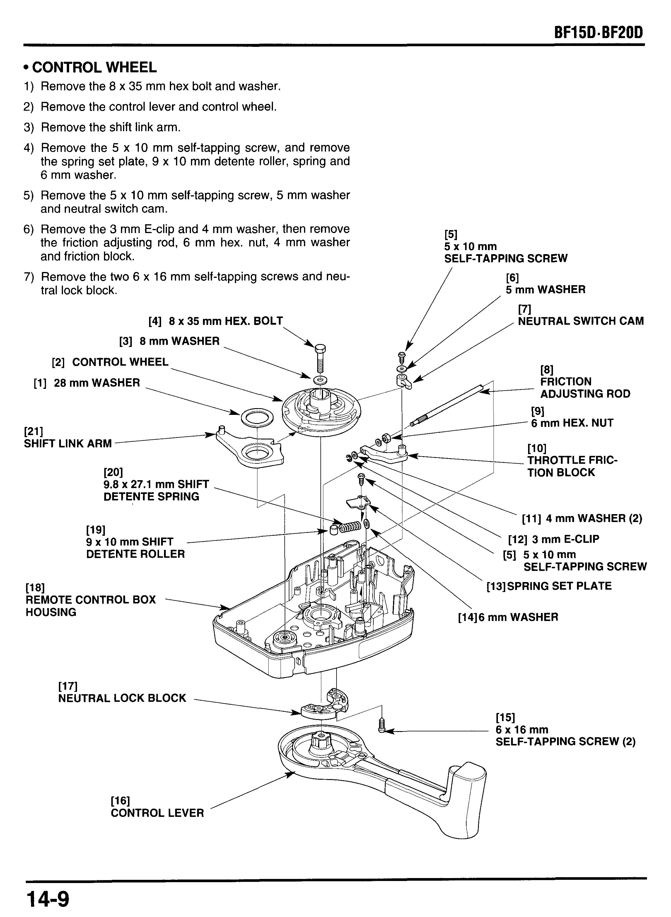
Control Wheel
Remove the 8 x 35 mm hex bolt and washer.
Remove the control lever and control wheel.
Remove the shift link arm.
Remove the 5 x 10 mm self-tapping screw, and remove the spring set plate, 9 x 10 mm detente roller, spring and 6 mm washer.
Remove the 5 x 10 mm self-tapping screw, 5 mm washer and neutral switch cam.
Remove the 3 mm E-clip and 4 mm washer, then remove the friction adjusting rod, 6 mm hex. nut, 4 mm washer
151 5xlOmm and friction block. SELF-TAPPING SCREW
Remove the two 6 x 16 mm self-tapping screws and neutral lock block.
[3] 8 mm WASHER
[4] 8 x 35 mm HEX. BOLT .
[2] CONTROL WHEEL
[l] 28 mm WASHER
1211
SHIFT LINK ARM
9.8 x 27.1 mm SHIFT DETENTE SPRING
5 mm WASHER
[71
NEUTRAL SWITCH CAM
ADJUSTING ROD
6 mm HEX. NUT
THROTTLE FRIC-
[ll] 4 mm WASHER (2)
[12] 3 mm E-CLIP 9 x 10 mm SHIFT DETENTE ROLLER
SELF-TAPPING SCREW
1181 REMOTE CONTROL BOX HOUSING 1171
NEUTRAL LOCK BLOCK --
[13]SPRING SET PLATE
SELF-TAPPING SCREW (2)
Control Lever
1) Remove the 5 x 10 mm screw, lever set plate and neutral
2) Remove the 5 x 12 mm self-tapping screw and control release lever and lever spring. lever grip.
c. INSPECTION IGNITION SWITCH
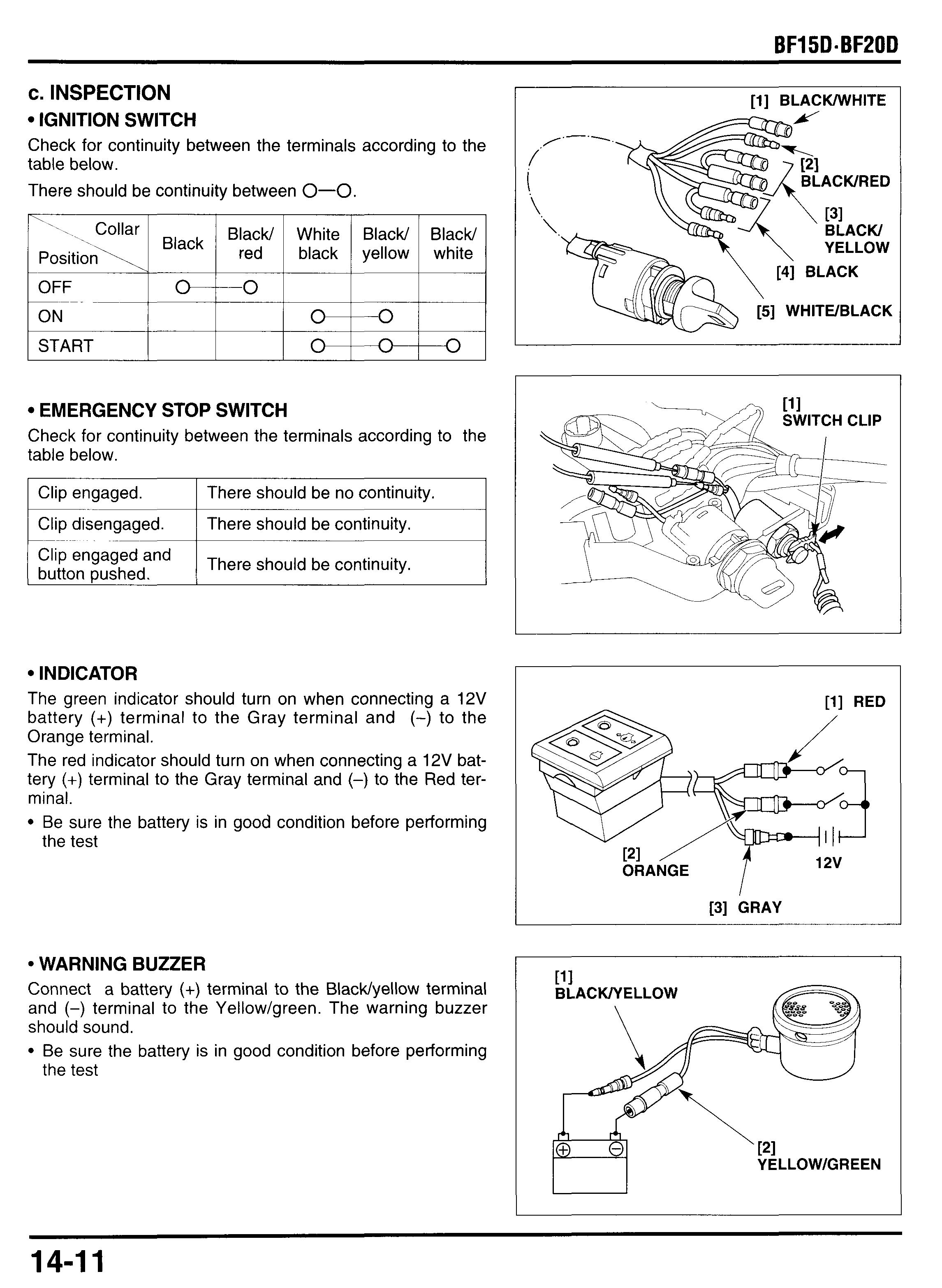
Check for continuity between the terminals according to the table below.
Emergency Stop Switch
Check for continuity between the terminals according to the table below.
I Clip engaged. I There should be no continuity. I
‘lip engaged and
There should be continuity. button pushed.
Indicat0 R
The green indicator should turn on when connecting a 12V battery (+) terminal to the Gray terminal and (-) to the Orange terminal.
The red indicator should turn on when connecting a 12V battery (+) terminal to the Gray terminal and (-) to the Red terminal.
Be sure the battery is in good condition before performing the test
Warning Buzzer
Connect a battery (+) terminal to the BlacWyellow terminal and (-) terminal to the Yellow/green. The warning buzzer should sound.
Be sure the battery is in good condition before performing the test
d. ASSEMBLY
1) Install the lever grip and secure it with the 5 x 12 mm selftapping screw.
2) Install the lever spring, neutral release lever and lever set plate, tighten the 5 x 10 mm self-tapping screw.
3) Install the neutral lock block as shown and secure it with the 6 x 16 mm self-tapping screws.
4) Apply marine grease to the detente spring (9.8 x 27.1 mm) and detente roller (9 x 10 mm). Install the 5 mm washer, spring and detente roller. set the spring set plate by aligning the hole of the set plate with the boss of the control box housing, and tighten the 5 x 10 mm self-tapping screw.
5) Apply marine grease to the friction block pivot point. Set the 6 mm hex. nut in the control box housing, and thread the adjusting rod slightly. Install the 4 mm washer to the adjusting rod, then install the throttle friction block and 4 mm washer and secure the 3 mm E-clip.
6) Install the neutral switch cam and 5 mm washer and secure the 5 x 10 mm self- tapping screw.
7) Apply marine grease to the sliding surfaces of the shift link arm, 28 mm washer, control wheel and control lever, then install them to the control box housing.
8) Install the 8 mm washer and tighten the 8 x 35 mm hex bolt to the specified torque.
TORQUE: 20 N*m (2.0 kgf*m, 14 Ibfaft)
9) Install the link joint bracket by aligning the hole of the link joint bracket with the boss on the control box housing. Tighten the 6 x 10 mm screw.
10)Attach the sliding plate collar to the sliding plate with its opening toward the opposite side of the UP mark and shorter lip facing down as shown.
11)Apply marine grease to the sliding surfaces of the sliding plate and control wheel, and install the sliding plate with the UP mark facing up.
12)lnstall the link joint arm and joint collars to the sliding plate, then install them onto the control wheel and secure them with the 8 mm washer and 7 mm E-clip.
13)Apply marine grease to the detente spring (12.7 x 23.9 mm) and detente roller (13 x 13 mm). Install the 5 mm washer, spring and detente roller. set the spring set plate by aligning the hole of the set plate with the boss of the control box housing, and tighten the 5 x 10 mm self-tapping screw.
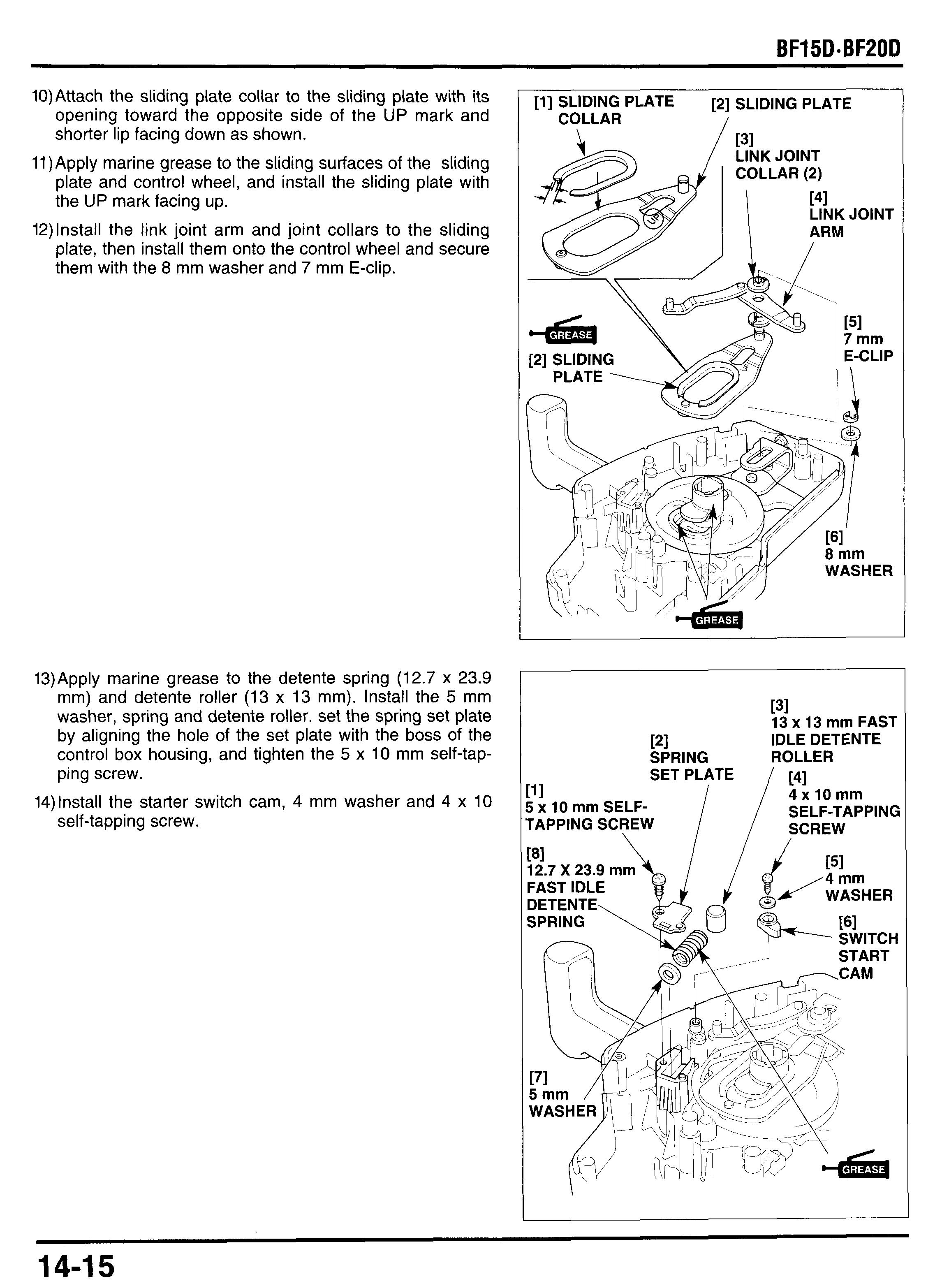
14)lnstall the starter switch cam, 4 mm washer and 4 x 10 self-tapping screw.
131
111 SETPTE ,,/1 4xlOmm
13 x 13 mm FAST IDLE DETENTE ROLLER 121 SPRING
5 x 10 mm SELF- SELF-TAPPING SCREW TAPPING SCREW \
15)Apply marine grease to the 6 x 6 mm roller and install it in the concave of the control wheel as shown.
16)Apply marine grease to the sliding surfaces of the fast idle cam. Set the fast idle spring to the fast idle cam and install them onto the idle cam pivot shaft by pushing the detente roller slightly. Install the 5 mm washer and tighten the 5 x 10 mm screw.
17) Install the 6 mm washer and secure the 4 mm E-clip.
18)lnstall the control box wire harness and indicator and then connect the connectors.
19)lnstall the emergency stop switch and ignition switch and tighten the lock nuts to the specified torque. Install the ignition switch with the flat of the flange facing down as shown.
TORQUES:
16 mm Lock nut: 1.5 N*m (0.15 kgf*m, 1.1 Ibf*ft)
22 mm Lock nut: 4.8 N *m (0.49 kgf Om, 3.5 Ibf Oft)
20)Install the warning buzzer. Connect the connectors and clamp the connectors with the wire band and set the wires in the control box housing as shown.
2l)lnstall the control box cover B and tighten the 5 x 25 mm self-tapping screws.
22)lnstall the fast idle lever and tighten the 5 x 12 mm oval screws.
23)Connect the control cables (see page 14-3) and install the control box cover C and tighten the 5 x 25 mm selftapping screws.
[I1
5 x 25 mm SELF-TAPPING SCREW(5)
2 N.m (0.2 kgf.m, 1.4 Ibf.ft)
[31
5xl2mm OVAL SCREW(2) 171 / CONTROL BOX COVER C
181 5 x 25 mm SELF-TAPPING SCREW(5)
REMOTE CONTROL CABLE (SHIFT SIDE)


