3 minute read
k


15)Turn the tilt shaft until the locking tab faces toward up, and align the pin holes of the tilt shaft bracket with pin hole of tilt shaft and set a new 3 x 25 mm spring pin.
16)Drive the spring pins using a commercially available pin driver until the both projected distances are equally as shown.
(commercially
17) Install the tilt lever spring with the short end toward the tilt lever bracket.
18)Set the locking tab to the hole on the tilt arm as shown.
19)lnstall new lock washer by aligning the locking tab with
20)Tighten the 6 mm hex. nut securely, then bend the tab to the hole on the tilt arm. lock the nut as shown.
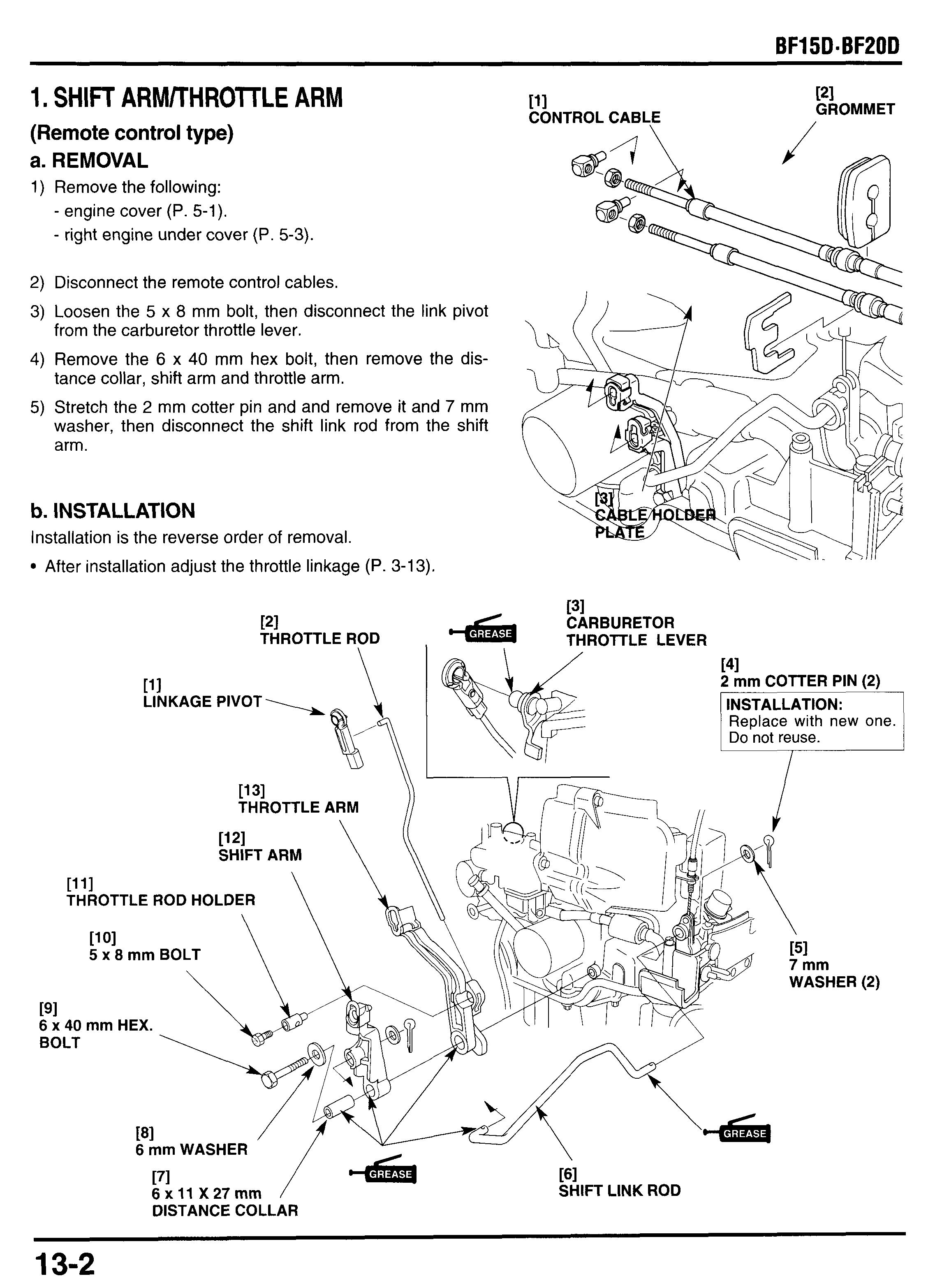
1. SHIFT ARMRHROTLE ARM
(Remote control type) a. REMOVAL
1) Remove the following:
- engine cover (P. 5-1).
- right engine under cover (P. 5-3).
2) Disconnect the remote control cables.
3) Loosen the 5 x 8 mm bolt, then disconnect the link pivot from the carburetor throttle lever.
4) Remove the 6 x 40 mm hex bolt, then remove the distance collar, shift arm and throttle arm.
5) Stretch the 2 mm cotter pin and and remove it and 7 mm washer, then disconnect the shift link rod from the shift arm.
b. INSTALLATION
Installation is the reverse order of removal. After installation adjust the throttle linkage (P. 3-13).
2. SHIFT LEVER (Tiller handle type)
a. REMOVAL
1) Remove the 2 mm cotter pin and 5 mm washer, disengage the link rod from the shift shaft.
Do not reuse the 2 mm cotter pin, replace with new one when reassembly.
2) Remove the shift lever pivot bolt, 10 mm wave washer, two 9 mm plain washers, 6 mm plain washer and shift lever from the tiller handle.
3) Remove the link rod boot, link rod and shift lever.
b. INSTALLATION
1) Apply grease to the link rod end. Connect the link rod to the shift lever.
2) Apply grease to the sliding surface of the pivot bolt. Install the shift lever, 6 mm washer, two 9 mm washers,lO mm wave washer and tighten the pivot bolt.
TORQUE: 12 N*m (1.2 kgf*m, 9 Ibf*ft)
3) Set the link rod boot securely.
4) Connect the link rod to the shift shaft and install the 5 mm washer and a new 2 mm cotter pin. Spread the end of the cotter pin as shown.
ASSEMBLY: Do not reuse. Replace with new one. Spread the end of the cotter pin as shown.
6) Remove the 5 x 12 mm flange bolt, detente spring and spring set plates (remote control type: one plate, tiller handle type: two plate).
7) Remove the four 5 x 12 mm flange bolts and shift shaft plates.
8) Disconnect the shift rod A ,,omthe shift shaft and remove the shift shaft.
SPRING SET PLATE (Remote control type: 1 Tiller handle type: 2)
POI
2 mm COTTER PIN (Remote control type)
191 7 mm WASHER (Remote control type)
SPRING
2 mm COTTER PIN (Tiller handle type)
(Tiller handle type)
171
151
1) Apply grease to the shift shaft;
- link pivot holes.
- detente spring sliding area.
- set plate sliding area.
2) Connect the shift shaft to the shift rod A then set it in the place.
3) Tiller handle type;
Apply grease to the link rod, and connect the link rod to the shift shaft. Install the 5 mm washer and a new 2 mm cotter pin, spread the end of the cotter pin as shown.
Remote control type;
Apply grease to the link rod, and connect the link rod to the shift shaft. Install the 7 mm washer and a new 2 mm cotter pin, spread the end of the cotter pin as shown.
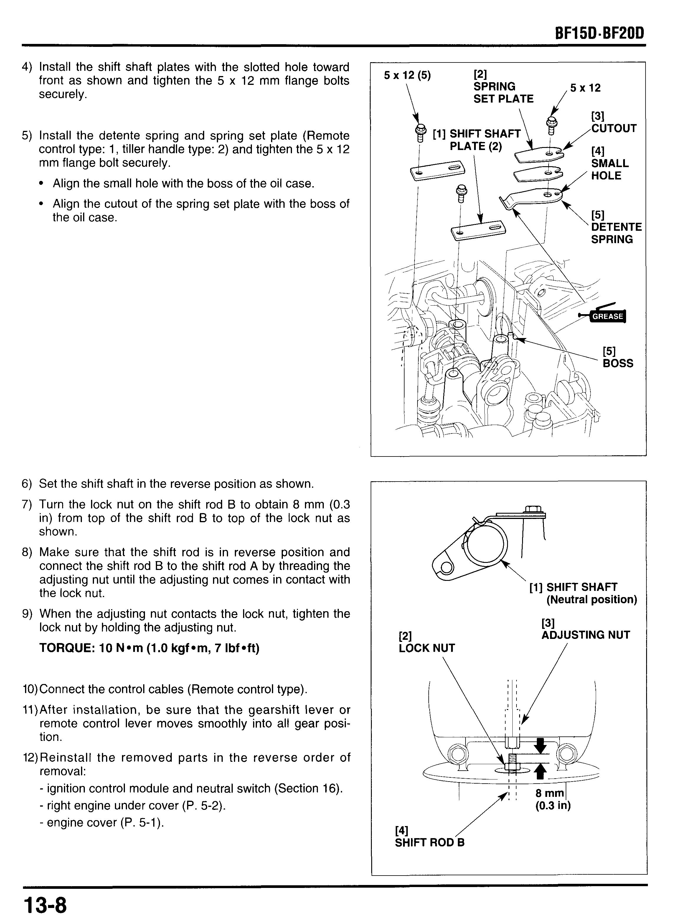
4) Install the shift shaft plates with the slotted hole toward front as shown and tighten the 5 x 12 mm flange bolts securely.
5) Install the detente spring and spring set plate (Remote control type: 1, tiller handle type: 2) and tighten the 5 x 12 mm flange bolt securely.
Align the small hole with the boss of the oil case.
Align the cutout of the spring set plate with the boss of the oil case.
6) Set the shift shaft in the reverse position as shown.
7) Turn the lock nut on the shift rod B to obtain 8 mm (0.3 in) from top of the shift rod B to top of the lock nut as shown.
8) Make sure that the shift rod is in reverse position and connect the shift rod B to the shift rod A by threading the adjusting nut until the adjusting nut comes in contact with the lock nut.
9) When the adjusting nut contacts the lock nut, tighten the lock nut by holding the adjusting nut.
TORQUE: 10 Nom (1.0 kgfom, 7 Ibfoft)
10)Connect the control cables (Remote control type).
11)After installation, be sure that the gearshift lever or remote control lever moves smoothly into all gear position.
12)Reinstall the removed parts in the reverse order of removal:
- ignition control module and neutral switch (Section 16).
- right engine under cover (P. 5-2).
- engine cover (P. 5-1).