6 minute read
OIL CASUSTERN BRACKETlSWlVEL CASE


1. OIL CASE
a. DISASSEMBLY
1) Remove the engine (section 8) then, remove the following:
- propeller and gear case (P. 4-9).
- extension case and tower mount rubber (P. 4-26).
- remote control cable (P. 14-2).
- tiller handle (P. 15-2).
- shift linkage (P. 13-2).
2) Remove the shift rod A, adjusting nut and oil case grom-
3) Remove the two 10 x 25 mm flange bolts and remove the met oil case.
4)
Remove the four 6 x 12 mm flange bolts and remove the upper mount rubber and set plates. Check the upper mount rubber for damage or deterioration, replace if necessary.
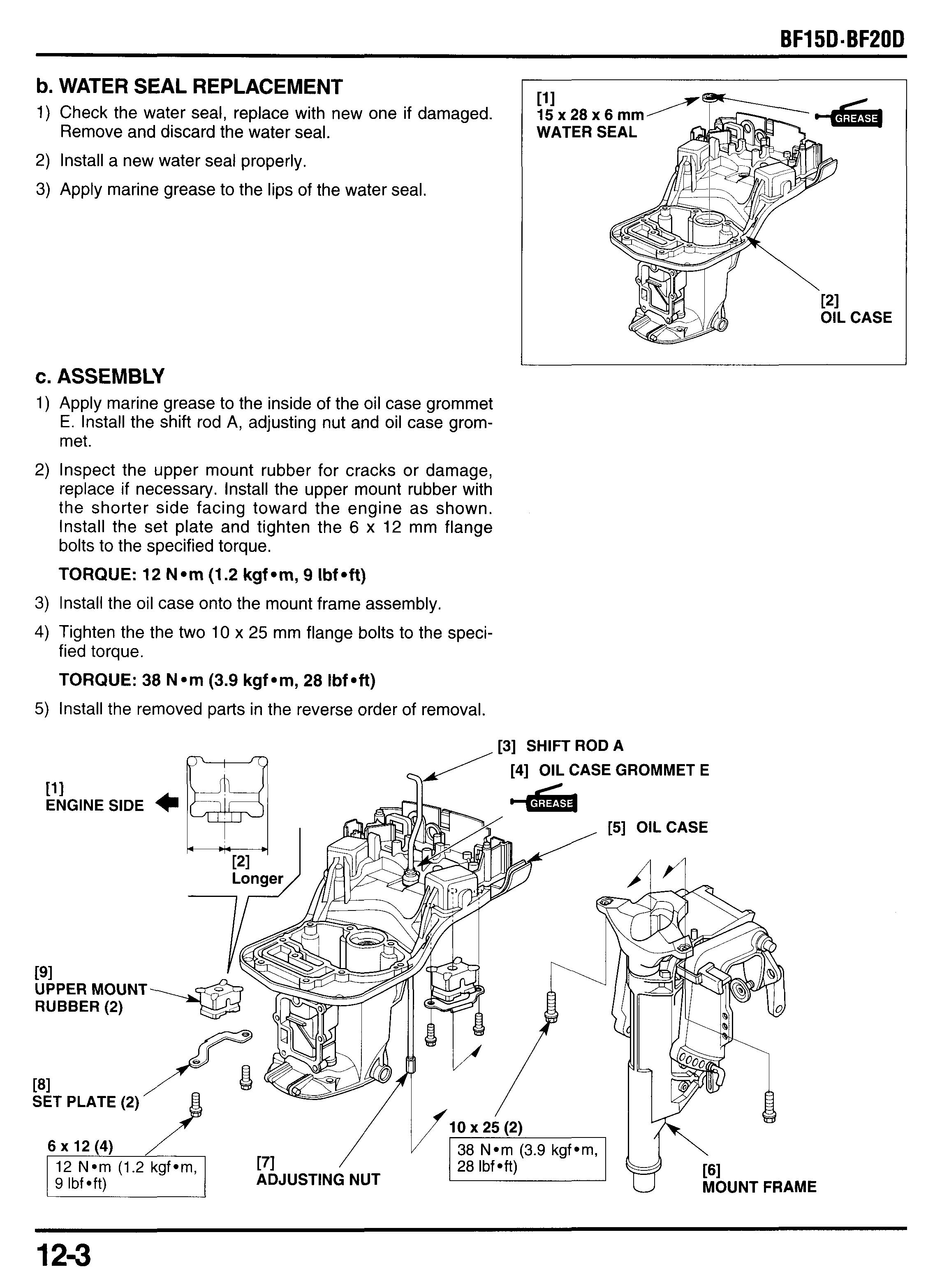
b. WATER SEAL REPLACEMENT
1) Check the water seal, replace with new one if damaged. Remove and discard the water seal.
2) Install a new water seal properly.
3) Apply marine grease to the lips of the water seal.
111 15 x 28 x 6 mm
c. ASSEMBLY
1) Apply marine grease to the inside of the oil case grommet E. Install the shift rod A, adjusting nut and oil case grommet.
2) Inspect the upper mount rubber for cracks or damage, replace if necessary. Install the upper mount rubber with the shorter side facing toward the engine as shown. Install the set plate and tighten the 6 x 12 mm flange bolts to the specified torque.
TORQUE: 12 N*m (1.2 kgf*m, 9 Ibf*ft)
3) Install the oil case onto the mount frame assembly.
4) Tighten the the two 10 x 25 mm flange bolts to the specified torque.
TORQUE: 38 N *rn (3.9 kgf Om, 28 Ibf Oft)
5) Install the removed parts in the reverse order of removal.
2. FRICTION ADJUSTING LEVER
a. DISASSEMBLY
The friction adjusting lever can be serviced with the oil case and engine installed. 111 8 mm
1) Remove the 8 mm self-locking nut.
2) Remove the 8 mm washer, friction adjusting lever, 8 mm nylon washer and friction block.
3) Remove the two 6 x 12 mm flange bolts and friction plate.
4) Remove the friction block. 121 x
b. ASSEMBLY
1) Before installation, check the disc surface of the friction block for wear. Replace if necessary.
2) Clean off grease or oil from the disc surfaces of the friction blocks and friction plate. Install one of the friction block onto the friction lever shaft by aligning the cutout with the boss on the swivel case and facing the disc surface toward the friction plate as shown.
FRICTION PLATE
4) Install the other friction block onto the friction lever shaft by aligning the cutout with the boss on the swivel case and facing the disc surface toward the friction plate.
5) Install the 8 mm nylon washer, friction adjusting lever and 8 mm washer.
6) Turn the adjusting lever to the right fully, and hold it in this position and tighten the 8 mm self-locking nut to the specified torque.
TORQUE: 2.5 N am (0.25 kgf am, 1.8 Ibf aft)
7) Check the starting torque by measuring the starting force by using a spring scale at the center of the tiller handle as shown.
Set the friction adjusting lever to right fully.
The motor should start to move with 20 N (20 kgf, 44 Ibf).
8) If NO, loosen the lock nut once, the retighten the self- locking nut to the specified torque.
8 mm NYLON WASHER [31 FRICTION ADJUSTING
3. MOUNT FRAME
a. REMOVALANSTALLATION
Refer to page for removal/installation:
- engine removaVinstal1ation(section 8).
- oil case removal (P. 12-2), installation (P. 12-3).
- friction adjusting lever removal (P. 12-4), installation (P. 12-
4 : Apply marine grease. 4). 4
121
(Apply to the all shaft section) 131 THRUST
Do not reuse, replace with new I
4. STERN BRACKET
a. REMOVAL
Tiller handle S type
Remove the following:
- oil case (P. 12-2).
- friction adjusting lever (P. 12-4).
- mount frame (P. 12-6).
Remove the adjusting rod.
Loosen the 8 mm self-locking nut, then remove the 6 mm hex. nut, 6 mm plain washer, 6 mm distance collar and 6 x 160 mm hex bolt.
Remove the 8 mm self-locking nut, 8 mm washer, tilt spring and 10 mm washer.
Remove the right stern bracket and 10 mm washers.
Remove the tilting bolt, 10 mm washer, carrying handle and left stern bracket.
Remove the tilting bushings if necessary.
Except tiller handle S type
Remove the following:
-oil case (P. 12-1).
- friction adjusting lever (P. 12-3).
- mount frame (P. 12-5).
Remove the adjusting rod.
Remove the tilting bolt cap and loosen the 7/8-14UNF self-locking nut, then remove the 8 mm self-locking nut, 8 mm plain washer, 8 mm distance collar and 8 x 163 mm hex. bolt.
Remove the 718-14UNF self-locking nut.
Remove the right stern bracket and 22 mm wave washer.
Remove the tilting shaft, 22 mm wave washer, carrying handle and left stern bracket.
Remove the tilting bushings if necessary.
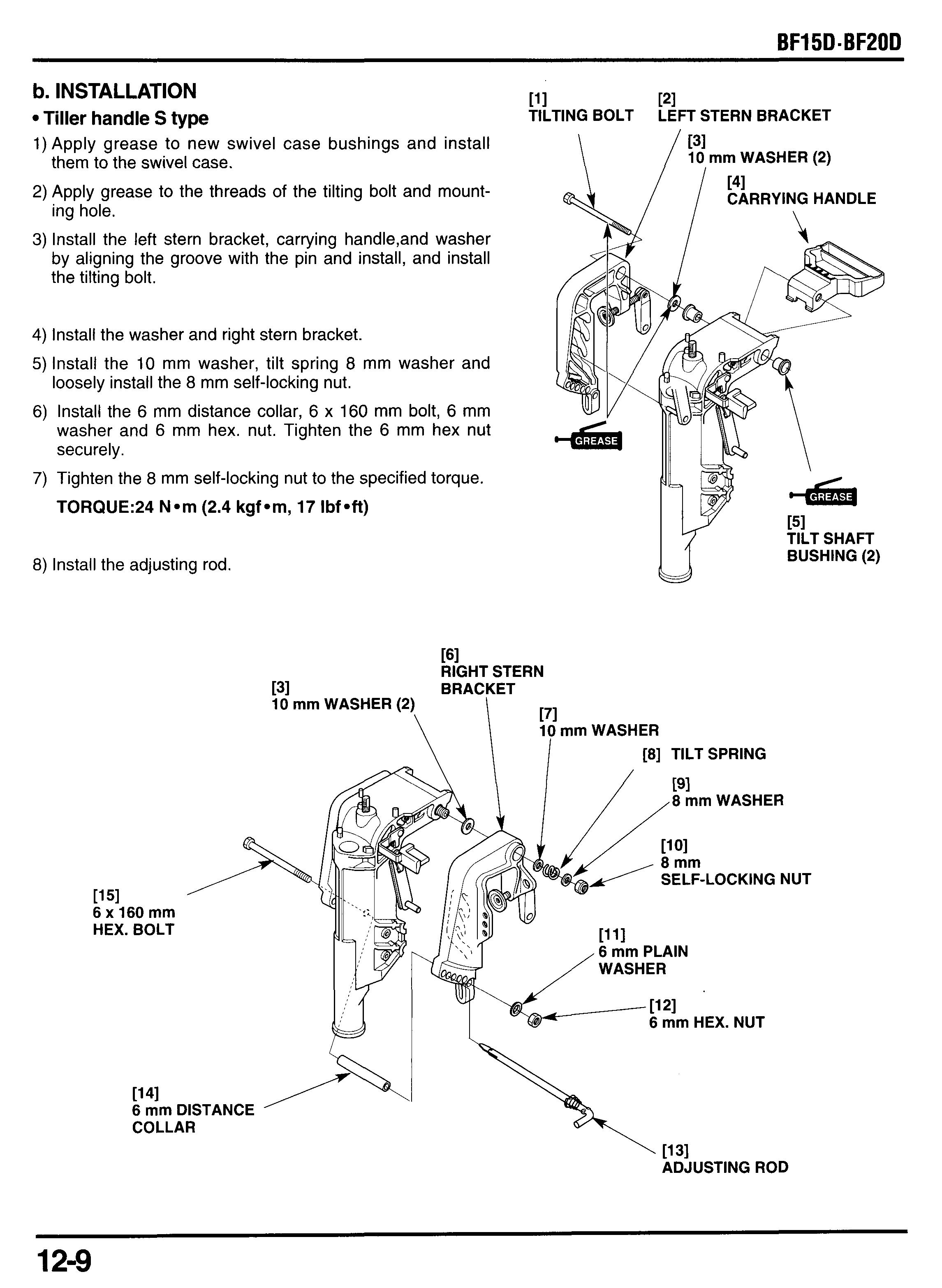
b. INSTALLATION
Tiller handle S type
1)Apply grease to new swivel case bushings and install them to the swivel case.
2) Apply grease to the threads of the tilting bolt and mounting hole.
3) Install the left stern bracket, carrying handle,and washer by aligning the groove with the pin and install, and install the tilting bolt.
4) Install the washer and right stern bracket.
5) Install the 10 mm washer, tilt spring 8 mm washer and loosely install the 8 mm self-locking nut.
6) Install the 6 mm distance collar, 6 x 160 mm bolt, 6 mm washer and 6 mm hex. nut. Tighten the 6 mm hex nut securely.
7) Tighten the 8 mm self-locking nut to the specified torque.
TORQUE:24 Nem (2.4 kgfem, 17 Ibfeft)
8) Install the adjusting rod.
Except tiller handle S type
I1) Apply grease to new swivel case bushings and install TILTING BOLT CAP TILTING them to the swivel case.
Apply grease to the threads of the tilting shaft, mounting hole and wave washer.
Install the left stern bracket, carrying handle, and wave washer by aligning the groove with the pin and install the tilting shaft.
Install the wave washer and right stern bracket.
Loosely install the 7/84 4UNF self-locking nut.
Install the 8 mm distance collar, 8 x 163 mm bolt, 8 mm washer and 8 mm self-locking nut. Tighten the 8 rnm selflocking nut to the specified torque.
TORQUE: 21 Nom (2.1 kgfom, 15 Ibfoft)
7)
Tighten the 7/8-14UNF self-locking nut to the specified torque.
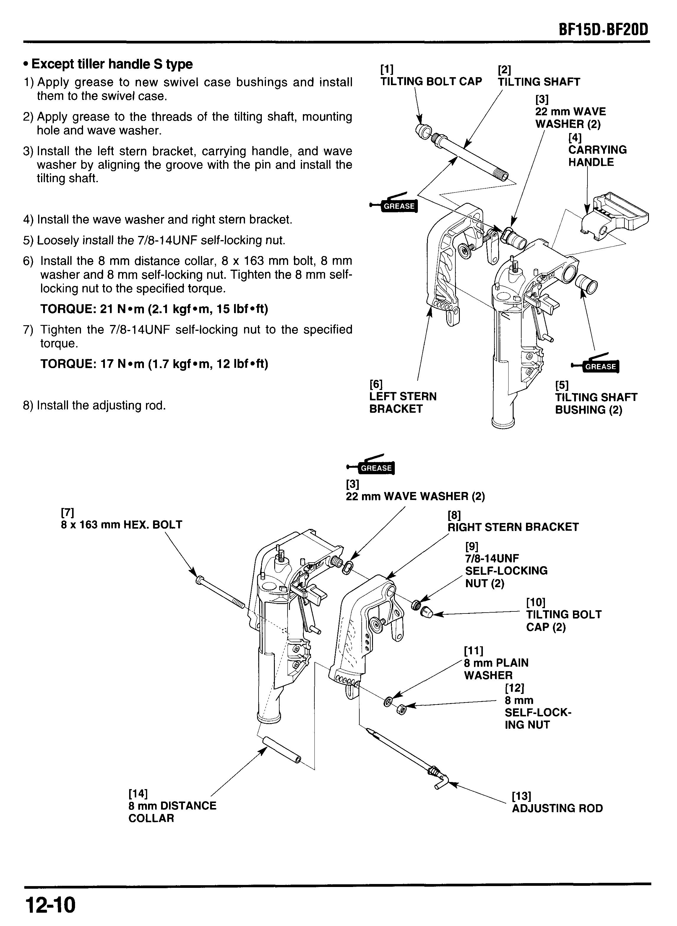
TORQUE: 17 Nom (1.7 kgfom, 12 Ibfoft)
Install the adjusting rod.
5. SWIVEL CASE
a. DISASSEMBLY
1) Raise up the tilt arm and unhook the tilt link spring from the hook on the swivel case then remove the tilt link spring.
2) Stretch the bent tabs of the lock washer and loosen the 6 mm hex. nut. Remove the 6 mm hex nut and lock washer, then push the tilt arm shaft slightly. Replace the lock washer with new one when reassembly.
3) Remove the tilt lever spring.
4) Drive out the 3 x 25 mm spring pin using a commercially available 3 mm pin driver and discard the spring pin. Replace the spring pin with new one when reassembly.
5) Remove the tilt shaft, tilt arm shaft bracket and tilt arm.
6) Check the tilt lever bushing B for wear or damage. replace if necessary.
7) Remove and discard the 2 mm cotter pin. Replace the 2 mm cotter pin with new one when reassembly. Don't reuse.
8) Remove the 6 mm washer and reverse lock shaft B, then remove the reverse lock hook and two reverse lock spring.
9) Remove and discard the 2 mm cotter pin. Replace the 2 mm cotter pin with new one when reassembly. Don't reuse.
10)Remove the 6 mm washer and reverse lock shaft A and reverse lock collar. Disengage the release rod from the reverse lock arm and remove the reverse lock arm.
11)Drive the 3 x 25 mm spring pin using a commercially available 3 mm pin driver until it comes clear of the upper side of the tilt lever bracket.
12)Drive the 3 x 22 mm spring pin according to the above procedure until it comes clear of upper side of the release rod bracket.
13)Pull the spring pins out of the bracket using a vise pliers and discard the spring pins. Replace the spring pins with new ones when reassembly.
14)Remove the tilt lever, then remove the release rod,
15)Check the tilt lever bushing A for wear or damage. release rod bracket tilt lever bracket. Replace if necessary.
1) Check the tilt lever bushing B for wear or damage, replace with new one if necessary.
2) Apply grease to the tilt lever bushing B.
3) Connect the release rod to the release rod bracket. Install the tilt lever, release rod bracket and tilt lever bracket.
4) Set the tilt lever, release rod bracket and tilt lever bracket in the position shown and set the 3 x 22 mm and 3 x 25 mm new spring pins.
5) Drive the spring pins using a commercially available pin driver until the both projected distances are equally as shown.
6) Engage the release rod to the reverse lock arm.
7) Apply grease to the shaft pivot holes of the swivel case and install the reverse lock arm, reverse lock collar and reverse lock shaft A.
8) Install the 6 mm plain washer and install a new 2 mm cotter pin, and spread the ends as shown.
9) Apply grease to the reverse lock hook pivot holes of the
10)lnstall the reverse lock springs, reverse lock hook and
1l)lnstall the 6 mm plain washer and install a new 2 mm cot- reverse lock arm. reverse lock shaft B. ter pin, and spread the ends as shown.
12)Check the tilt lever bushing A for wear or damage, replace with new one if necessary.
13)Apply grease to the tilt lever bushing B.
14)lnstall the tilt arm, tilt shaft and tilt shaft bracket.


