22 minute read
FLYWHEELRIMING BELT


1. FLYWHEEUCOILS
a. REMOVAL
1) Remove the following:
- engine cover (P. 5-1).
- left engine under cover (P. 5-2).
- right engine under cover (P. 5-3).
- recoil starter (P. 7-2).
- starter case B (P. 7-10).
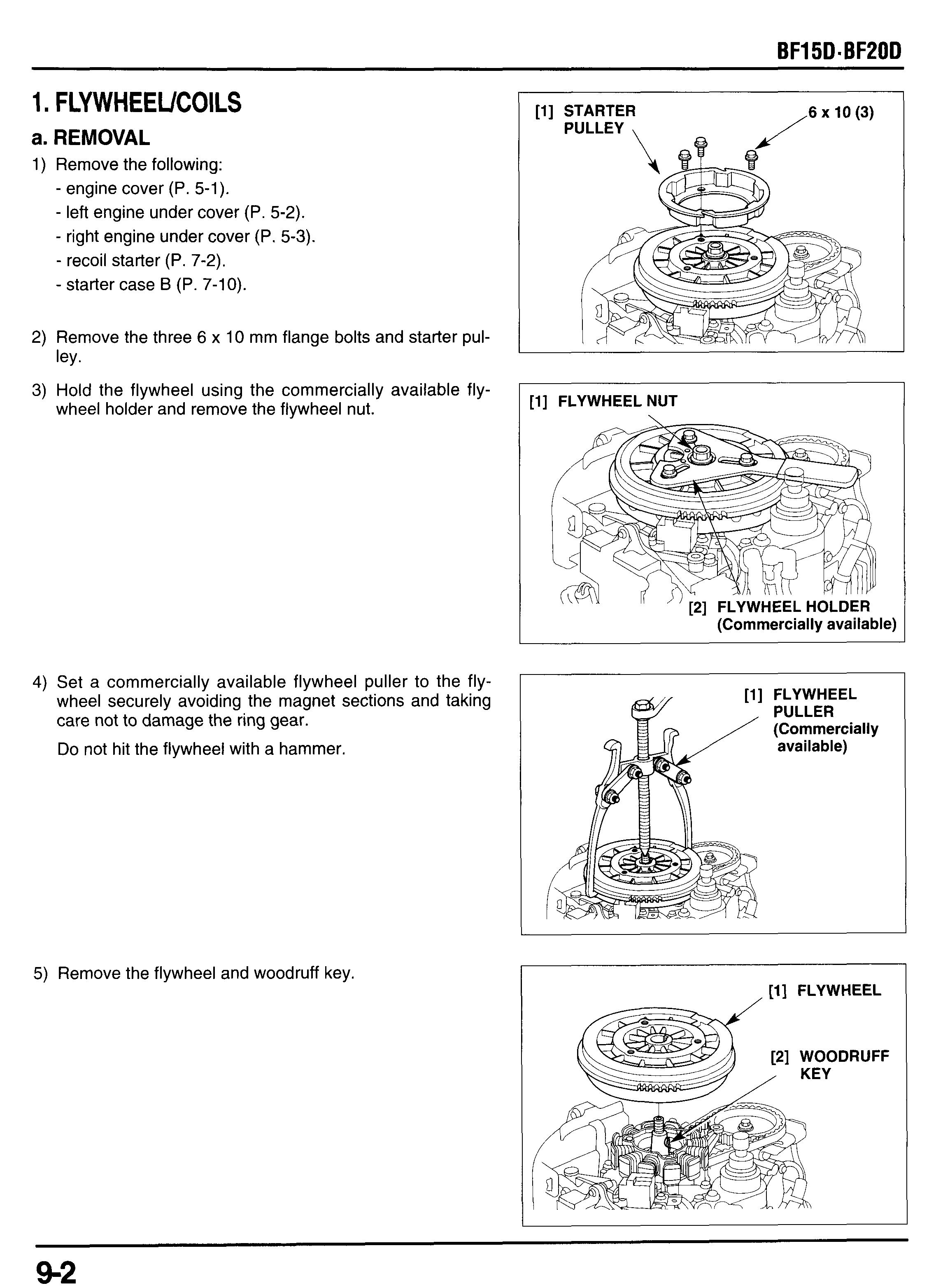
2) Remove the three 6 x 10 mm flange bolts and starter pul-
3) Hold the flywheel using the commercially available flyley. wheel holder and remove the flywheel nut.
4) Set a commercially available flywheel puller to the flywheel securely avoiding the magnet sections and taking care not to damage the ring gear. Do not hit the flywheel with a hammer.
5) Remove the flywheel and woodruff key.
6) Remove the connectors from the connector bracket A and disconnect the connectors.
See page 2-31 (Tiller handle type) or 2-33 (Remote control type) for connector locations.
7) Remove the 6 x 14 mm flange bolt and harness set plate.
8) Remove the 6 mm flange bolts and coil:
Type with 12A charge coil: two 6 x 52 mm, one 6 x 36 mm flange bolts and stator (charge/exciter coils).
Type with 6A charge coil: two 6 x 52 mm flange bolts and charge coil. two 6 x 52 mm flange bolts and exciter coil.
6
9) Remove the two 5 x 16 mm washer screws and ignition pulse generator.
b. INSPECTION
STATOR COILS (Type with 12A charge coil)
Measure the resistance between the each coil terminals. CoilTWire
CHARGE COIL (Type with 6A charge coil) resistance
Measure the resistance between the Gray terminals.
- 0.29 R
EXCITER COIL (Type without electric starter)
Measure the resistance between the Black and Green terminals.
1) Route the pulse generator wire under the pulse generator
2) Tighten the two 5 x 16 mm washer screws. bracket as shown and install the pulse generator.
3) Install the charge and exciter coils or stator coil:
12A charge coil type:
Install the stator coil and tighten the two 6 x 52 mm and one 6 x 36 mm flange bolts.
6A charge coil type: Install the charge and exciter coils and tighten the four 6 x 52 mm flange bolts.
4) Route the coil wires on the crankcase as shown and secure them with the set plate and tighten the 6 x 14 mm flange bolt.
5) Route the wire harness and connect the charge coil wire connectors. Set the connectors in the connector bracket A.
Refer to page 2-31 (Tiller handle type) or 2-33 (Remote control type) for connector location.
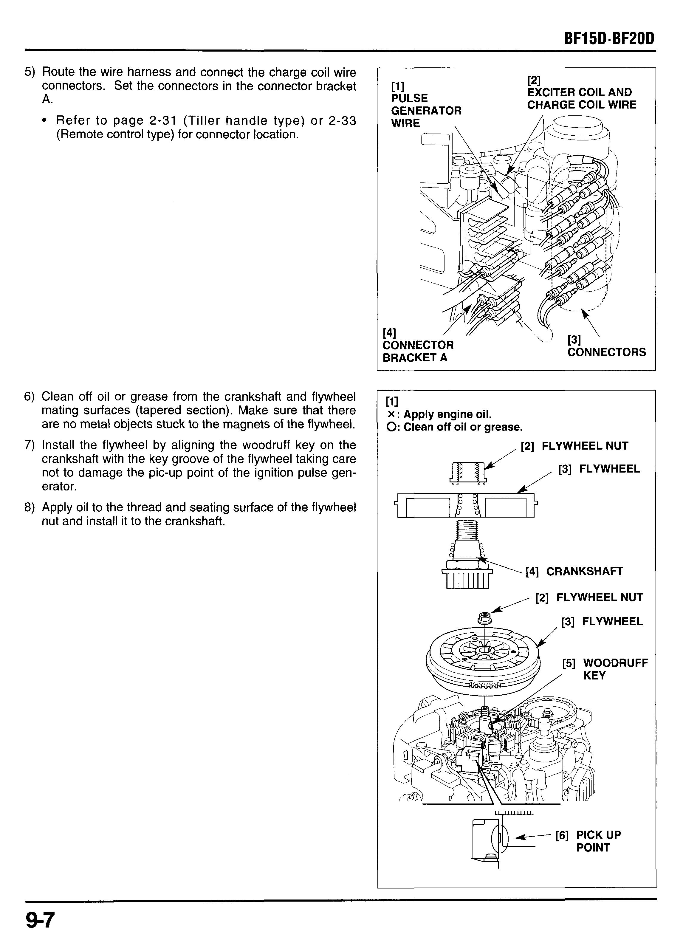
6) Clean off oil or grease from the crankshaft and flywheel mating surfaces (tapered section). Make sure that there are no metal objects stuck to the magnets of the flywheel.
7) Install the flywheel by aligning the woodruff key on the crankshaft with the key groove of the flywheel taking care not to damage the pic-up point of the ignition pulse generator.
8) Apply oil to the thread and seating surface of the flywheel nut and install it to the crankshaft.
111 X : Apply engine oil. 0:Clean off oil or grease. [2] FLYWHEEL
9) Hold the flywheel using the commercially available flywheel holder and tighten the flywheel nut.
TORQUE: 132 N*m (13.5 kgf*m, 98 Ibf*ft)
10) Remove the flywheel holder. Install the starter pulley and tighten the three 6 x 12 mm flange bolts.
TORQUE: 11 N*m (1.1 kgf*m, 8 Ibfaft)
1l)lnstall the following removed parts in the reverse order of removal.
- starter case 6 (P. 7-10).
- recoil starter (P. 7-9).
- neutral start cable (P. 7-1).
- left and right engine under covers (P. 5-2 and 3).
- engine cover.
2. TIMING BELTlPULLEYS
a. REMOVAL
1) Remove the following:
- engine cover (P. 5-1).
- left engine under cover (P. 5-2).
- right engine under cover (P. 5-3).
- recoil starter (P. 7-2)
2) If it is necessary to remove the timing belt driven pulley, loosen the timing belt driven pulley mounting bolt.
3) Remove the flywheel and coils (P. 9-2).
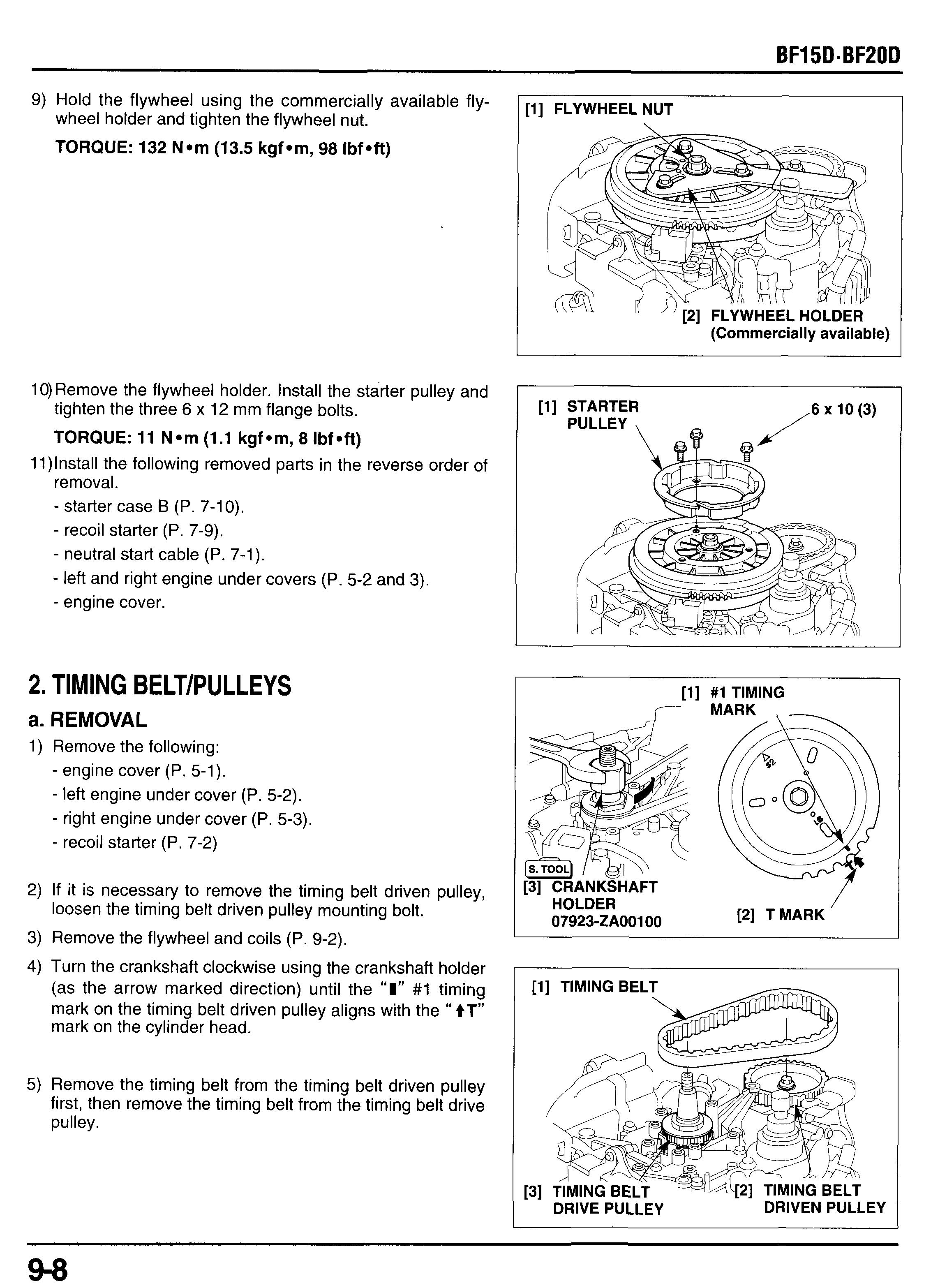
4) Turn the crankshaft clockwise using the Crankshaft holder (as the arrow marked direction) until the “I” #l timing mark on the timing belt driven pulley aligns with the “+T” mark on the cylinder head.
5) Remove the timing belt from the timing belt driven pulley first, then remove the timing belt from the timing belt drive pulley.
6) Hold the crankshaft using the crankshaft holder as shown and loosen the 30 mm lock nut.
7) Remove the 30 mm lock nut, timing belt drive pulley,
8) Remove the 6 x 20 mm flange bolt and timing belt driven guide plates and woodruff key. pulley
\
b. INSTALLATION
[6] TIMING BELT DRIVE PULLEY
[5] GUIDE PLATE (2) ,
[2] TIMING BELT
1) Disconnect the spark plug caps and remove the spark plugs.
2) Install the timing belt driven pulley on the camshaft by aligning the key of the pulley with the key groove of the camshaft.
3) Apply oil to the thread and seating surface of the 6 x 20 mm flange bolt and tighten it to the specified torque.
TORQUE: 16 N*m (1.6 kgfom, 12 Ibfoft)
4) Make sure that the “I” #1 timing mark on the timing belt driven pulley aligns with the ‘‘ +T” mark on the cylinder head. If necessary align the mark by turning the driven pulley counterclockwise.
16 N-m (1.6 kgf-m, 12 Ibf-ft)
5) Install the woodruff key onto the crankshaft and install the timing belt drive pulley and guide plates in the direction shown.
6) Apply oil to the thread and seating surface of the 30 mm lock nut, and install it loosely onto the crankshaft.
[3] 30 mm LOCK NUT 69 N-m (7.0 kgf-m, 51 Ibf-ft)
7) Hold the crankshaft with the crankshaft holder and tighten the 30 mm lock nut to the specified torque.
TORQUE: 69 N*m (7.0kgf ern, 51 Ibf Oft)
8) Make sure that the woodruff key on the crankshaft aligns with the center line of the cylinder as shown (woodruff key should align with the “I”mark on the crankcase cover). If necessary, turn the crankshaft clockwise using the crankshaft holder.
9) Che k the timing belt, replace the timing belt if it is worn or damaged. Check the timing belt and the related parts for oil and grease. If contaminated with oil or grease, clean the parts and replace the timing belt with new one.
10)lnstall the timing belt on the timing belt drive pulley first and then on the driven pulley taking care not to allow the alignment marks to come out of alignment.
11)After installation, be sure that the alignment marks are in the proper alignment.
12)Reinstall the removed parts:
- flywheel (P. 9-9).
- pulse generator (P. 9-6).
- charge coil (P. 9-6)
- starter case B (P. 7-10).
- recoil starter (P. 7-9).
- neutral start cable (P. 7-1).
- left and right engine under covers (P. 5-2 and 3).
- engine cover.
1. CYLINDER HEAD REMOVAL
2. OIL PUMP
3. CYLINDER HEAD DISASSEMBLY
4. VALVE SEAT REFACING
5. CYLINDER HEAD ASSEMBLY
6. CYLINDER HEAD INSTALLATION
1. CYLINDER HEAD REMOVAL
Cylinder head assembly can be serviced with the engine installed on the frame.
1) Remove the oil filler cap and oil drain bolt, and drain the engine oil into a suitable container (P. 3-3).
2) Remove the following pars:
- engine cover (P. 5-1).
- left engine under cover (P. 5-2).
- right engine under cover (P. 5-3).
- recoil starter (P. 7-2).
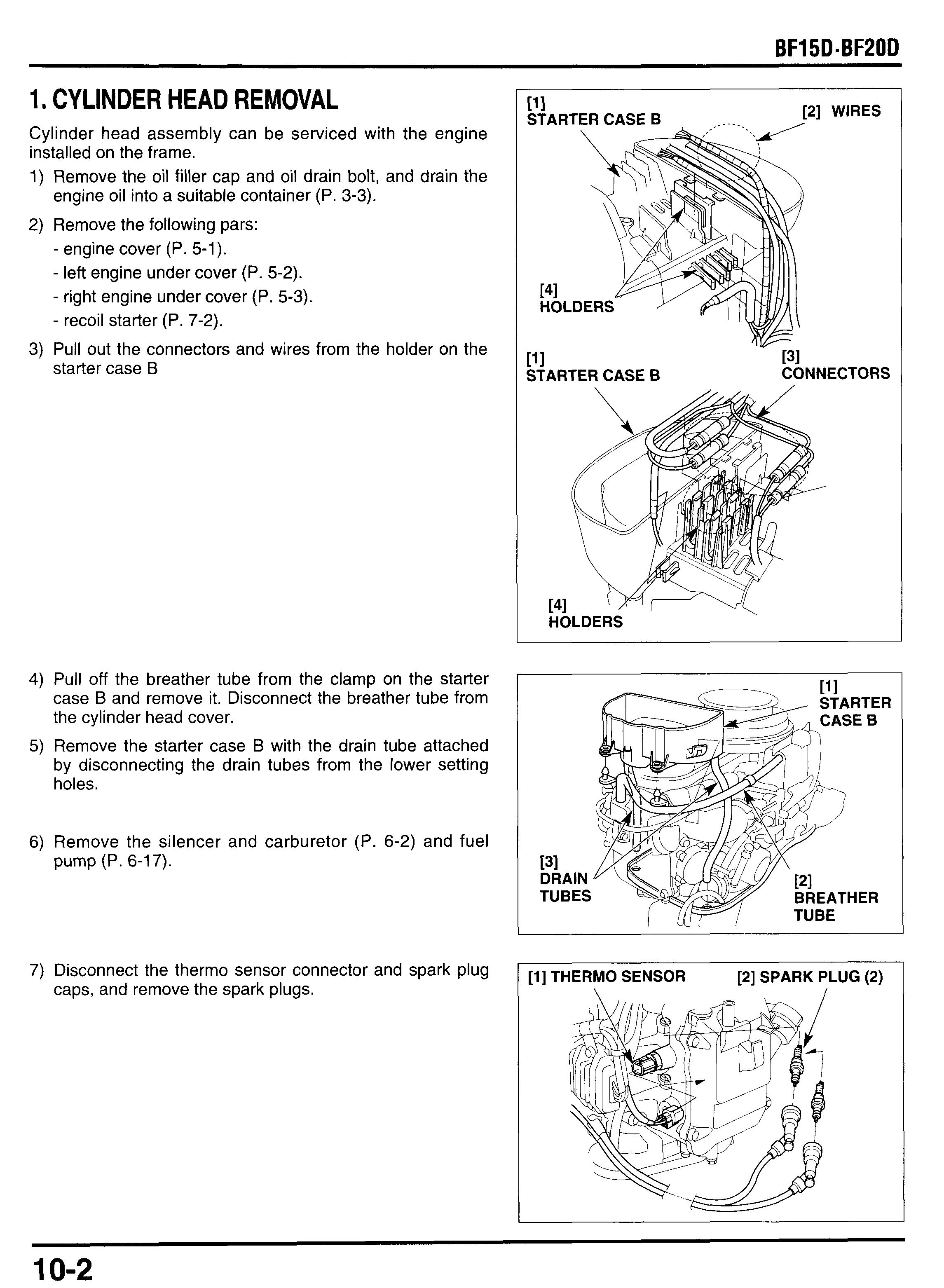
3) Pull out the connectors and wires from the holder on the starter case B pmE
4) Pull off the breather tube from the clamp on the starter case B and remove it. Disconnect the breather tube from the cylinder head cover.
5) Remove the starter case B with the drain tube attached by disconnecting the drain tubes from the lower setting holes.
6) Remove the silencer and carburetor (P. 6-2) and fuel pump (P. 6-17).
7) Disconnect the thermo sensor connector and spark plug caps, and remove the spark plugs.
8) Loosen the timing belt driven pulley mounting bolt.
9) Turn the crankshaft clockwise by turning the flywheel clockwise (in the arrow marked direction) until the “I” #1 timing mark on the timing belt driven pulley aligns with the “ tT” mark on the cylinder head.
Don’t turn the flywheel counterclockwise or the water pump may be damage.
10)Remove the timing belt from the timing belt driven pulley
11)Remove the pulley bolt and timing belt driven pulley taking care not to damage the timing belt.
12)Remove the four head cover bolts, cylinder head cover and head cover gasket.
13)Turn the fuel pump lifter as shown.
14) Loosen the cylinder head bolts in a crisscross pattern in 2 - 3 steps, then remove the cylinder head bolts.
15)Remove the cylinder head, gasket and dowel pins.
2. OIL PUMP
a. DISASSEMBLY
1) Remove the three 6 x 35 mm flange bolts and remove the oil pump assembly and oil pump O-ring. Discard the 0ring, replace with new one when reassembly.
2) Remove the two 5 x 12 mm flange bolts and remove the oil pump cover and cover O-ring. Discard the O-ring, replace with new one when reassembly.
3) Remove the inner rotor, pump shaft, 4 x 15.8 mm pin and 11 mm thrust washer.
4) Remove the outer rotor.
b. INSPECTION
Measure the oil pump rotor tip clearance with the pump shaft installed.
OUTER ROTOR-TO-BODY CLEARANCE
Measure the outer rotor-to-body clearance with the pump shaft installed.
ROTOR-TO-BODY SIDE CLEARANCE
Measure the rotor-to-body side clearance.
I Standard Service limit I
OIL PUMP BODY DEPTH
Measure the pump body depth. I
Outer Rotor Height
Measure the outer rotor height.
CAMSHAFT JOURNAL I.D.
Measure and record the oil pump body camshaft journal I.D.
c. ASSEMBLY
1) Clean the all disassembled parts with solvent.
2) Install the 4 x 15.8 mm pin to the oil pump shaft.
3) Install the 11 mm thrust washer, pump shaft with the 4 mm pin attached to the inner rotor by aligning the pin with the groove of the inner rotor.
4) Install the outer rotor, and install the inner rotor with the pump shaft, washer, and pin attached to the pump body.
5) Install a new pump cover O-ring and pump cover, then tighten the 5 x 12 mm flange bolts.
TORQUE: 5 Nom (0.5 kgf*m, 3.6 Ibf*ft)
c. INSTALLATION
1) Install a new oil pump O-ring to the oil pump body.
2) Install the oil pump assembly by aligning the groove of the oil pump shaft with the pin on the camshaft as shown.
3) Tighten the three 6 x 35 mm flange bolt to the specified torque.
TORQUE: 11 Nom (1.1 kgfom, 8 Ibfoft)
3. CYLINDER HEAD DISASSEMBLY
Before removing the cylinder head, check the camshaft axial play (P. 10-10).
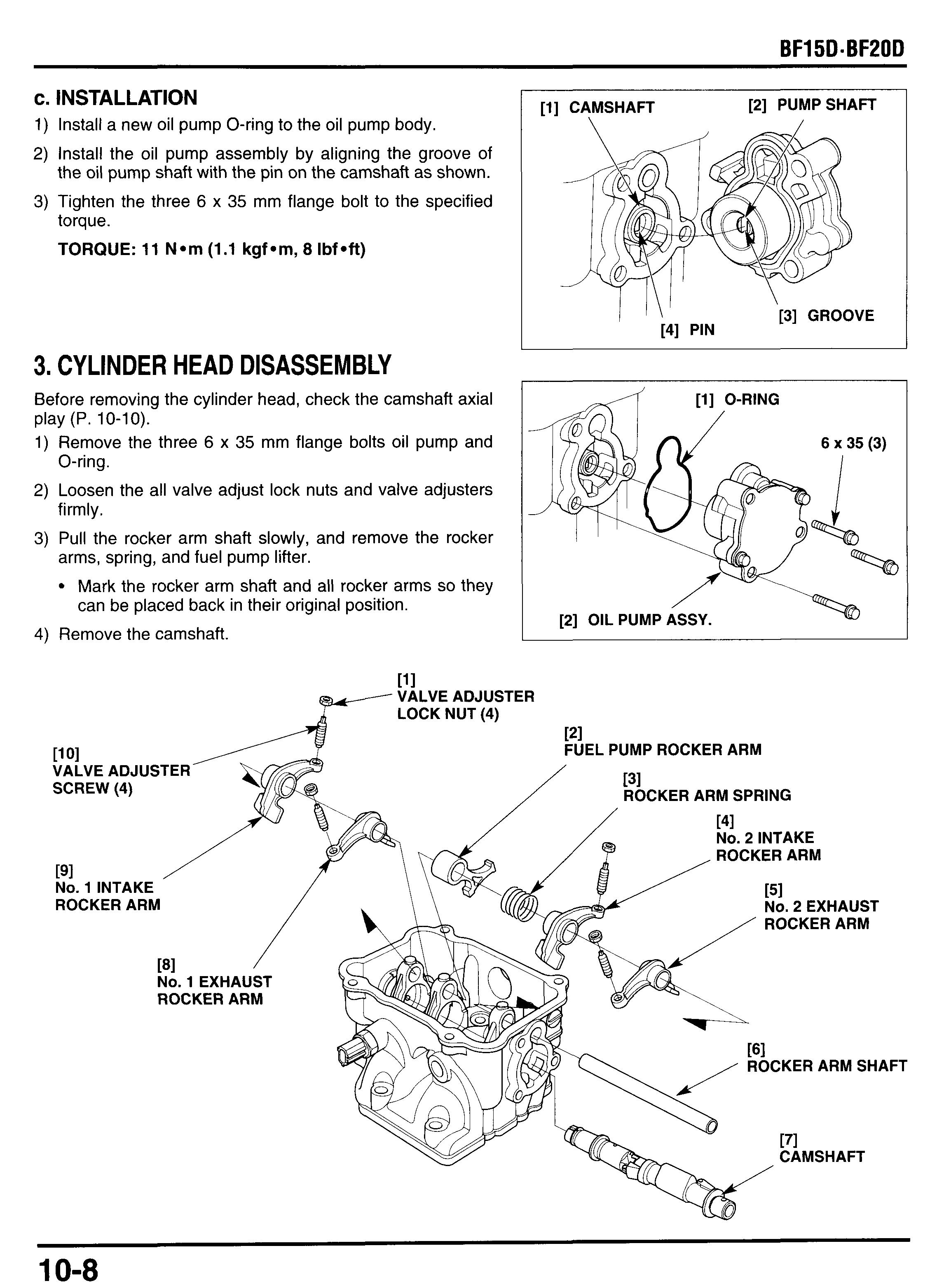
1) Remove the three 6 x 35 mm flange bolts oil pump and O-ring.
2) Loosen the all valve adjust lock nuts and valve adjusters firmly.
3) Pull the rocker arm shaft slowly, and remove the rocker arms, spring, and fuel pump lifter.
Mark the rocker arm shaft and all rocker arms so they can be placed back in their original position.
4) Remove the camshaft.
5) Set the valve spring compressor and compress the valve spring.
6) Remove the valve cotters, then release the valve spring compressor and remove the spring retainer, valve spring, valve spring seat and valve. Remove the valve stem seal if necessary.
Valve stem seal must be replaced with new one when disassembled.
Store all parts according the cylinder so they can be placed back in their original position.
7) Inspect the oil sea for damage, replace if necessary
8) Remove the thermo sensor.
a. INSPECTION
Camshaft Axial Play
Perform this inspection with the rocker arms, rocker arm shaft, and oil pump installed.
1) Loosen the valve adjust lock nuts and valve adjusters
2) Turn the camshaft so the key groove facing toward the
ROCKER ARMS fully. cylinder head cover as shown. moving the camshaft up and down. I Standard Servicelimit -1 Service limit
1) Inspect the sliding surface of the rocker arms for wear or damaged where they contact the camshaft.
3) Measure and record the I.D. of the rocker arm.
0.05 - 0.20 mm 0.30 mm 1 (0.002 - 0.008 in) 13.000 - 13.080 mm (0.51 18 - 0.51 50 in)
2) Inspect the contact surface of the valve adjuster for wear or damage.
13.10 mm (0.516 in) I- Standard 13.000 - 13.018 mm (0.51 18 - 0.5125 in) 13.04 mm (0.513 in) 104 0
Rocker Arm Shaft
1) Measure and record the O.D. of the rocker arm shaft.
2) Calculate the rocker arm shaft-to-rocker arm and fuel pump lifter-to-rockerarm shaft clearance.
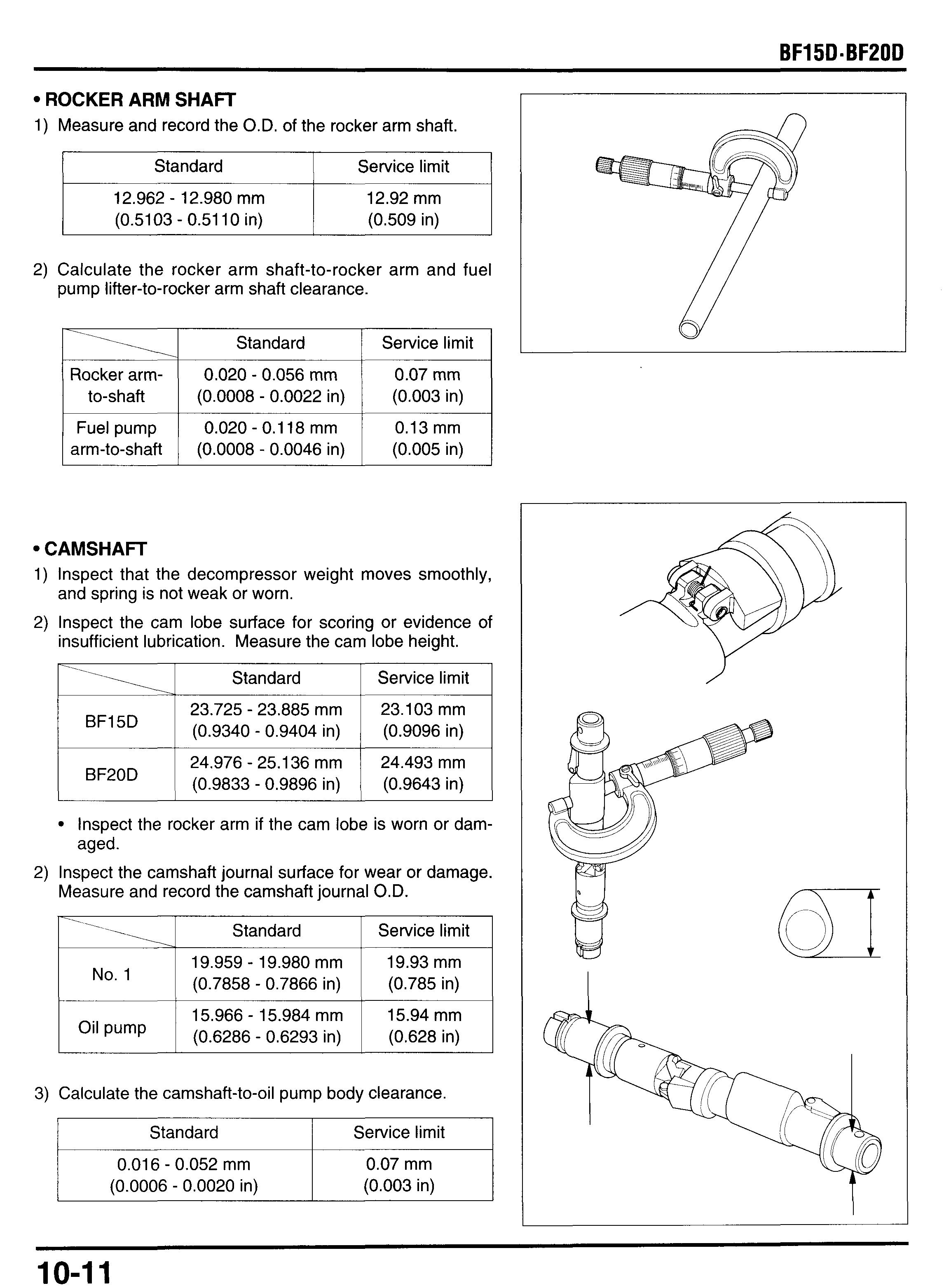
Camshaft
1) Inspect that the decompressor weight moves smoothly, and spring is not weak or worn.
2) Inspect the cam lobe surface for scoring or evidence of insufficient lubrication. Measure the cam lobe height.
3alculate the camshaft-to-oilpump body clearance.
Cylinder Head
1) Remove the carbon deposits from the combustion cham- ber. and feeler gauge.
2) Check the spark plug hole and valve are for cracks.
Service limit (0.003 in) 0.020 - 0.062 mm (0.0008 - 0.0024 in)
VALVE SEATS
1) Thoroughly clean the combustion chamber and valve seats to remove carbon deposits.
2) Apply a light coat of Prussian Blue compound or erasable felt-tipped marker ink to the valve seats.
10-12
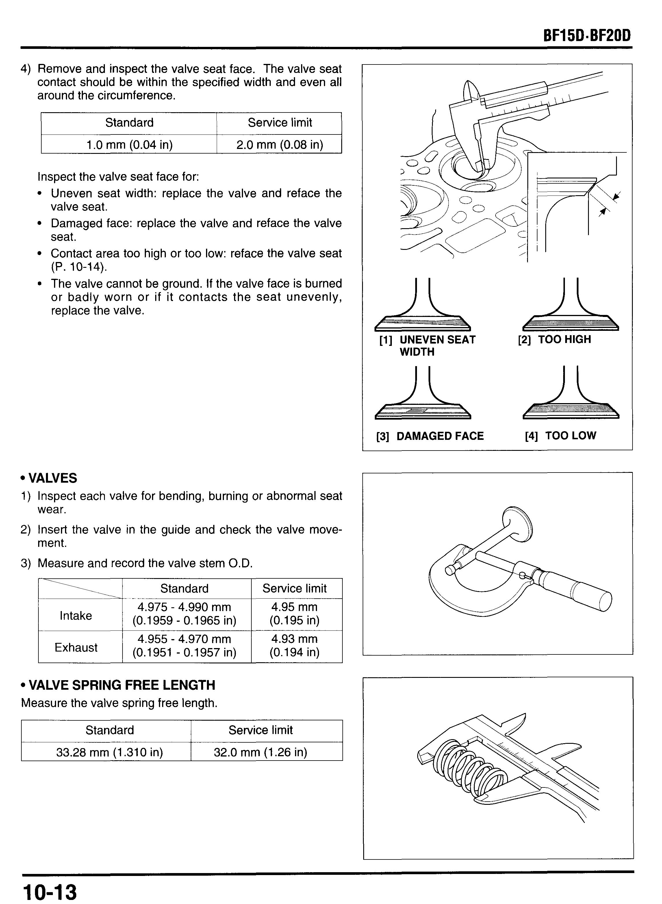
4) Remove and inspect the valve seat face. The valve seat contact should be within the specified width and even all around the circumference.
Inspect the valve seat face for:
Uneven seat width: replace the valve and reface the valve seat.
Damaged face: replace the valve and reface the valve seat.
Contact area too high or too low: reface the valve seat
(P. 10-14). [l] UNEVEN SEAT [2] TOO HIGH WIDTH [3] DAMAGED FACE [4] TOOLOW 10-13
Valve Guides
1) Ream the valve guide to remove any deposits before checking the valve guide I.D.
Insert the valve guide reamer from the combustion chamber side of the head and always rotate the reamer clockwise.
2) Measure and record the valve guide I.D.
3) Substrate each valve stem O.D. from the corresponding guide I.D. to obtain the stem-to-guide clearance.
4) If the stem-to-guide clearance is out of the specification, determine if a new valve with standard dimensions would bring the clearance within tolerance. If so, replace the valve as necessary. If the clearance is out of the specification with the new valve, replace the cylinder head as assembly.
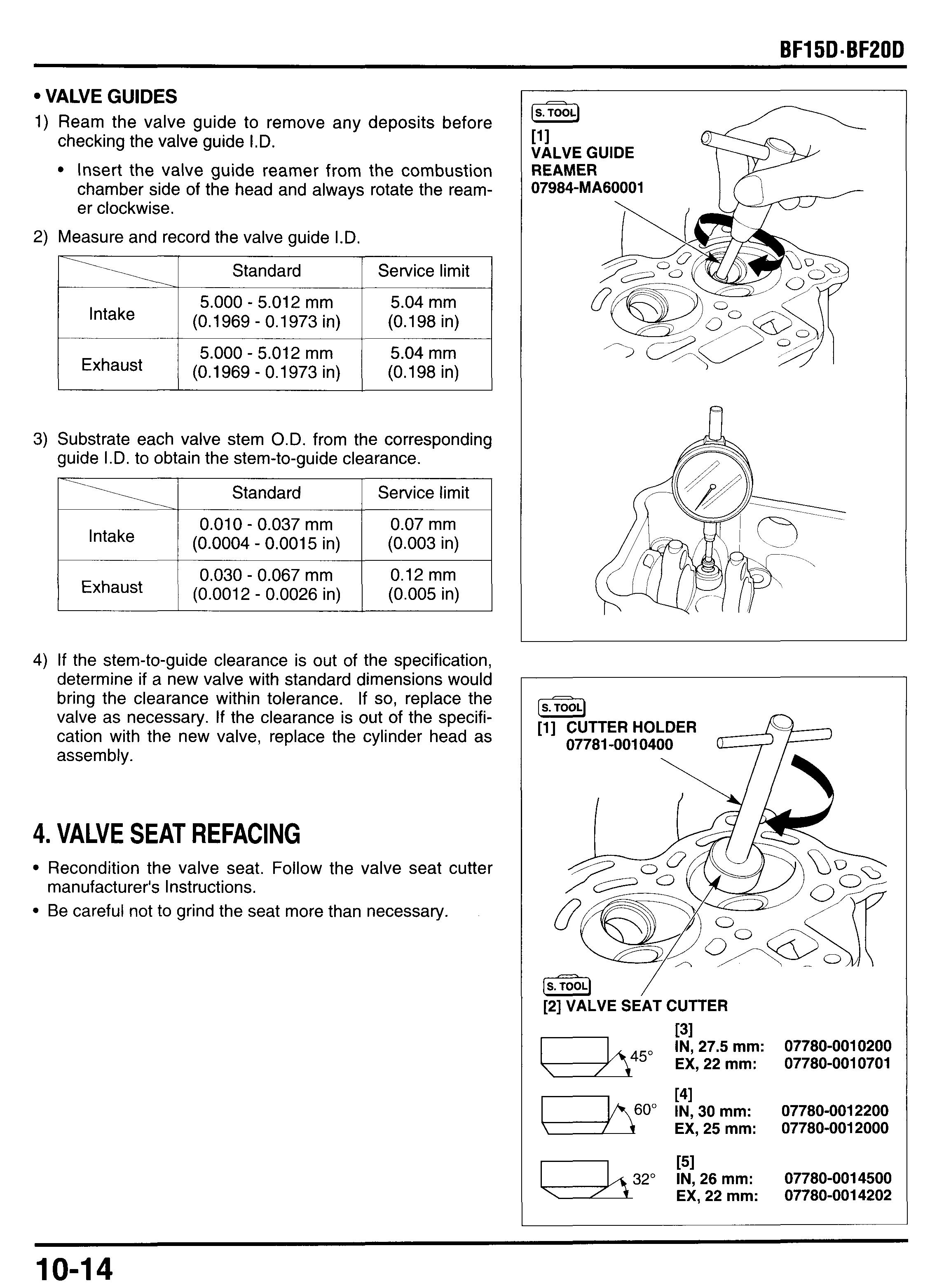
4. VALVE SEAT REFACING
Recondition the valve seat. Follow the valve seat cutter Be careful not to grind the seat more than necessary. manufacturer's Instructions.
1) Using a 45" cutter, remove enough material to produce a smooth and concentric seat. Turn the cutter clockwise, never counterclockwise. Continue to turn the cutter as you lift it from the valve seat.
2) Use the 32" and 60" cutter to narrow and adjust the valve seat so that it contacts the middle of the valve face.
The 32" cutter removes material from the top edge. The 60" cutter removes material from the bottom edge.
3) Be sure that the width of the finished valve seat is within specification.
I Standard valve 0.9 - 1.1 mm (0.035 - 0.043 in) seat width
4) Make a light pass with 45" cutter to remove any possible burrs at the edges of the seat.
5) After resurfacing the seats, inspect for even valve seating. Apply Prussian Blue compound or erasable felt-tipped marker ink to the valve faces. Insert the valves, and then lift them and snap them closed against their seats several times. Be sure the valve does not rotate on the seat. The seating surface, as shown by the transferred marking compound, should have good contact all the way around.
If the contact position is too high, resurface with the 32" cutter and then to the specified width with the 45" cutter.
If the contact position is too low, resurface with the 60" cutter and then to the specified width with the 45" cutter.
6) Lap the valves into their seats, using a hand valve lapper
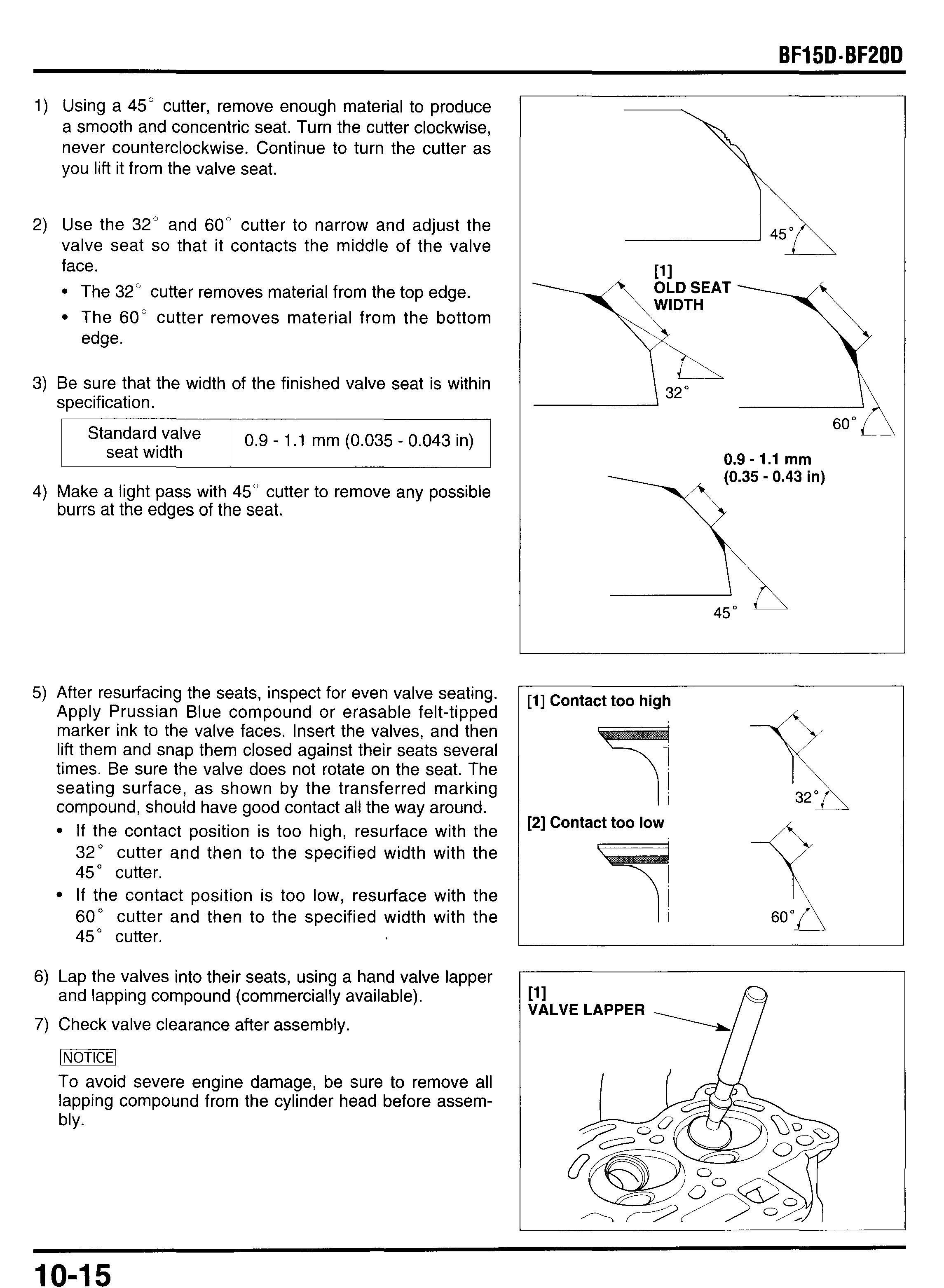
7) Check valve clearance after assembly. and lapping compound (commercially available).
To avoid severe engine damage, be sure to remove all lapping compound from the cylinder head before assembly.
4. CYLINDER HEAD ASSEMBLY
1) Clean the cylinder head with a solvent and blow through al oil passages with compressed air.
2) Install a new O-ring onto the thermo sensor.
3) Apply liquid sealant (Three bond #1201, #1215 or equivalent) to the thread of the thermo sensor. Then install the thermo sensor and tighten it to the specified torque.
TORQUE: 18 N*m (1.8 kgf*m, 13 Ibfoft)
4) Install a new oil seal, then apply grease to the lip of the oil seal.
5) Install the valve spring seats and new stem seals.
6) Lubricate the valve stem with molybudenum oil solution and insert the valve into the valve guide by turning the valve slowly to prevent damage to the stem seal.
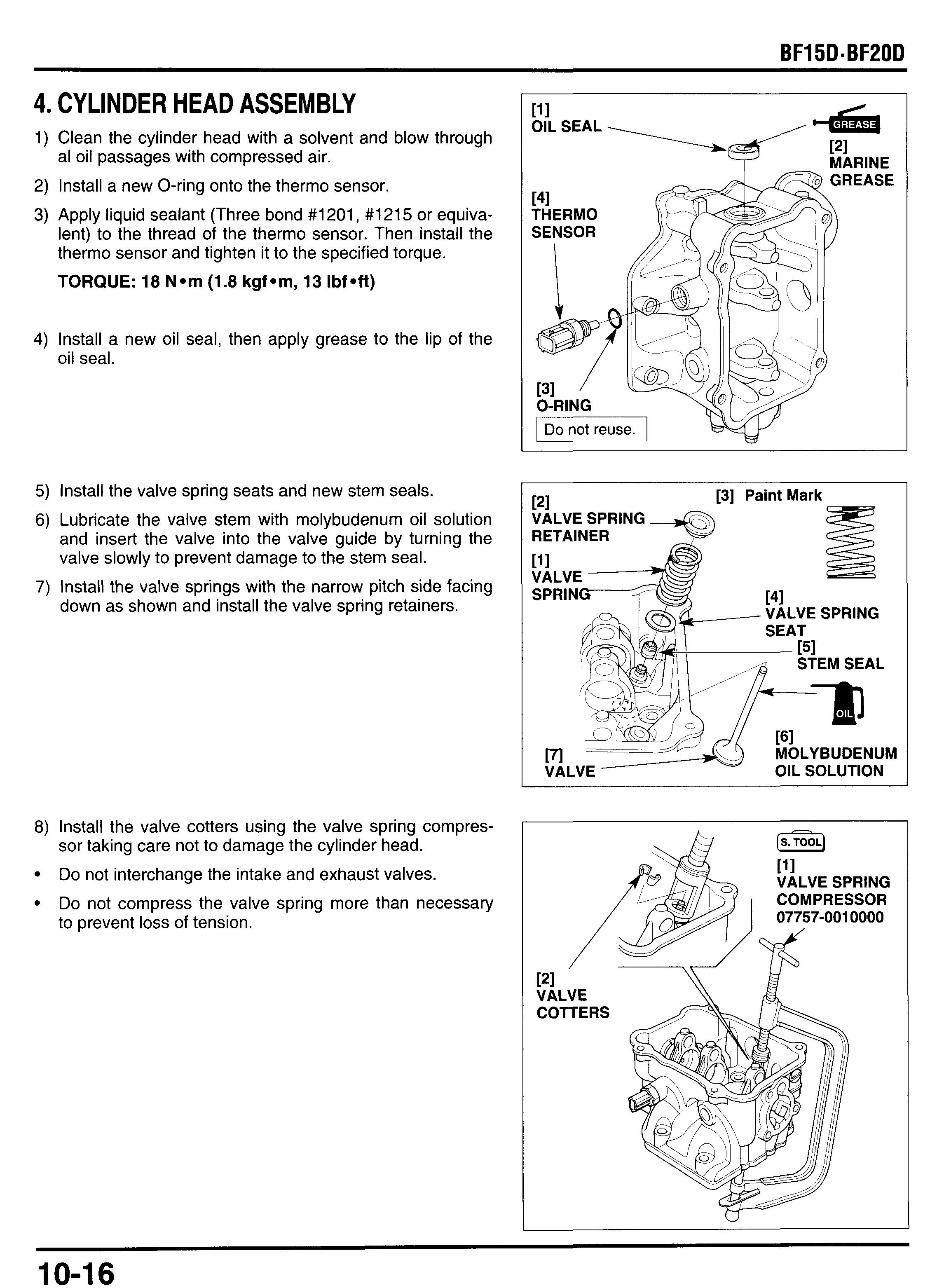
7) Install the valve springs with the narrow pitch side facing down as shown and install the valve spring retainers.
8) Install the valve cotters using the valve spring compressor taking care not to damage the cylinder head. Do not interchange the intake and exhaust valves. Do not compress the valve spring more than necessary to prevent loss of tension.
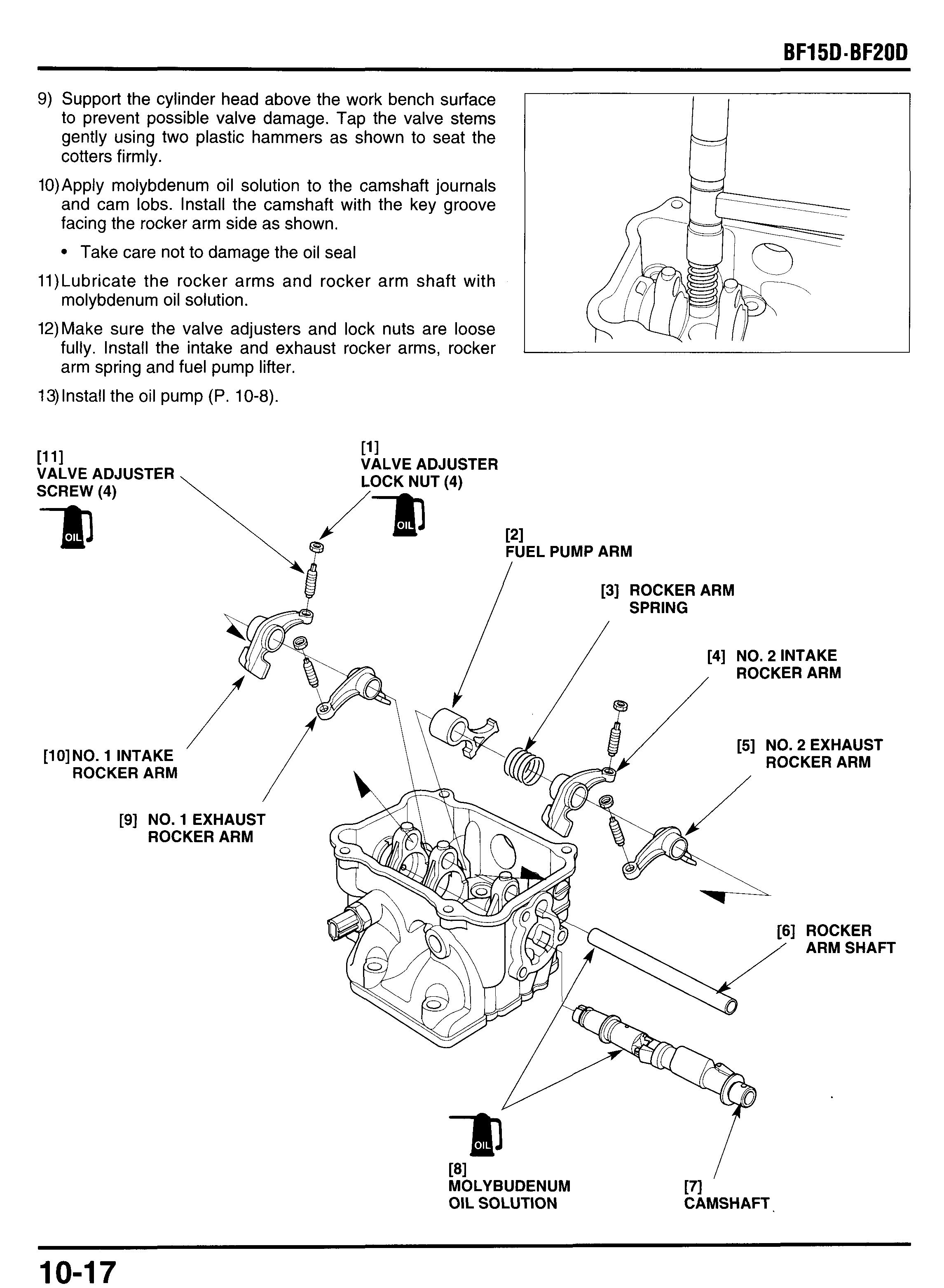
9) Support the cylinder head above the work bench surface to prevent possible valve damage. Tap the valve stems gently using two plastic hammers as shown to seat the cotters firmly.
10)Apply molybdenum oil solution to the camshaft journals and cam lobs. Install the camshaft with the key groove facing the rocker arm side as shown.
Take care not to damage the oil seal
11)Lubricate the rocker arms and rocker arm shaft with molybdenum oil solution.
12)Make sure the valve adjusters and lock nuts are loose fully. Install the intake and exhaust rocker arms, rocker arm spring and fuel pump lifter.
13)lnstall the oil pump (P. 10-8).
6. CYLINDER HEAD INSTALLATION
1) Install the two dowel pins and a new cylinder head gas-
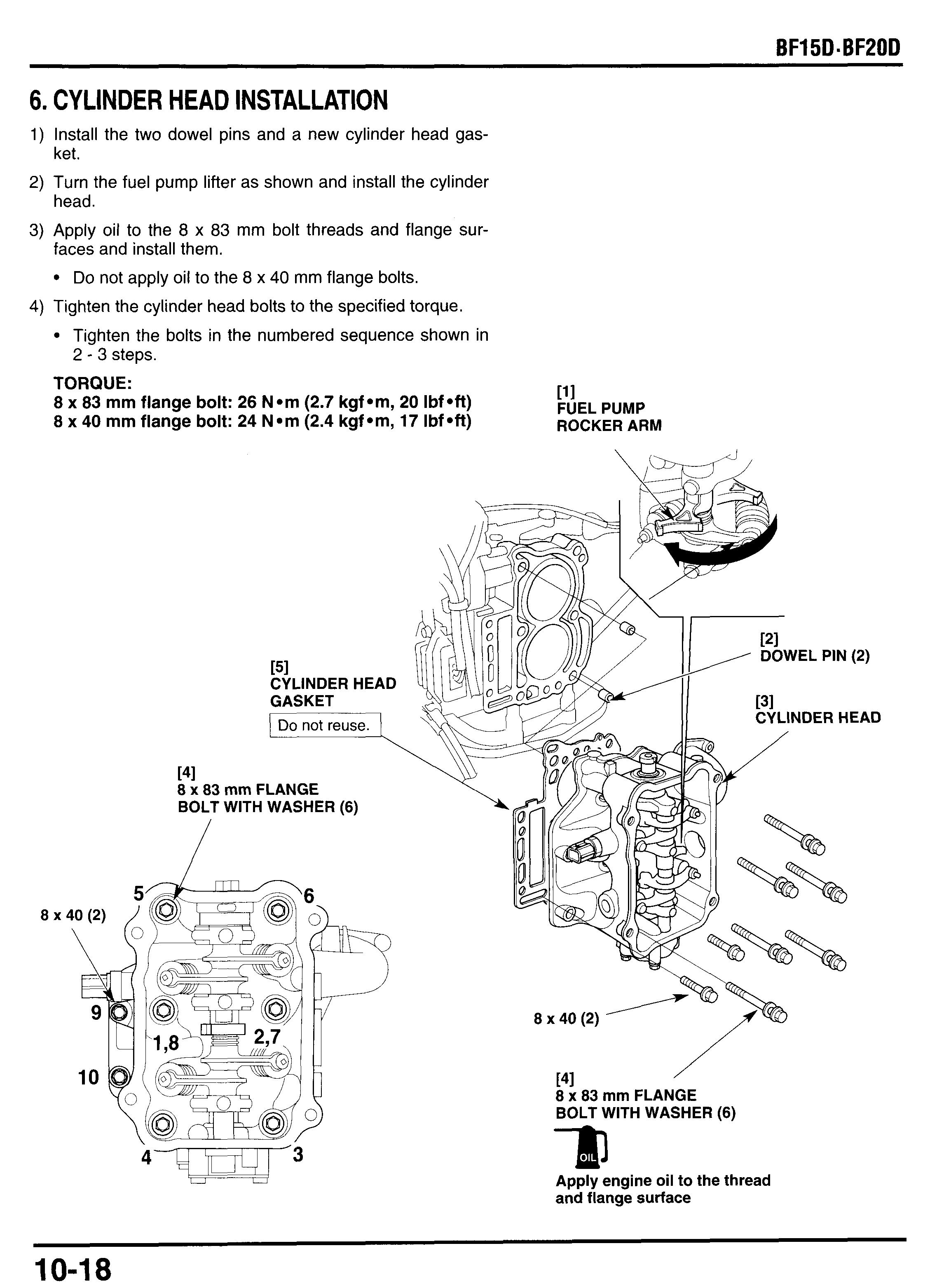
2) Turn the fuel pump lifter as shown and install the cylinder
3) Apply oil to the 8 x 83 mm bolt threads and flange sur- ket. head. faces and install them.
Do not apply oil to the 8 x 40 mm flange bolts.
4) Tighten the cylinder head bolts to the specified torque.
Tighten the bolts in the numbered sequence shown in 2 - 3 steps.
TORQUE:
8 x 83 mm flange bolt: 26 N*m (2.7 kgf*m, 20 Ibf *ft)
8 x 40 mm flange bolt: 24 N.m (2.4 kgf*m, 17 Ibfmft)
151 CYLINDER HEAD GASKET I DO not reuse.
[41 8 x 83 mm FLANGE BOLT WITH WASHER (6)
8 x 40 (2)
141 8 x 83 mm FLANGE TITH WASHER (6)
Apply engine oil to the thread and flange surface
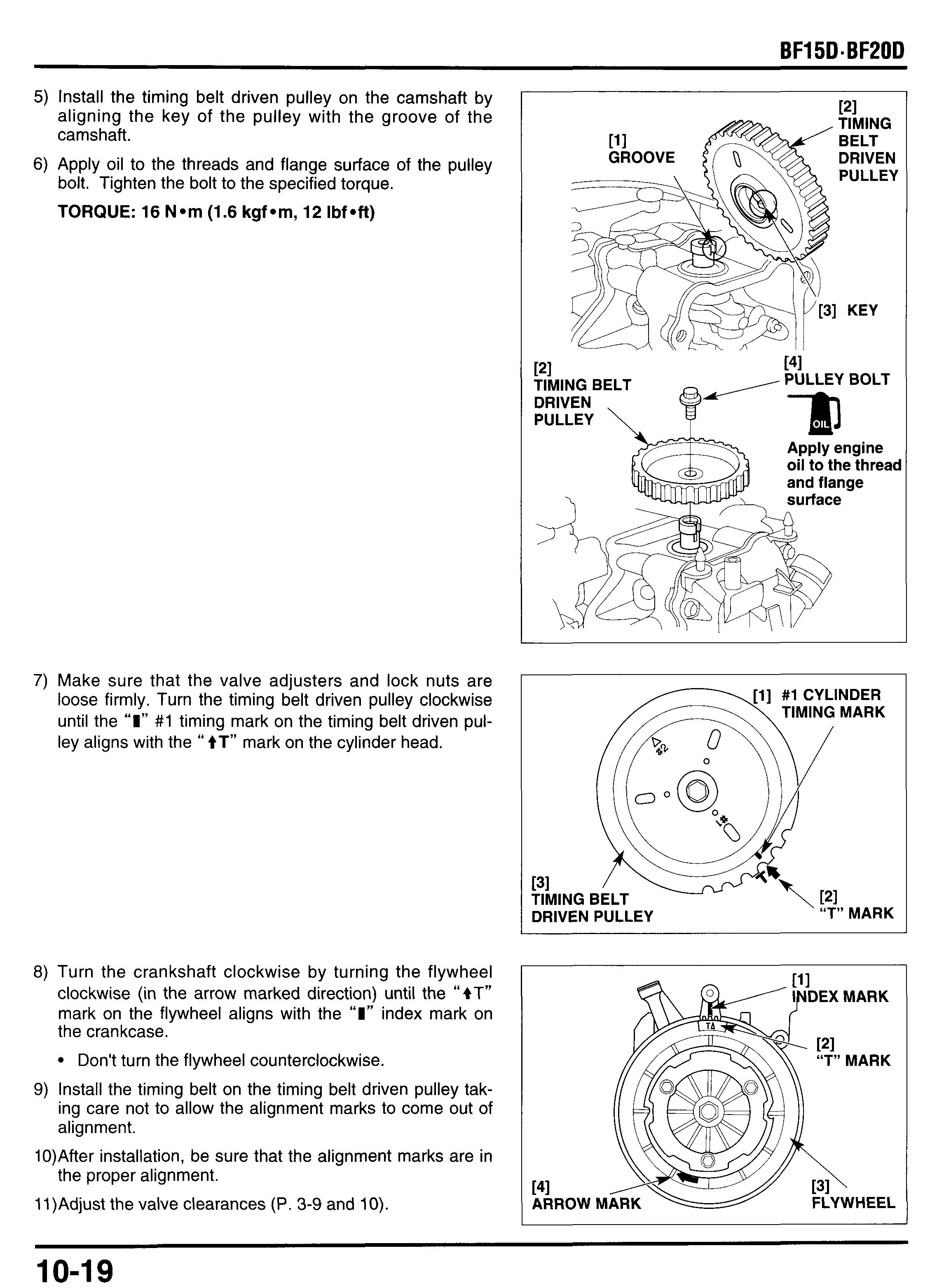
5) Install the timing belt driven pulley on the camshaft by aligning the key of the pulley with the groove of the camshaft.
6) Apply oil to the threads and flange surface of the pulley bolt. Tighten the bolt to the specified torque.
TORQUE: 16 N*m (1.6 kgf*m, 12 Ibf*ft)
7) Make sure that the valve adjusters and lock nuts are loose firmly. Turn the timing belt driven pulley clockwise until the “I” #1 timing mark on the timing belt driven pulley aligns with the “ tT” mark on the cylinder head.
8) Turn the crankshaft clockwise by turning the flywheel clockwise (in the arrow marked direction) until the “4T” mark on the flywheel aligns with the “I”index mark on the crankcase.
Don’t turn the flywheel counterclockwise.
9) Install the timing belt on the timing belt driven pulley taking care not to allow the alignment marks to come out of alignment.
10)After installation, be sure that the alignment marks are in the proper alignment.
11)Adjust the valve clearances (P. 3-9 and 10).
12)Set the cylinder head cover gasket to the cylinder head cover, then install the cylinder head cover.
13)Tighten the four head cover bolts securely.
14)Secure the throttle cable by hooking to the clamp of the cylinder head cover (tiller handle type only).
15)lnstall the spark plugs and connect the spark plug caps and thermo sensor connector.
16) Reinstall the removed parts:
- starter case B (P. 7-10).
- recoil starter (P. 7-9).
- neutral start cable (P. 7-1).
- left and right engine under covers (P. 5-2 and 3).
- engine cover.
1. THERMOSTATMATER JACKET
[13] FUSE HOLDER
[12]FUSE HOLDER BRACKET [llITHERMOSTA
a. REMOVAL
1) Remove the following:
- engine cover (P. 5-1).
- left engine under cover (P. 5-2).
- recoil starter (P. 7-2).
2) Pull off the fuse holder from the fuse holder bracket.
3) Disconnect the thermo sensor wire connector.
4) Remove the spark plug caps from the spark plugs and disconnect the ignition coil primary wires. Remove the wire band clip from the ignition coil bracket and remove the ignition coil.
5) Open the wire band clip on the clip bracket B and free the wire harness.
6) Remove the 6 x 26 mm and 6 x 14 mm flange bolts and remove the regulatorhectifier.
7) Remove the two 6 x 36 mm flange bolts and remove the thermostat cover, cover gasket and thermostat.
Remove the six 6 x 22 mm flange bolts and remove the following:
- fuse holder bracket.
- water jacket cover.
- jacket cover O-ring.
- water tube seal.
- flush valve and flush valve spring.
9)
Remove the 5 x 20 mm screw and anode. Replace the anode with new one, if it is excessively corroded.
b. INSPECTION THERMOSTAT
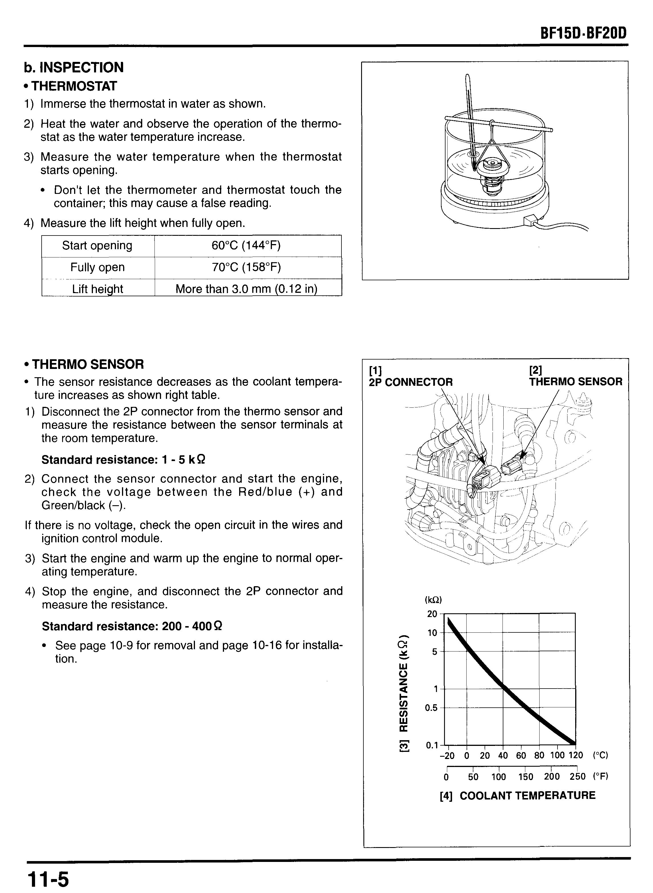
1) Immerse the thermostat in water as shown.
2) Heat the water and observe the operation of the thermostat as the water temperature increase.
3) Measure the water temperature when the thermostat starts opening.
Don't let the thermometer and thermostat touch the container; this may cause a false reading.
4) Measure the lift height when fully open.
Thermo Sensor
The sensor resistance decreases as the coolant tempera- ture increases as shown right table.
1) Disconnect the 2P connector from the thermo sensor and measure the resistance between the sensor terminals at the room temperature.
Standard resistance: 1 - 5 kR
2) Connect the sensor connector and start the engine, check the voltage between the Red/blue (+) and Greedblack (-).
If there is no voltage, check the open circuit in the wires and ignition control module.
3) Start the engine and warm up the engine to normal operating temperature.
4) Stop the engine, and disconnect the 2P connector and measure the resistance.
Standard resistance: 200 - 400 R
See page 10-9 for removal and page 10-16 for installation.
c. INSTALLATION
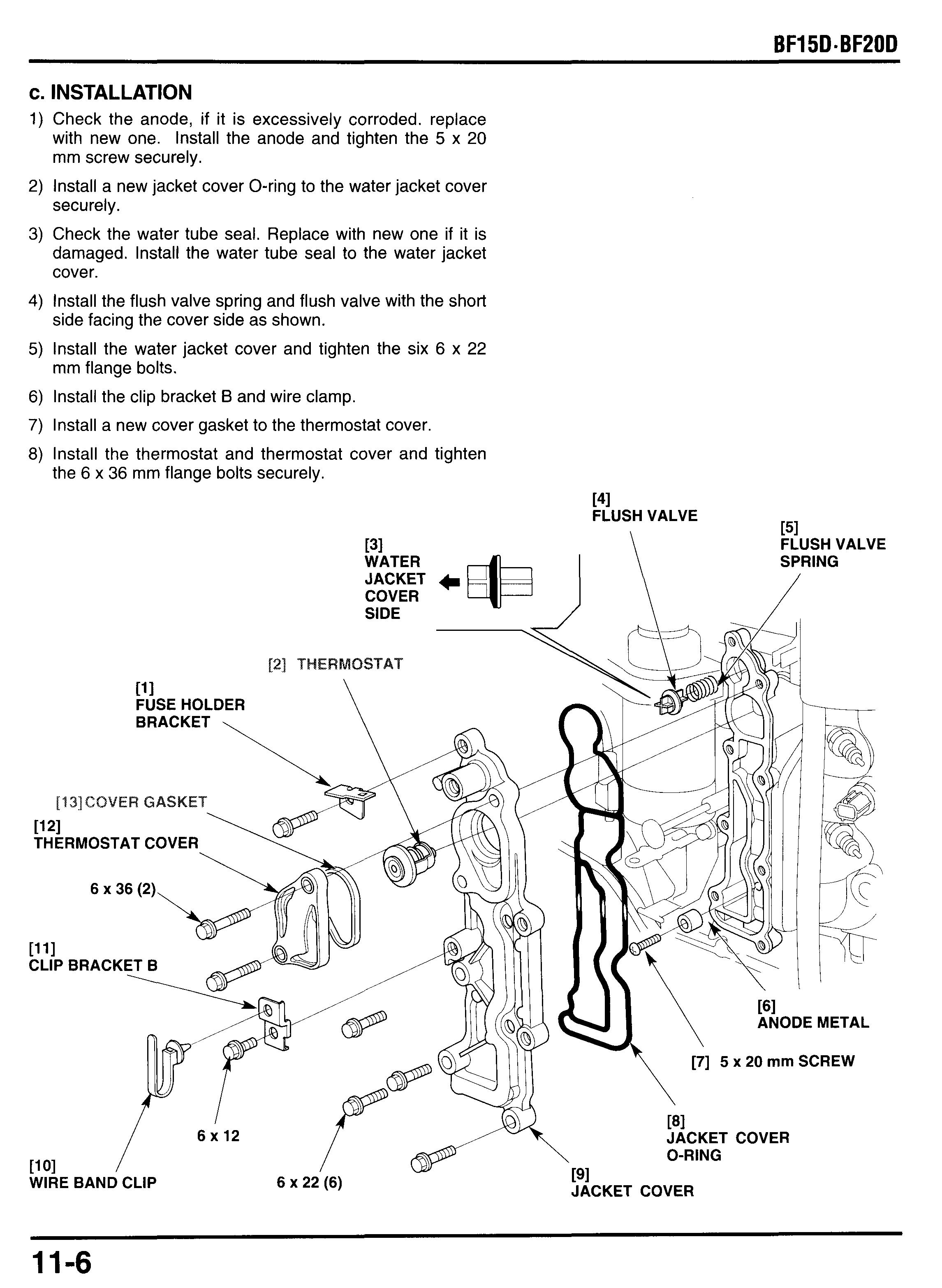
Check the anode, if it is excessively corroded. replace with new one. Install the anode and tighten the 5 x 20 mm screw securely.
Install a new jacket cover O-ring to the water jacket cover securely.
Check the water tube seal. Replace with new one if it is damaged. Install the water tube seal to the water jacket cover.
Install the flush valve spring and flush valve with the short side facing the cover side as shown.
Install the water jacket cover and tighten the six 6 x 22 mm flange bolts.
Install the clip bracket B and wire clamp.
Install a new cover gasket to the thermostat cover.
Install the thermostat and thermostat cover and tighten the 6 x 36 mm flange bolts securely.
9) Install the ignition coil to the ignition coil bracket.
10) Install the regulatorhectifier and clip brackets E and F
11)Route the wire harness and ignition coil wires and secure and tighten the 6 x 26 mm flange bolts. them with the wire band clips.
Replace the wire band with new one if it is cut.
12)Connect the thermo sensor connector and spark plug
13)Reinstall the removed parts in the reverse order of caps. removal.
2. OIL STRAINER
a. DISASSEMBLY/REASSEMBLY
Remove the engine (Section 8). Before installation check the fuel tubes for deterioration, cracks, and other damage. Replace if necessary.
'161 OIL STRAINER
INSTALLATION: Clean any dirt or foreign material from the oil strainer, and check for tears in the strainer mesh, replace if necessary.
\ 6 x 22 (2)
3. PlSTON
a. REMOVAL
1) Remove the engine (Section 8) and remove the following:
- flywheel and timing belt drive pulley (P. 9-2).
- silencer and carburetor (P.6-2)
- fuel pump and fuel filter (P. 6-16).
- cylinder head (P.11-2).
2) Remove the four 6 x 22 mm flange bolts and crankcase
3) Turn the crankshaft until the piston is at top dead center. side cover and side cover gasket.
4) Remove the connecting rod bolts and connecting rod caps.
Mark the connecting rod caps so they can be placed back in their original position.
5) Remove the pistonkonnecting rod assemblies. Mark the pistonkonnecting rod assemblies so they can be placed back in their original position.
b. DISASSEMBLY
1) Remove the piston pin clip using a log nose pliers, and remove the piston pin and connecting rod from the piston.
2) Spread each piston ring and remove it by lifting it up at a point just opposite the gap.
Take care not to damage the piston ring by spreading the ends too far.
Be careful no to damage the piston when the piston ring removal.
171 SECONDRING (combination ring)
CONNECTING ROD INSPECTION P. 11-12,18
b. INSPECTION CYLINDER
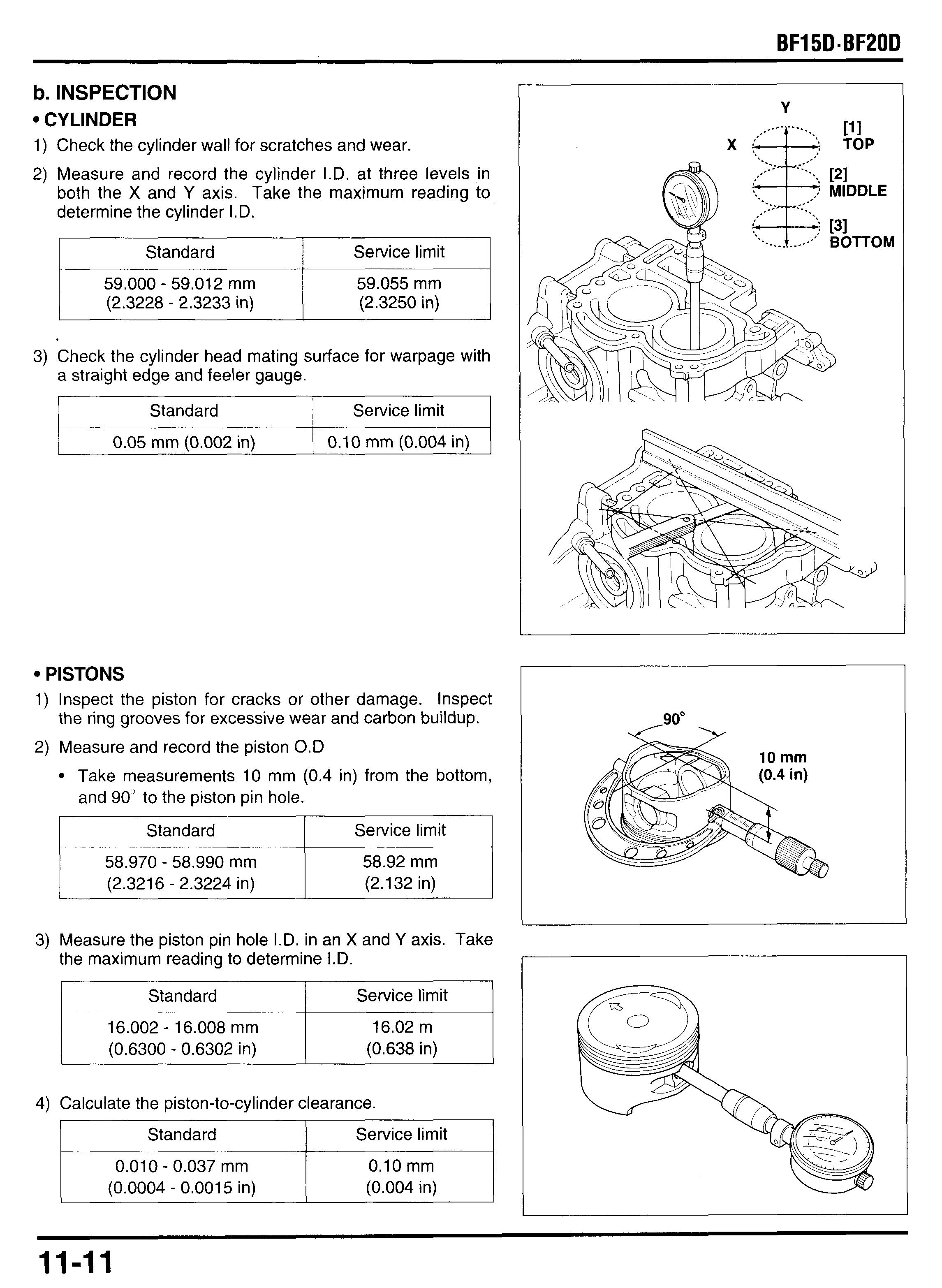
1) Check the cylinder wall for scratches and wear.
2) Measure and record the cylinder I.D. at three levels in both the X and Y axis. Take the maximum reading to determine the cylinder I.D.
3) Check the cylinder head mating surface for warpage with a straight edge and feeler gauge.
3) Measure the piston pin hole I.D. in an X and Y axis. Take the maximum reading to determine I.D.
4) Calculate the piston-to-cylinder clearance.
Piston Pins
1) Measure and record the piston pin O.D. at three position shown.
2) Calculate the piston pin-to-pistonclearance.
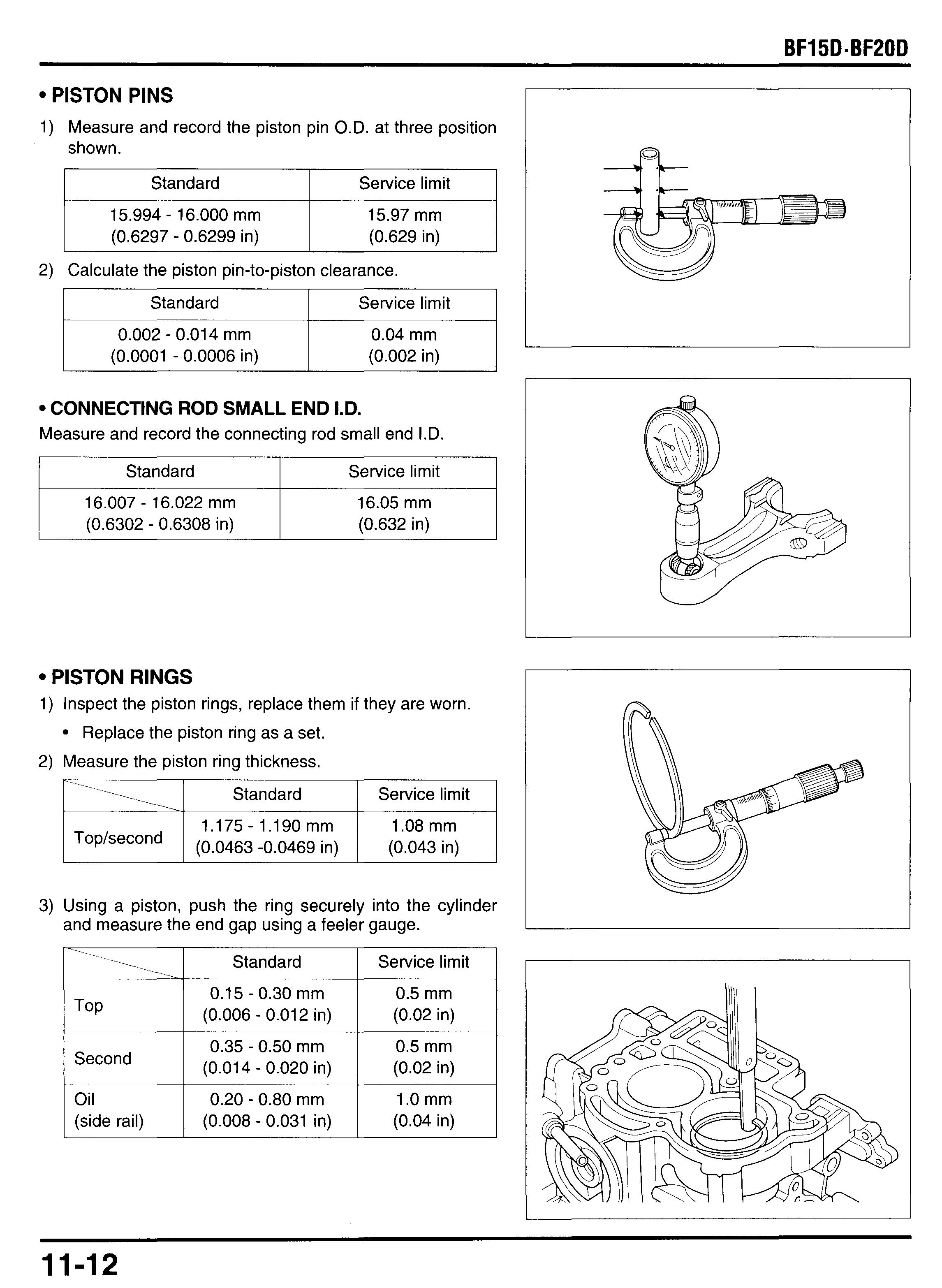
3) Using a piston, push the ring securely into the cylinder and measure the end gap using a feeler gauge.
4) Reinstall the piston rings into the piston grooves. Push in the ring until the outer surface of the piston ring is nearly flush with the piston and measure the side clearance using a feeler gauge
d. ASSEMBLY
1) Clean the piston and carefully install the piston rings. Take care not to damage the piston ring by spreading the ends too far.
Be careful no to damage the piston when the piston ring removal.
Clean carbon deposits from the piston ring grooves with a ring that will be discarded. Never use a wire brush; it will scratch the grooves.
Do not confuse the top and second rings. The top ring is chrome-coated (gray) and second not coated (black).
Install the top and second rings with the mark facing UP.
Oil ring; first install the spacer the install the side rails.
2) After installing the ring make sure that they should be rotate freely, without sticking.
3) Space the ring end gaps 120" apart and side rail end gaps about 20 mm (0.8 in) as shown.
4) Apply engine oil to the piston pin and connecting rod small end I.D. and piston pin bore.
5) Install the connecting rod to the piston with the oil groove facing the opposite side of the arrow mark on the piston head.
6) Install the piston pin.
7) Install a new piston pin clip.
Always use a new piston pin clip, never reuse used clip.
Set the piston pin clip in the groove properly. Do not align the clip's end gap with the cutout.
e. INSTALLATION
1) Apply engine oil to the piston outer surface, piston rings and cylinder wall.
2) Set the piston to a commercially available piston ring compressor. Install the pistons with the arrow mark on the piston head facing up. Take care not to damage the piston rings and cylinder wall.
4. CRANKSHAFTKYLINDER BLOCK
a. DISASSEMBLY
1) Remove the engine (Section8) and remove the following:
- flywheel and timing belt drive pulley (P. 9-2 and 10).
- silencer and carburetor (P. 6-2)
- fuel pump and fuel filter (P. 6-17).
- cylinder head (P. 10-2).
2) Turn the crankshaft until the piston is at top dead center
3) Remove the eight 6 x 28 mm flange bolts. Loosen the bolts in a crisscross pattern in 2 - 3 steps.
4) Insert a screwdriver or equivalent tool into the concave in the position shown, and lift the crankcase cover slightly. Be careful not to damage the mating surface when removing the crankcase cover.
5) Remove the crankcase cover and 8 x 14 mm dowel pins. CRANKCASE
6) Remove the four 6 x 22 mm flange bolts and crankcase S,DE COVER GASKET side cover and side cover gasket.
7) Remove the connecting rod bolts and connecting rod caps.
Mark the connecting rod caps so they can be placed back in their original position.
I Remove the piston assemblies. Mark the pistons so they can be placed back in their original position.
Remove the crankshaft from the cylinder block.
Pi Crankshaft
ROD BOLT (4)
b. INSPECTION CRANKSHAFT
1) Clean all oil from the crank pin and connecting rod big
2) Place a piece of plastigauge on the crank pin, install the end I.D. connecting rod and cap and tighten the bolts.
TORQUE: 12 N*m (1.2 kgf*m, 9 Ibf*ft)
Do not rotate the crankshaft while the plastigauge is in place.
3) Remove the connecting rod and measure the plastigauge at its widest portion.
4) Measure and record the main journal O.D.
5) Measure the crank pin journal O.D.
Connecting Rod
1) Measure the connecting rod big end I.D.
2) Install the connecting rod and connecting rod cap, and tighten the connecting rod cap bolts. Measure the connecting rod big end side clearance with the connecting rod facing up as shown using a feeler gauge.
1) Check the oil seal of the crankcase cover, replace if damaged. Remove the oil seal and discard it. Install a new oil seal securely.
2) Apply grease to the lip of the oil seal.
3) If the oil pressure switch removed, install the oil pressure switch.
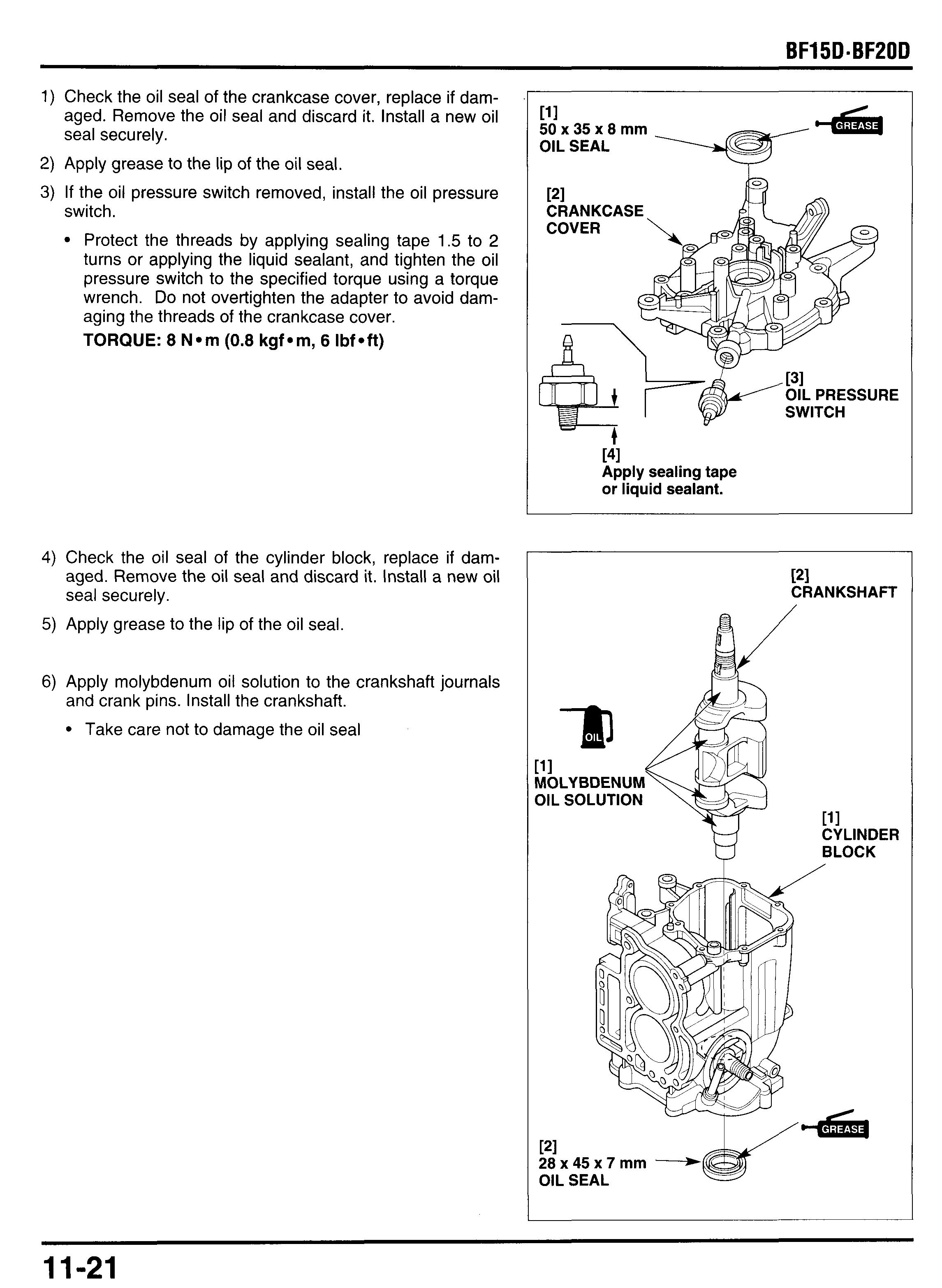
Protect the threads by applying sealing tape 1.5 to 2 turns or applying the liquid sealant, and tighten the oil pressure switch to the specified torque using a torque wrench. Do not overtighten the adapter to avoid damaging the threads of the crankcase cover.
TORQUE: 8 Nom (0.8 kgfom, 6 Ibfoft)
4) Check the oil seal of the cylinder block, replace if damaged. Remove the oil seal and discard it. Install a new oil seal securely.
5) Apply grease to the lip of the oil seal
1 50 x 35 x 8 rnrn
11
7) Set the crankshaft at T.D.C. by turning
CYLINDER HEAD SIDE
8) Clean the crankcase cover and cylinder block mating surfaces with a degreasing cleaning agent or a clean shop towel.
9) Apply liquid sealant (Three Bond 1280 or equivalent) to the position shown on the crankcase cover. Apply a bead about 1.5 mm (0.06 in) in diameter. Assemble the crankcase side cover within 3 minutes after application of the liquid sealant. Wait for 20 minutes after assembly. Do not add oil or start the engine during this period.
[l] Apply a bead about 1.O mm (0.04 in) in diameter.
Don't apply this area.
10)Make sure that the 14 x 20 mm dowel pin is in the place.
1l)lnstall the 8 x 14 mm and crankcase cover.
12)Apply oil to the threads and flange surfaces of the 6 x 28 mm flange bolts and tighten them to the specified torque.
Tighten the bolts in the numbered sequence shown in 2 - 3 steps.
TORQUE: 14 Nmm (1.4 kgfmm, 10 Ibfmft)
13)Apply engine oil to the piston outer surface, piston rings and cylinder wall.
14 Set the piston to a commercially available piston ring compressor. Install the pistons with the arrow mark on the piston head facing up.
Take care not to damage the piston rings and cylinder wall.
PI


