4 minute read
15. TILLER HANDLE


1. TILLER HANDLE
2. TILLER HANDLE BRACKET
3. THROTTLE GRIP
4. STARTER SWITCH
5. EMARGENCY STOP SWITCH
1. TILLER HANDLE
a. REMOVAL
1) Remove the following:
- engine cover (P. 5-1).
- left engine under cover (P. 5-2).
2) Lift the starter case B slightly, and disconnect the tube from the starter case B at the carburetor side.
3) Remove the 6 x 14 mm flange bolt and throttle cable stay. Disconnect the throttle cable pivot linkage from the carburetor throttle lever.
4) Type without electric starter: Remove the emergency stop switch wire connectors from connector bracket A and disconnect them.
Type with electric starter: Remove the starter switch and emergency stop switch wire connectors from the connector bracket A and disconnect them.
131 STARTER SWITCH WIRE (Type with electric starter)
5) Remove the charge connector from the stay.
6) Remove the shift lever pivot bolt, 10 mm wave washer, two 9 mm plain washers, 6 mm plain washer.
LINK ROD
7) Disconnect the link rod from the shift lever then remove the shift lever. assembly.
8) Pull off the oil case grommet from the oil case.
b. INSTALLATIO
1) Set the tiller handle assembly to the oil case and loosely
2) Pass the throttle cable, switch wires through the oil case install the 10 x 55 mm washer bolts. hole
Route the wires and throttle cable as shown.
3) Set the oil case grommet securely.
4) Apply grease to the link rod and connect to the shift lever.
5) Apply grease to the shift lever pivot bolt and install the shift lever to the tiller handle with the shift lever pivot bolt, 10 mm wave washer, two 9 mm plain washers and 6 mm plain washer.
6) Tighten the 10 x 55 mm washer bolts to the specified torque.
TORQUE: 33 Nom (3.4 kgfom, 25 Ibfoft)
7)
2. TILLER HANDLE BRACKET
a. REMOVAL
1) Remove the 8 mm self-locking nut and 8 mm washer. Remove the handle pivot bolt and separate the tiller handle bracket.
2) Remove the spiral protector, then pull out the throttle cable and switch wires tacking care not to damage the switch wires.
3) Remove the oil case grommet.
4) Remove the tiller handle bracket.
b. INSTALLATION
1) Install the oil case grommet to the tiller handle bracket, then install the switch wires and throttle cable through the oil case grommet.
2) Set the tiller handle bracket to the tiller handle.
3) Install the handle pivot bolt and 8 mm washer, and tighten the 8 mm self-locking nut to the specified torque.
TORQUE: 8 N*m (0.8 kgfom, 6 Ibf*ft)
Route the throttle cable and switch wires over the pivot bolt as shown.
4) Lap the spiral protector around the throttle cable and switch wires as shown.
3. THROTTLE GRIP
a. DISASSEMBLY
1) Remove the grip rubber, then remove the 6 x 12 mm flange bolt.
2) Remove the throttle friction grip and throttle friction pad
3) Remove the throttle grip pipe by turning counterclockwise viewed from grip end and remove the throttle friction block
THROTTLE
FRICTION GRIP THROTTLE FRICTION PAD FRICTION BLOCK GRIP
4) Remove the throttle cable pin from the cable pivot.
5) Loosen the lock nut and remove the throttle cable pivot.
6) Type with electric starter: Remove the four 4 x 10 mm self-tapping screws and lift up the starter switch housing with the starter switch attached (P. 15-12).
TORQUE: 1.5 N*m (0.15 kgf*m, 1.1 Ibf*ft)
3) Type with electric starter: Install the starter switch housing assembly to the tiller handle and tighten the four 4 x 10 mm self-tapping screws.
4) Loosen the lock nut fully and screw the cable pivot as shown.
Make sure that the bent end (motor side) of the throttle cable facing as shown.
5) Tighten the lock nut securely. Apply grease to the sliding surfaces of the cable pivot.
5-7mm / [11 LOCK NUT CABLE PIVOT
6) Apply grease to the throttle grip installation surface of the tiller handle and friction block. Install the friction block by aligning the grooves of the throttle friction block with the bosses of the tiller handle as shown.
7) Install the throttle cable pin on the cable pivot with the projected length at both ends of the pin equal as shown.
8 mm (0.31 in)
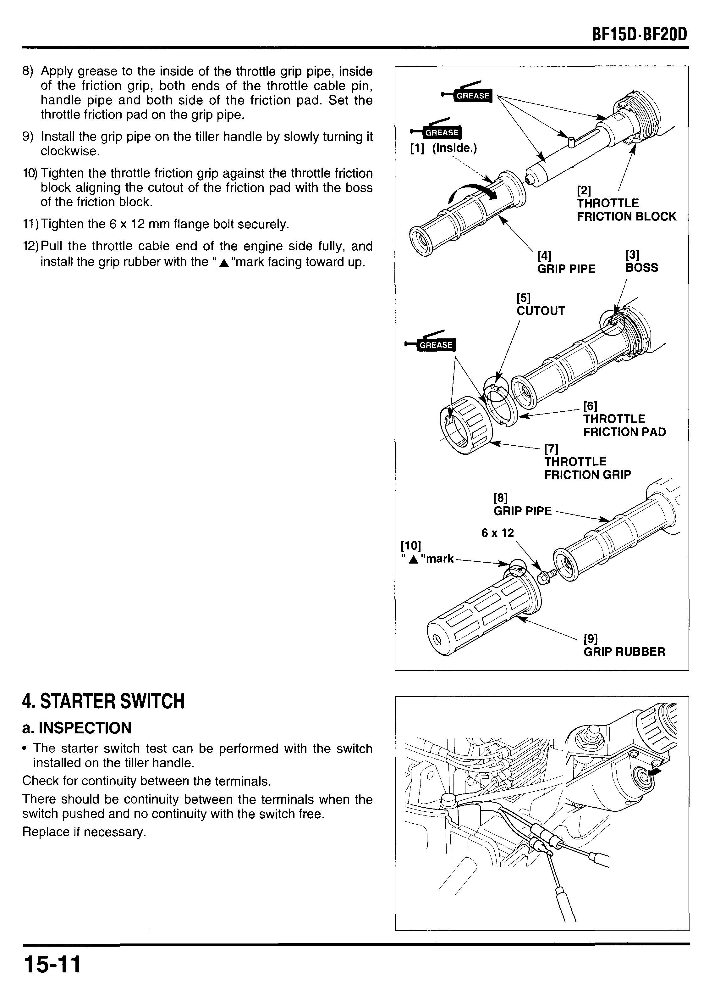
8) Apply grease to the inside of the throttle grip pipe, inside of the friction grip, both ends of the throttle cable pin, handle pipe and both side of the friction pad. Set the throttle friction pad on the grip pipe.
9) Install the grip pipe on the tiller handle by slowly turning it clockwise.
10) Tighten the throttle friction grip against the throttle friction block aligning the cutout of the friction pad with the boss of the friction block.
11)Tighten the 6 x 12 mm flange bolt securely.
12)Pull the throttle cable end of the engine side fully, and install the grip rubber with the " A "mark facing toward up.
4. STARTER SWITCH
a. INSPECTION
The starter switch test can be performed with the switch installed on the tiller handle.
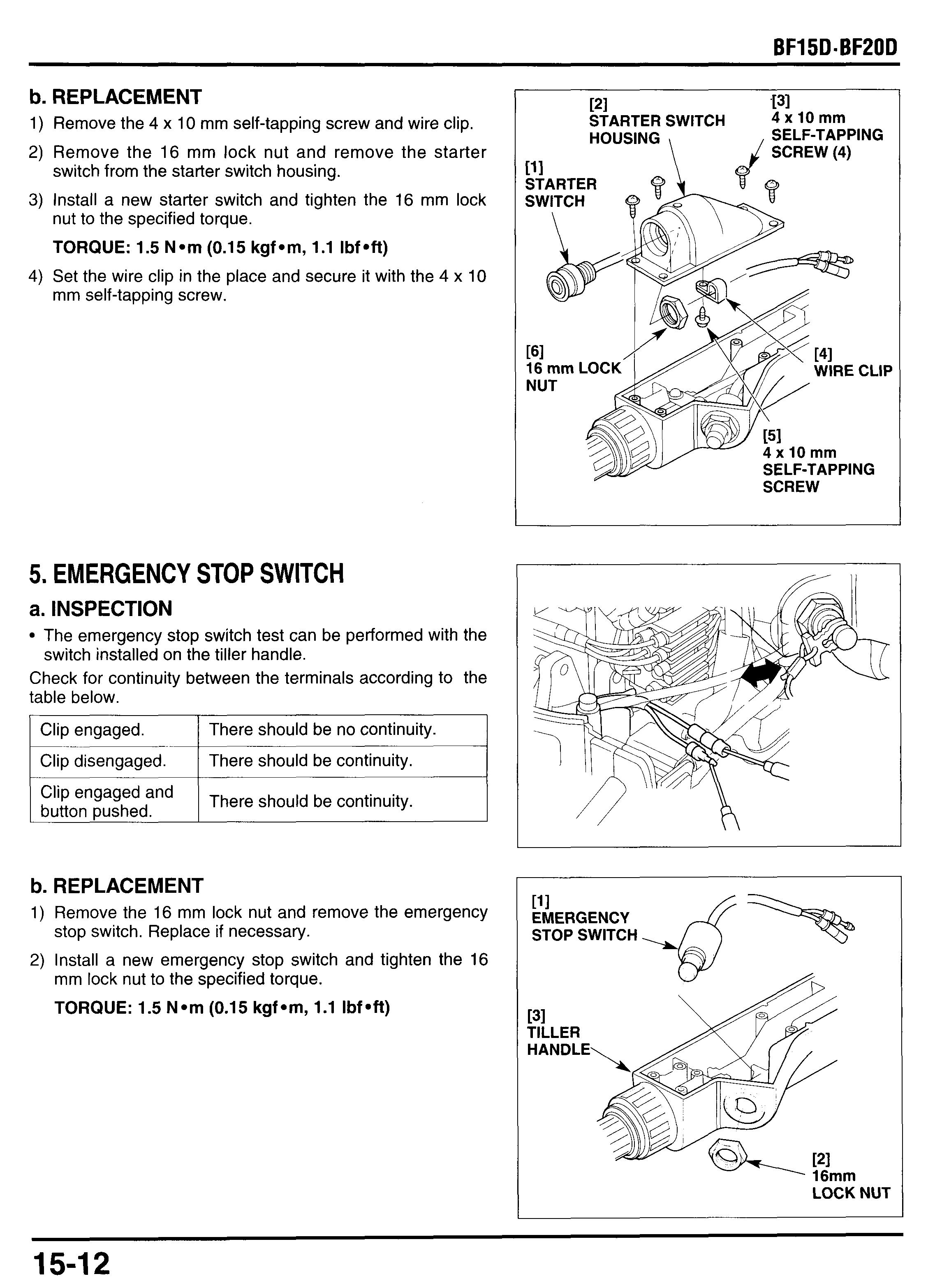
b. REPLACEMENT
1) Remove the 4 x 10 mrn self-tapping screw and wire clip.
2) Remove the 16 mrn lock nut and remove the starter
3) Install a new starter switch and tighten the 16 rnrn lock switch from the starter switch housing. nut to the specified torque.
TORQUE: 1.5 Narn (0.15 kgfam, 1.1 Ibf aft) mm self-tapping screw.
4) Set the wire clip in the place and secure it with the 4 x 10
5. EMERGENCY STOP SWITCH
a. INSPECTION
The emergency stop switch test can be performed with the switch installed on the tiller handle.
Check for continuity between the terminals according to the table below.
I Clip engaged. I There should be no continuity. I
I Clip disengaged. I There should be continuity. I c-- I
‘lip engaged and button pushed.
b. REPLACEMENT
There should be continuity.
1) Remove the 16 mm lock nut and remove the emergency
2) Install a new emergency stop switch and tighten the 16 stop switch. Replace if necessary. mm lock nut to the specified torque.
TORQUE: 1.5 Narn (0.1 5 kgf am, 1.1 Ibf eft)


