4 minute read
ENGINE REMOVAUINSTALLATION


1. ENGINE REMOVAL
1. ENGINE REMOVAL
1) Remove the following:
- engine cover (P. 5-1).
- left engine under cover (P. 5-2).
- right engine under cover (P. 5-3).
- recoil starter (P. 7-1) and neutral start cable (P. 7-9).
- remote control cables (P. 14-2).
- remote control box wire harness (P. 14-3).
2) Drain the engine oil to a suitable container (P. 3-3).
2. ENGINE INSTALLATION
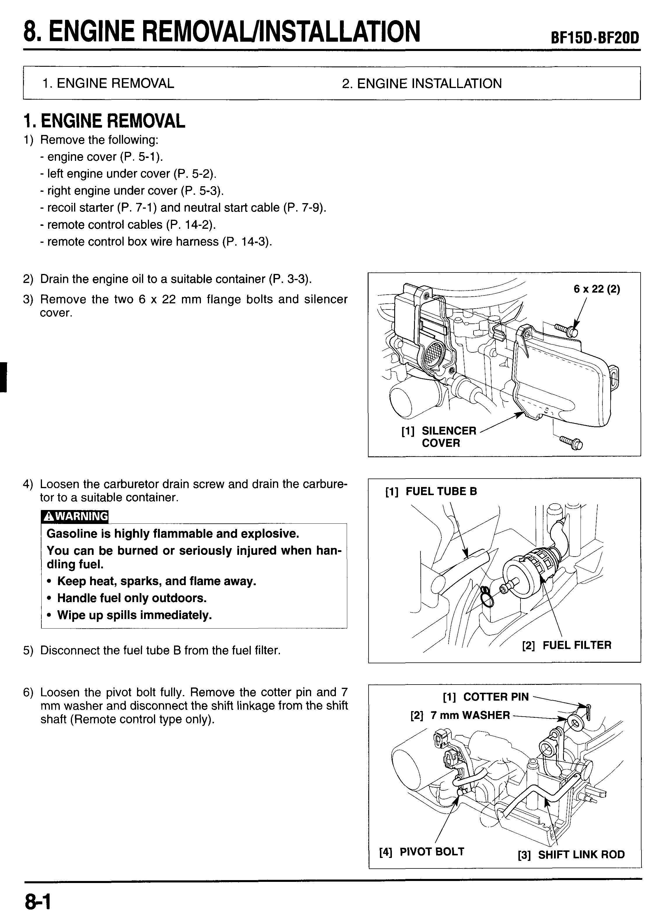
3) Remove the two 6 x 22 mm flange bolts and silencer cover.
4) Loosen the carburetor drain screw and drain the carburetor to a suitable container.
Gasoline is highly flammable and explosive. You can be burned or seriously injured when handling fuel.
Keep heat, sparks, and flame away. Handle fuel only outdoors.
Wipe up spills immediately.
5) Disconnect the fuel tube B from the fuel filter.
6) Loosen the pivot bolt fully. Remove the cotter pin and 7 mm washer and disconnect the shift linkage from the shift shaft (Remote control type only).
7) Disconnect the wire connector from the oil pressure switch.
8) Remove the wires and connectors from the holder of the starter case B.
Connectors And Wires
9) Disconnect the SE thermal valve wire connectors (Type
Refer to page 2-36 for connector location. with electric starter).
1O)Pull up the starter case B slightly and disconnect the drain tube from the starter case B. Remove the 6 x 14 mm flange bolt and throttle cable stay, then disconnect the linkage pivot of the throttle cable from the carburetor throttle lever (Tiller handle type).
11)Unfasten the harness band clip and free the wires (neutral switch wire and/or indicator wire).
12)Remove the two 6 x 25 mm flange bolts, ignition control
13)Pull out the following connectors ,;om the connector bracket A, and disconnect the connectors: r11
- charge coil wire.
- exciter coil wire.
- pulse generator coil wire.
- starter magnetic switch wire.
Refer to page 2-31 (Tiller handle type) or 2-33 (Remote control type) for connector location.
14)Unfasten the wire band at the starter magnetic switch and disconnect the starter cable from the starter magnetic switch by removing the 6 mm self-locking nut(Type with electric starter).
15)Remove the 6 x 12 mm flange bolts and disconnect the battery ground terminal (Type with electric starter) and engine ground terminal.
6 mm SELFLOCKING NUT the three 6 x 14 mm flanne b
18)Disconnect the spark plug caps and thermo sensor wire connector.
19)Unfasten the harness band clip on the clip bracket B and free the wire harness.
20)Remove the two 6 x 26 mm flange bolts mounting the regulatorhectifier.
21)Remove the 6 x 12 mm flange bolt and disconnect the regulatorhectifier ground terminal (Type with electric starter).
22)Remove the two 6 x 14 mm flange bolts and ignition coil with the bracket attached.
23)Remove the exhaust chamber cover (P. 4-31).
24)Remove the nine 8 x 35 mm engine mounting bolts.
[l] LEFT ENGINE UNDER COVER SIDE \\
25) Pull out the drain tubes from the oil case and remove the
26)Remove the two 6 x 10 mm dowel pins and oil case gasengine from the oil case ket.
2. ENGINE INSTALLATION
1) Install the two 6 x 10 mm dowel pins and a new oil case gasket.
Replace the oil case gasket with new one, when reassembling.
2) Apply marine grease to the spline of the vertical shaft, and install the engine by aligning the vertical shaft and crankshaft.
3) Tighten the engine mount bolts to the specified torque. Tighten the bolt in the numbered sequence as shown ' and 2 - 3 steps.
TORQUE: 24 N*m (2.4 kgf*m, 17 Ibf*ft)
4) Install the exhaust chamber (P. 4-31).
5) Install the following:
- ignition coil.
- regulatorhectifier.
- clip plate and clip bracket.
- regulatorhectifier ground terminal.
6) Route the wires and connect the spark plug caps, and thermo sensor connector. Secure the wires with the wire band.
Replace the wire band with new one, if it is cut.
7) Install the ignition control module plate with the connector bracket A attached and secure the three 6 x 14 mm flange bolts.
8) Connect the starter cable to the starter magnetic switch and tighten the 6 mm self-locking nut to the specified torque.
TORQUE: 5.5 N*m (0.55 kgfom, 4.0 Ibf*ft)
9) Tighten the 6 x 12 mm flange bolts to the ground termi- nals:
- battery ground terminal.
- engine ground terminal
10)Secure the starter cable with the wire band as shown. Replace the wire bands with new ones if they are cut.
11)Set the fuse holder to the holder plate.
12)Connect the wire connectors and set them to the connector bracket A.
Refer to page 2-31 (Tiller handle type) or 2-33 (Remote control type) for connector location.
Set the main wire harness by aligning the white tape of the main wire harness with the edge of the connector bracket A.
13)lnstall the ignition control module and bracket using the two 6 x 25 mm flange bolts.
14)Secure the indicator wire (Tiller handle type) and neutral switch wire (Type with electric starter) with the harness band clip.
Replace the wire bands with new ones if they are cut.
Clamp at the white tape section of the wire(s).
15)Apply grease to the pivot of the throttle lever and connect the throttle cable linkage pivot to the carburetor throttle lever.
16)Place the throttle cable holder by aligning the flange to the space of the lib and mounting boss, and tighten the 6 x 14 mm flange bolt.
17)Set the starter case in the place and connect the drain tube to the starter case.
18)Connect the SE thermal valve wire connectors (Type with
19) Set the connectors and wires to the holders of the starter electric starter). case 6.
Refer to page 2-36 for connector location.
[l]CONNECTORS AND WIRES
20)Connect the wire terminal to the oil pressure switch.
2l)lnstall the shift link rod to the shift shaft and install the 6 mm plain washer to the shift link rod and secure it with a new 2 mm cotter pin.
Replace the 2 mm cotter pin with a new one, when removed.
22)Connect the fuel filter to the fuel tube.
23)lnstall the silencer cover and insert the tube end to the recess on the oil case as shown.
24)Hook the fuel tube to the hook of the silencer cover.
25)Reinstall the removed parts in the reverse order of removal.
- recoil starter (P. 7-1) and neutral start cable (P. 7-9).
- remote control cable (P. 14-2).
- left engine under cover (P. 5-2).
- right engine under cover (P. 5-3).
- engine cover (P. 5-1).
26)After installation check following and adjust if necessary.
- throttle cable (P. 3-13).
- neutral start cable (P. 7-2).


