28 minute read
4.PROPELLEWGEAR CASEEXTENSION CASE BF15D.BFZoD


ADJUSTING NUT ADJUSTMENT: P. 4-11 Of
2. EXTENSION SEPARATOR
a. DISASSEMBLY/REASSEMBLY UL Type
131
30 mm INTERNAL ClRCLlP
[2120mm WASHER
111
WATER PUMP HOUSING GROMMET
[51 EXTENSION SEPARATOR
3. WATER PUMP
a. DISASSEMBLY/REASSEMBLY UL Type
VERTICAL SHAFT BUSHING
ASSEMBLY: P. 4-14 Of and 14 of the base shop manual O-RING
REASSEMBLY: P. 4-21
I’ shop manual
171 through 4-26 of the base
WATER PUMP HOUSING GROMMET
I 1. STARTER CASE B I 11
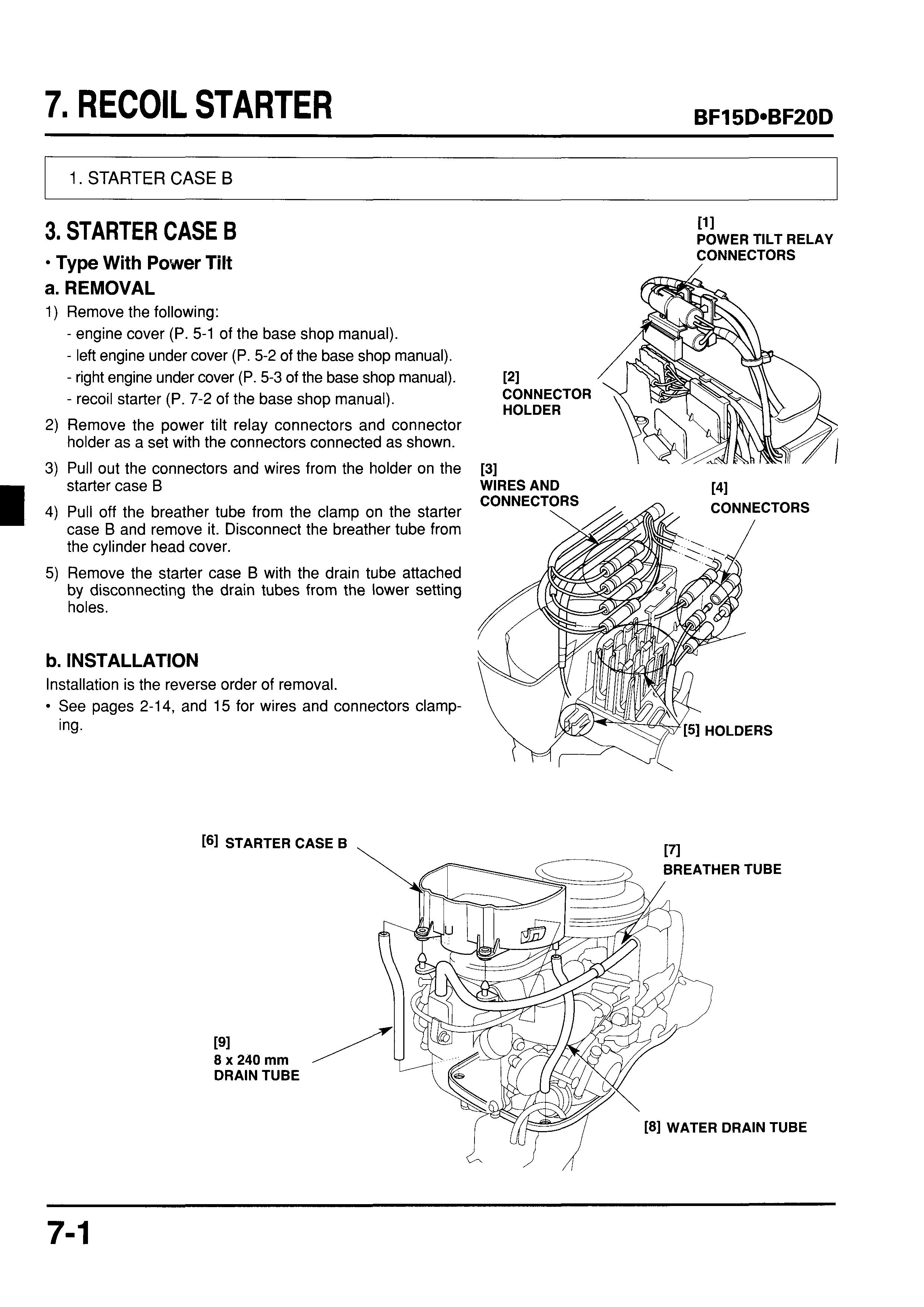
3. STARTER CASE B
CONNECTORS Type With Power Tilt
a. REMOVAL
1) Remove the following:
- engine cover (P. 5-1 of the base shop manual).
- left engine under cover (P. 5-2 of the base shop manual).
- right engine under cover (P. 5-3 of the base shop manual).
- recoil starter (P. 7-2 of the base shop manual).
2) Remove the power tilt relay connectors and connector holder as a set with the connectors connected as shown.
3) Pull out the connectors and wires from the holder on the starter case B
4) Pull off the breather tube from the clamp on the starter case B and remove it. Disconnect the breather tube from the cylinder head cover.
5) Remove the starter case B with the drain tube attached by disconnecting the drain tubes from the lower setting holes.
b. INSTALLATION
Installation is the reverse order of removal.
See pages 2-14, and 15 for wires and connectors clamping.
1. STERN BRACKET
2. SWIVEL CASE
ASSEMBLY PI 7/8-14UNF SELF-LOCKING NUT Do not reuse. Tighten to 40 N m (4.1 kgfom, 30 Ibfoft) then turn back 1/2 turn.
[41 8 mm SELF-LOCKING NUT 21 N-m (2.1 kgf-m, 15 Ibf-ft)
4. POWER
1. STERN BRACKET
Gas Assisted Tilt Disassembly
Remove the engine (see section 8 of the base shop manual), then remove the following:
- oil case (P. 12-2).
- friction adjusting lever (P. 12-4).
- mount frame (P. 12-6).
Move the tilt lever to free position to release the gas assisted damper.
Remove the adjusting rod.
Remove the tilting bolt cap and loosen the 7/8-14UNF self-locking nut, then remove the 8 mm self-locking nut, 8 mm plain washer and 8 x 203 mm hex. bolt.
Remove the 7/8-14UNF self-locking nut and discard it. Replace the self-locking nut with new one when reassembly.
Remove the left stern bracket, lower cylinder collar and 22 mm wave washer.
Remove the tilting shaft, 22 mm wave washer, carrying handle and right stern bracket.
SWIVEL CASE
DISASSEMBLY: P. 12-11
REASSEMBLY: P. 12-12 necessary.
Remove the swivel case and lower cylinder bushings if
b. REASSEMBLY
1)Apply marine grease to new swivel case bushings and install them to the swivel case.
2) Apply marine grease to new lower cylinder bushings and lower cylinder collar, then install them to the gas assisted dumper lower mount.
3)Apply marine grease to the threads of the tilting shaft, mounting hole and wave washers.
4) Install the right stern bracket, carrying handle,and 22 mm wave washer, and install the tilting bolt.
5) Install the 8 x 203 mrn hex. bolt.
4
/ CARRYING HANDLE
LOWER CYLINDER / Y
6) Apply grease to the 22 mm wave washer and install the wave washer and right stern bracket.
Loosely install a new 7/8-14UNF self-locking nut.
Install the 8 mm washer and 8 mm self-locking nut. Tighten the 8 mm self-locking nut to the specified torque.
TORQUE: 21 N em (2.1 kgf em, 15 Ibf eft)
Tighten the 7/8-14UNF self-locking nut to 40 N-m (4.1 kgf m, 30 Ibf eft) then loosen 1/2 turn.
10) Install the adjusting rod and tilting bolt caps.
1l)lnstall the anode and tighten the 6 x 12 mm flange bolt securely if the anode removed.
12)Move the tilt lever to tilt position and make sure that the swivel case moves free.
13) Install the removed parts in the reverse order of removal.
POWER TILT a DISASSEMBLY
1) Remove the power tilt motor wire from the motor:
Open the wire bands.
Open the wire band clips.
Remove the spiral protectors.
Remove the corrugated protector (Tiller handle type).
Remove the engine (see Section 8) , then remove the following:
- oil case (P. 12-1).
- friction adjusting lever (P. 12-3).
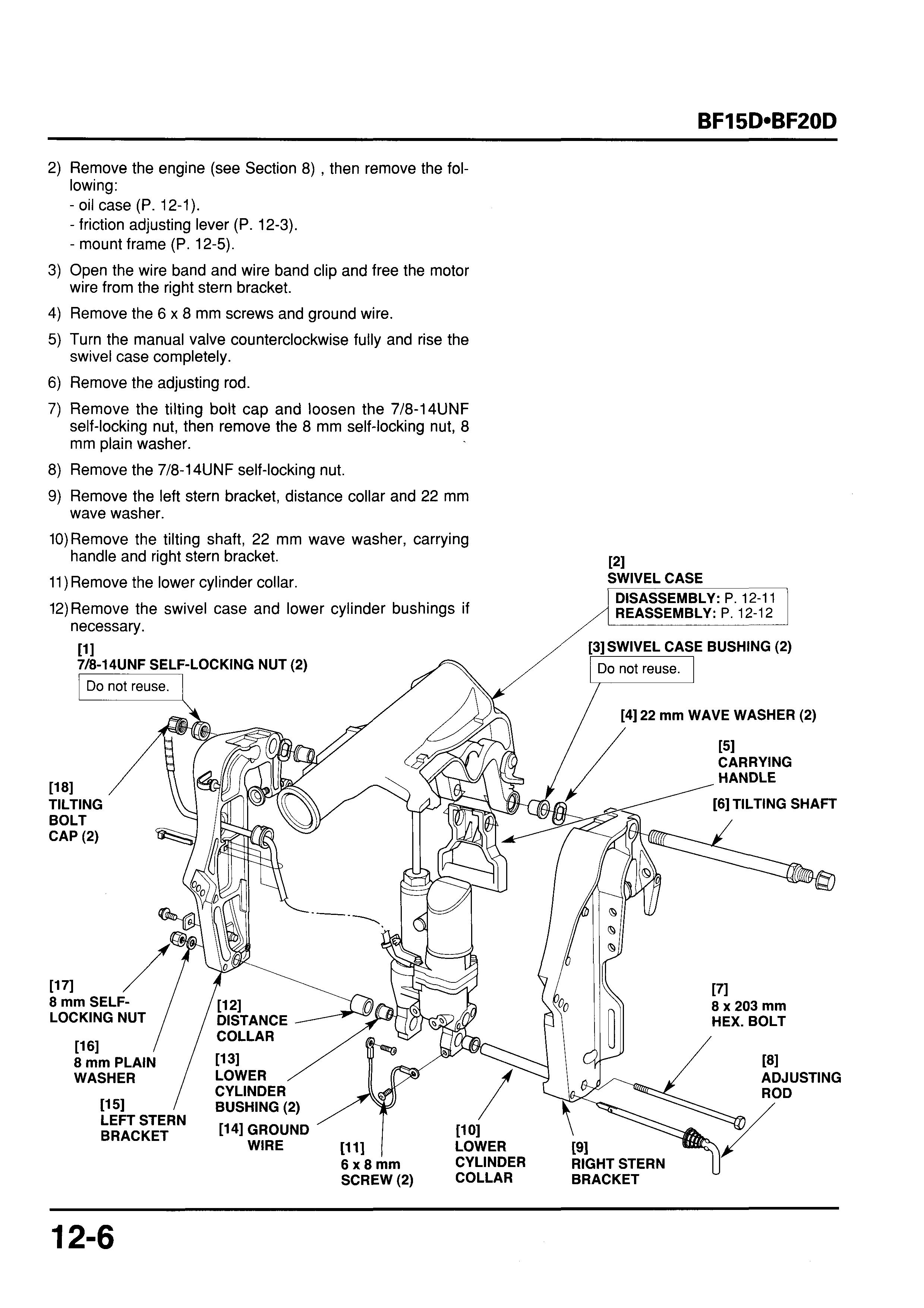
- mount frame (P.12-5).
Open the wire band and wire band clip and free the motor wire from the right stern bracket.
Remove the 6 x 8 mm screws and ground wire.
Turn the manual valve counterclockwise fully and rise the swivel case completely.
Remove the adjusting rod.
Remove the tilting bolt cap and loosen the 7/8-14UNF self-locking nut, then remove the 8 mm self-locking nut, 8 mm plain washer.
Remove the 7/8-14UNF self-locking nut.
Remove the left stern bracket, distance collar and 22 mm wave washer.
10)Remove the tilting shaft, 22 mm wave washer, carrying handle and right stern bracket.
11)Remove the lower cylinder collar.
12)Remove the swivel case and lower cylinder bushings if
b. REASSEMBLY
1)Apply marine grease to new swivel case bushings and install them to the swivel case.
2) Apply marine grease to new lower cylinder bushings and lower cylinder collar, then install them to the gas assisted dumper lower mount.
3)Apply marine grease to the threads of the tilting shaft, mounting hole and wave washers.
4) Install the right stern bracket, carrying handle,and 22 mm wave washer, and install the tilting bolt.
5) Install the 8 x 203 mm hex. bolt.
6) Set the motor wire grommet to the motor wire and install them to the left stern bracket by aligning the boss of the grommet with the groove of the left stern bracket
7) Apply grease to the 22 mm wave washer and distance collar, then install the wave washer, distance collar and right stern bracket.
8) Loosely install a new 7/8-14UNF self-locking nut.
9) Install the 8 mm washer and 8 mm self-locking nut. Tighten the 8 rnm self-locking nut to the specified torque.
TORQUE: 21 N*m (2.1 kgf-m, 15 Ibf-ft)
10)Tighten the 7/8-14UNF self-locking nut to 40 N*m (4.1 kgf m, 30 Ibf eft) then loosen 1/2 turn.
1l)lnstall the adjusting rod and tilting bolt caps.
12)lnstall the anode and tighten the 6 x 12 mm flange bolt
13)Make sure that the swivel case moves free. securely if the anode removed.
151
718-14UNF
SELF-LOCKING NUT (2)
14)Secure the power tilt motor wire with the wire band and wire band clip to the left stern bracket as shown. If the wire band or wire band clip cut, replace with new one. After securing the wire, cut the end as projected length shown.
131 WIRE BAND CLIP
PI WHITE TAPE
Clamp the center of the white tape position of the motor wire.
[6]POWER TILT MOTOR WIRE switch wires with the corrugated protector as shown. --.
ENGINE SIDE + 121
111 5 mm (0.2in) MAX.
PI 5 mm (0.2in) _MAX.
\\
141 WHITE TAPE
Clamp
[5]POWER TILT SWITCH WIRE (Tiller handle type) /
[3] WIRE BAND CLIP \
[61CORRUGATED ,, PROTECTOR
Align the center of the corrugated protector with the center of the connector bracket as shown.
WHITE TAPE
Clam the center of the white taDe Dosi- POWER TILT tion of the motor wire and powe; tilt'switch MOTOR WIRE / I wire. /
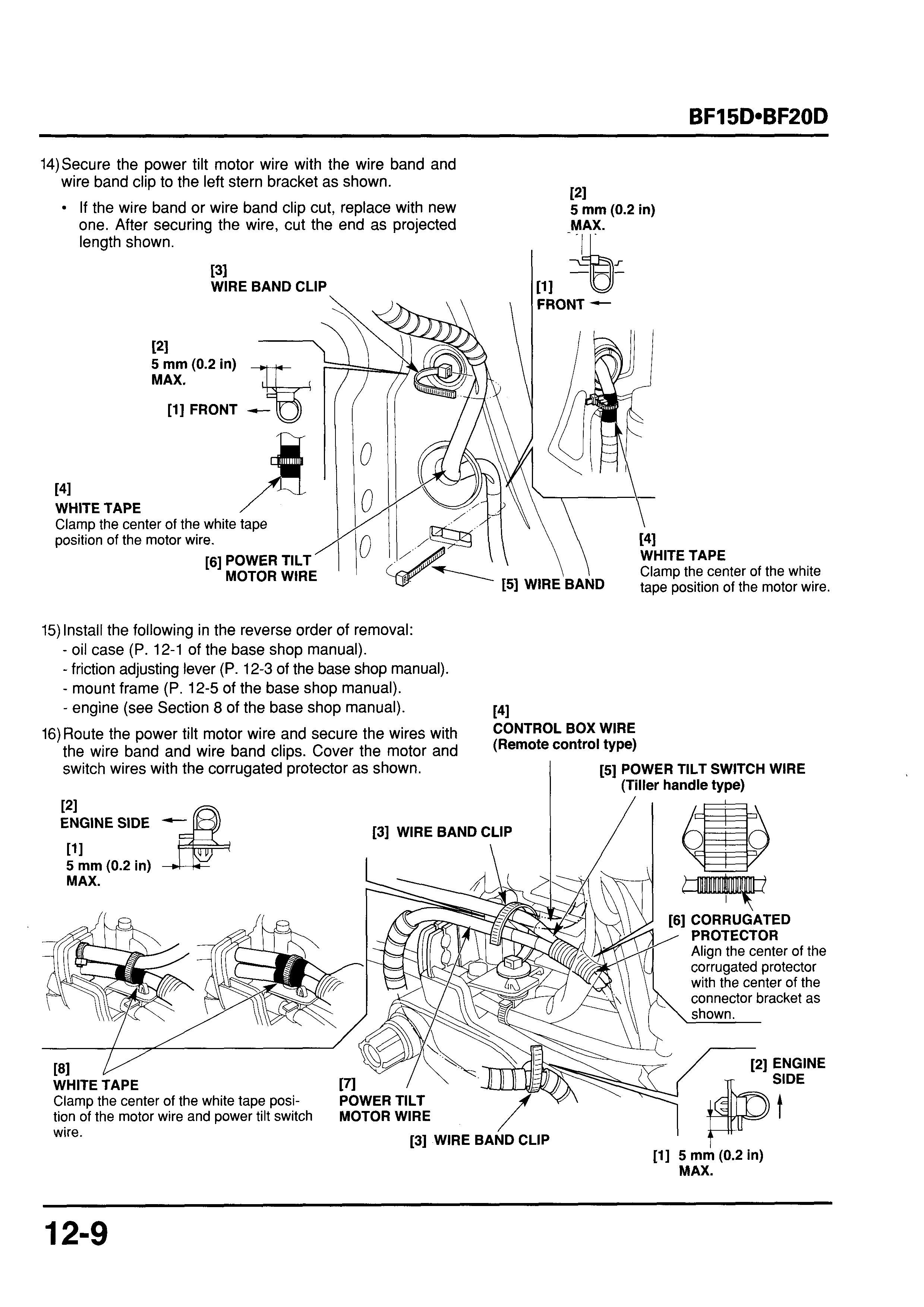
[3] WIRE BAND CLIP
[l] 5 mm (0.2in) MAX.
16)Route the power tilt motor wire along the main wire harness as shown and wrap the wires with the upper and lower spiral protectors as shown.
17)Secure the wires with the wire band clips.
If the wire band clip cut, replace with new one. After securing the wire, cut the end as projected length
[2] WIRE BAND CLIP (4)
131 ABOUT 15 mm (0.6in)
181 MAIN
11 1 POWER TILT
141 ENGINE SIDE - -MOTOR WIRE
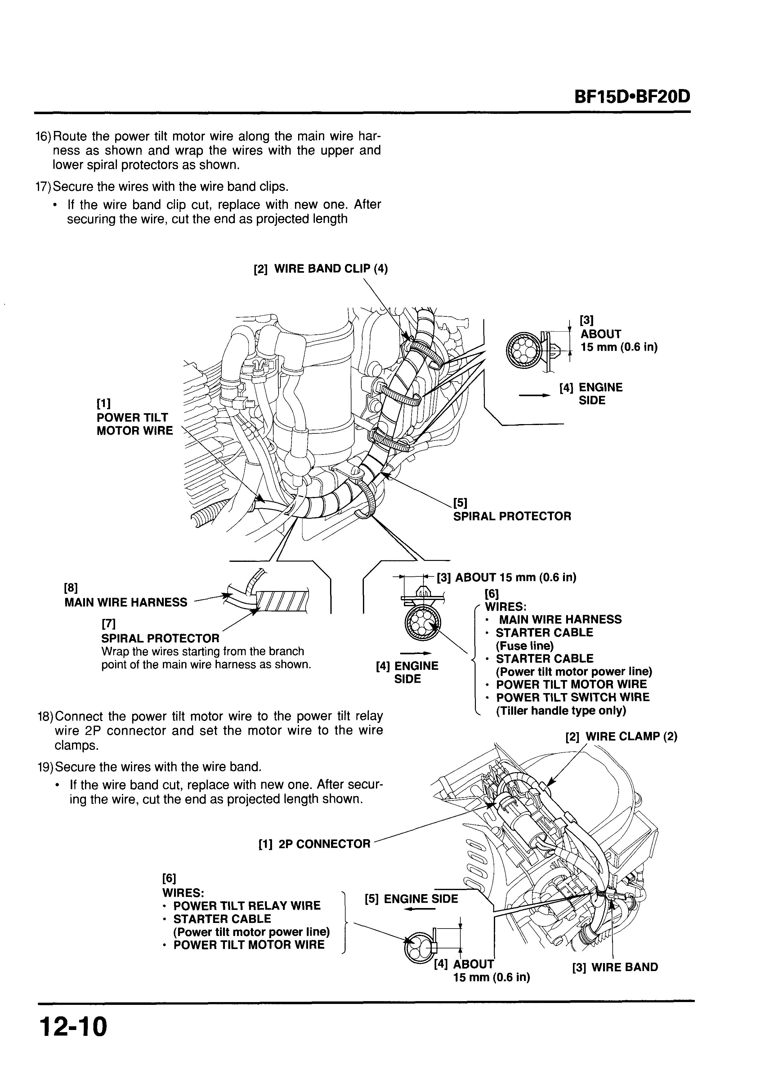
WIRE HARNESS
[71 SPIRAL PROTECTOR
Wrap the wires starting from the branch point of the main wire harness as shown.
[4]ENGINE SIDE
18)Connect the power tilt motor wire to the power tilt relay 'wire 2P connector and set the motor wire to the wire clamps.
19)Secure the wires with the wire band.
If the wire band cut, replace with new one. After securing the wire, cut the end as projected length shown.
[l] 2P CONNECTOR
SPIRAL PROTECTOR
ABOUT 15 mm (0.6in)
[GI ' WIRES:
- MAIN WIRE HARNESS
* STARTER CABLE
(Fuse line)
* STARTER CABLE
(Power tilt motor power line)
POWER TILT MOTOR WIRE
* POWER TILT SWITCH WIRE (Tiller handle type only)
WIRES:
- POWER TILT RELAY WIRE
STARTER CABLE
(Power tilt motor power line)
POWER TILT MOTOR WIRE
/ JlYC
[4]ABOUT
15 mm (0.6 in)
[3]WIRE BAND
2. SWIVEL CASE
a. DISASSEMBLY
1) Remove the 15 mm external circlip.
2) Remove the upper cylinder pin and separate the gas assisted damper or power tilt assembly from the swivel case.
3) Remove the upper cylinder bushings if necessary. PI UPPER 121 CYLINDER PIN SWIVEL CASE \ f
EXTERNAL ClRCLlP 131 UPPER CYLINDER BUSHING (2) t61 \ POWER TILT ASSEMBLY
4) Remove the 6 x 12 mm flange bolt and detente spring.
5) Drive out the 2.5 x 20 mm spring pins using commercially available pin driver.
6) Remove the tilt stopers and tilt stopper cam.
7) Remove the tilt arm bushings.
[31 UPPER CYLINDER BUSHING (2)
W I [I1 I UPPER CYLINDER EXTERNAL PIN ClRCLlP
ASSISTED DAMPER
b. REASSEMBLY
1) Apply marine grease to the tilt arm bushings and install
2) Apply marine grease to the shaft of the tilt stopper, then them. install the tilt stopper cam and tilt stoppers.
121 TILT ARM
[1I BUSHING (2) TILT STOPPER (2) \
3) Align the pin hole so that the tilt stopper and tilt stopper cam as shown and drive the 2.5 x 20 mm spring pin using a commercially available pin driver until the pin end aligns with the tilt stopper cam as shown.
[31 TILT STOPPER CAM i111 PIN DRIVER
4) Install the detente spring and tighten the 6 x 12 mm flange bolt securely. Apply grease to the roller of the detente spring.
5) Apply marine grease to the upper cylinder bushings and install them to the swivel case as shown.
6) Install the gas assisted damper with the tilt lever facing to the right side or power tilt assembly with the power tilt motor facing to the right side, then install the upper cylinder pin and secure it with the 15 mm external circlip.
3. GAS ASSISTED DAMPER
a. REMOVAL
1) Remove the adjusting rod.
2) Remove the 8 mm self-locking nut, 8 mm plain washer and 8 x 203 mm hex. bolt.
3) Remove the 15 mm external circlip and pull out the upper cylinder pin.
4) Remove the gas assisted damper from the swivel case.
5) Remove the lower cylinder collar and lower cylinder bushings.
After removing the gas-assisted damper, store it upright with the upper cylinder pin mounting part toward up. Do not store the gas-assisted damper by laying it on its side or with the lower cylinder bushing installation part toward UP.
GAS ASSISTED
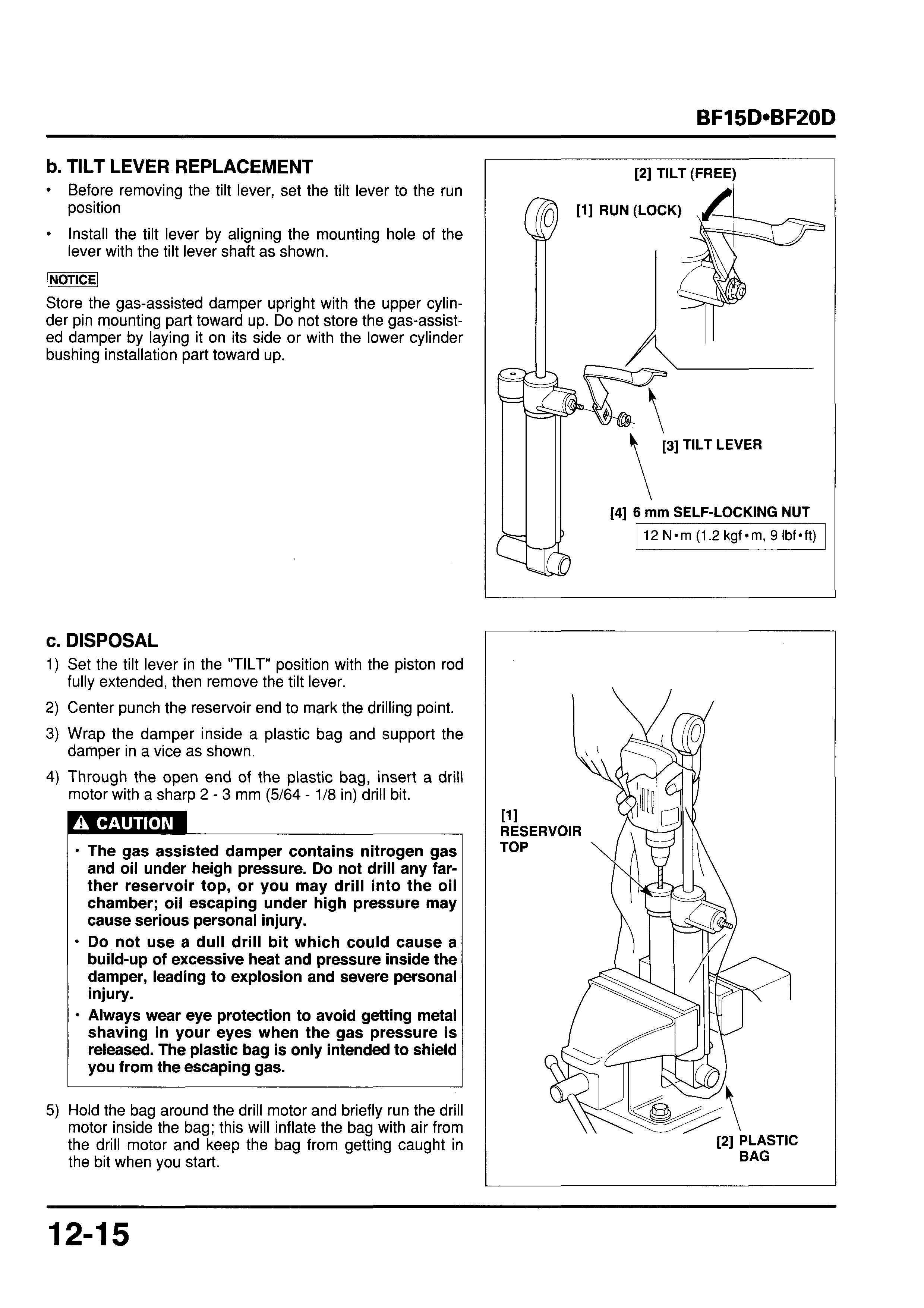
b. TILT LEVER REPLACEMENT
Before removing the tilt lever, set the tilt lever to the run position
Install the tilt lever by aligning the mounting hole of the lever with the tilt lever shaft as shown.
(NOTICE1
Store the gas-assisted damper upright with the upper cylinder pin mounting part toward up. Do not store the gas-assisted damper by laying it on its side or with the lower cylinder bushing installation part toward up.
c. DISPOSAL
1) Set the tilt lever in the "TILT" position with the piston rod
2) Center punch the reservoir end to mark the drilling point.
3) Wrap the damper inside a plastic bag and support the
4) Through the open end of the plastic bag, insert a drill fully extended, then remove the tilt lever. damper in a vice as shown. motor with a sharp 2 - 3 mm (5/64 - 1/8 in) drill bit.
The gas assisted damper contains nitrogen gas and oil under heigh pressure. Do not drill any farther reservoir top, or you may drill into the oil chamber; oil escaping under high pressure may cause serious personal injury.
Do not use a dull drill bit which could cause a build-up of excessive heat and pressure inside the damper, leading to explosion and severe personal injury.
Always wear eye protection to avoid getting metal shaving in your eyes when the gas pressure is released. The plastic bag is only intended to shield you from the escaping gas.
5) Hold the bag around the drill motor and briefly run the drill motor inside the bag; this will inflate the bag with air from the drill motor and keep the bag from getting caught in the bit when you start.
d. INSTALLATION
1) Install new lower cylinder bushings if they are removed.
2) Apply marine grease to the lower cylinder bushings and lower cylinder collar, then install the lower cylinder collar to the gas assisted dumper lower mount.
3) Apply marine grease to the swivel case bushings.
4) Install the gas assisted damper to the swivel case. Set the piston rod in the fully extended position before installation.
5) Install the upper cylinder pin through the right side of the swivel case as shown and secure it with the 15 mm external circlip.
6) Set the gas assisted damper to the lower mounting hole and install the 8 x 203 mm hex. bolt and 8 mm washer.
7) Tighten the 8 mm self-locking nut to the specified torque.
TORQUE: 21 N-m (2.1 kgf-m, 15 Ibf-ft)
Power Tilt Assembly Removal
Remove the following:
- remove the motor wire from the motor (P. 13-9)
- engine (section 8).
- oil case (P. 12-1).
- friction adjusting lever (Tiller handle type only P. 12-3).
- mount frame (P. 12-5).
Open the wire band and wire band clip and free the motor wire from the right stern bracket, then pull the motor wire from the left stern bracket with the motor wire bushing.
Remove the 6 x 8 mm screw and ground wire from the power tilt assembly.
Remove the adjusting rod.
Remove the 8 mm self-locking nut and 8 mm plain washer.
Remove the distance collar and lower cylinder collar. Tilt up the swivel case, and remove the 15 mm external circlip and upper cylinder pin and remove the power tilt assembly.
After removing the power tilt assembly, store it upright with the upper cylinder pin mounting part toward up. Do not store by laying it on its side or with the lower cylinder bushing installation part toward up.
b. DISASSEMBLY /NOTICE/
Do not disassemble the gear pump assembly. If it is faulty, replace it as an assembly.
Do not use a shop towel, cloth, gloves, etc.
Do not reuse the drained automatic transmission fluid (ATF).
Do not hold at the outer tube when holding the power tilt assembly in a vise during operation.
Clean the removed parts in fresh automatic transmission fluid (ATF), and blow each port of the parts with compressed air. Set the parts neatly in a suitable container with care not to contaminate them with dust and dirt.
Do not reuse the O-rings.
Remove each valve and sleeve with care not to damage the sliding surface of the parts.
Power Tilt Motor
1) Connect the power tilt motor 2P connector and operate the power tilt motor assembly until the piston rod extends fully.
2) Loosen the manual valve fully.
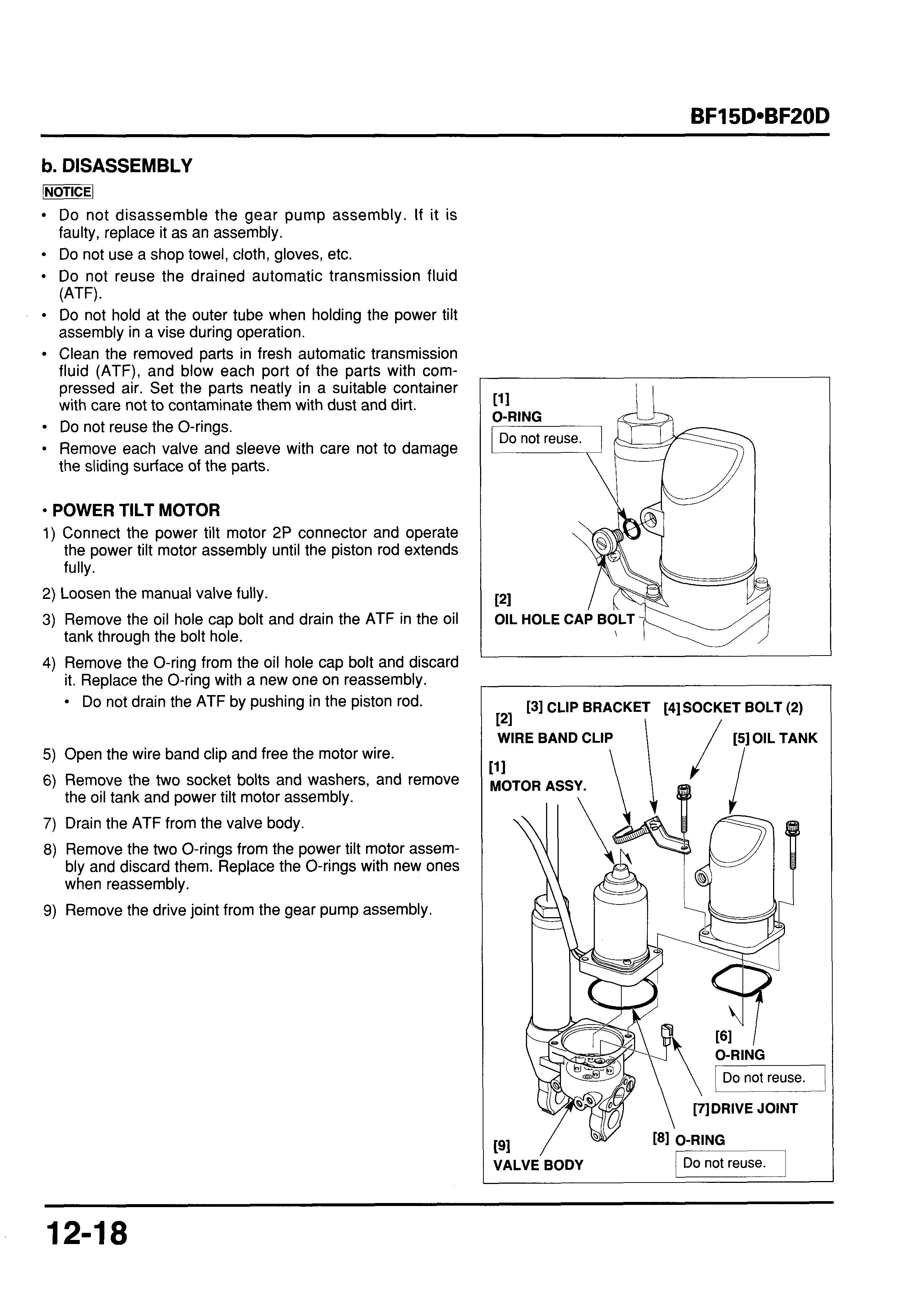
3) Remove the oil hole cap bolt and drain the ATF in the oil tank through the bolt hole.
4) Remove the O-ring from the oil hole cap bolt and discard it. Replace the O-ring with a new one on reassembly. Do not drain the ATF by pushing in the piston rod.
5) Open the wire band clip and free the motor wire.
6) Remove the two socket bolts and washers, and remove the oil tank and power tilt motor assembly.
7) Drain the ATF from the valve body.
8) Remove the two O-rings from the power tilt motor assembly and discard them. Replace the O-rings with new ones when reassembly.
9) Remove the drive joint from the gear pump assembly.
10) Remove the 5 mm screws, yoke and O-ring.
11)Pull off the brush spring end from the bracket.
Remove the armature.
CYLINDER, PISTON ROD
1) Hold the valve body in a vise with shop towel or soft jaws as shown.
Take care not to tighten the vise too tight as it damages the valve body
If it is need to disassemble the valve body, loosen the spool vale (P. 12-23).
2) Loosen the lock nut, then remove the upper joint metal and lock nut.
3) Loosen the outer tube, then remove the valve body from the vise.
4) Loosen the outer tube slowly. Drain the residual ATF from the outer tube and valve body and remove the outer tube from the valve body.
5) Remove the cylinder/piston assembly from the outer tube.
6) Remove the piston rod and free piston from the cylinder.
7) Remove the O-ring from the piston rod and discard it. Replace the O-ring with a new one when reassembly.
8) Remove the backup ring and O-ring from the free piston and discard them. Replace the backup ring and O-ring as a set when reassembly.
9) Remove the dust seal and O-ring from the outer tube and discard them. Replace the O-ring and dust seal with new one when reassembly.
Valve Body
1) Remove the two O-rings from the valve body and discard them. Replace the O-rings with the new ones when reassembly.
2) Remove the socket bolts and gear pump assembly.
Do not disassemble the gear pump assembly. If it is faulty, replace it as an assembly.
3) Remove the two O-rings, valve spring, spring guide, steel ball and the down relief valve seat from the valve body. Remove the O-ring from the down relief valve seat. Discard the O-rings, replace the O-rings with new ones when reassembly.
4) Remove the internal circlip, and remove the manual valve
5) Remove the O-ring and D-ring, and discard them. and seal washer. Replace with new ones when reassembly.
6) Remove the spool valve cap using a commercially available driver bit 2.8 mm.
7) Apply small squirt of air pressure to the oil hole in the spool valve cap to remove the valve B. Remove the valve B from the spool valve cap.
8) Remove the O-rings from the spool valve cap and valve B and discard them. Replace the O-rings with the new ones on reassembly.
121 DRIVER BIT, 2.8 mm (Commercially available)
9) Remove the spool valve from the valve body
Check the backup ring on the spool valve for damage and scratches. Replace the backup ring if it is damaged or scratched.
10)Process a piece of piano wire of 1.5 mm in diameter as shown.
11)Set the processed wire in the holes in both sides of the sleeve as shown, and secure the wire by inserting the 10 mrn bolt into the sleeve. Remove the sleeve from the valve body by pulling the wire with care not to damage the valve body.
Remove the O-ring from the sleeve and discard it. Replace the O-ring with a new one on reassembly.
[l] About 50 mm (1.0 in)
3 - 4 mm (0.12- 0.15 in) [2] \ I
12)Set the valve body as shown. Apply small squirt of air pressure to the manual valve installation hole to remove the valve B. Remove the valve B from the valve body
13)Remove the O-ring from the valve cornp. B. Replace the O-ring with a new one on reassembly.
c. INSPECTION
Down Relief Valve Seat
Check the down relief valve seat, spring guide and spring for wear or damage. Replace the down relief valve seat, spring guide or spring if damaged or worn.
CYLINDER, PISTON, FREE PISTON
Check the piston rod for damage and bent. Replace the piston rod with a new one if necessary.
Check the inner and outer surfaces of the cylinder for damage and scratch. Replace the cylinder with a new one if it is damaged or scratched.
Manual Valve Sealing Cup
Check the manual valve and seal washer for wear or damage and deterioration. Replace if it is damaged or deteriorated.
Spool Valves
Check the sliding surface of the valve 6, spool valve, sleeve for damage, scratch and wear, replace if necessary.
Power Tilt Motor
Brush
Measure the brush length.
If the brush length is less than the service limit, replace the brush holder assembly.
Standard I Service limit I
10 mm (0.4 in) I
6 mm (0.2 in) I
Armature
1) Check the armature for wear or damage. Replace if necessary.
2) Visually inspect the commutator surface for dust, rust or other damage. If necessary, wipe it with a clean lint-free cloth or dress with a fine emery cloth.
3) Measure the mica depth. If the grooves are clogged, clean the grooves and measure the depth again. If the measurement is less than the service limit, replace the armature.
Service limit
0.8 mm (0.03 in)
4) Check the bearing for play. Replace the armature if it has excessive play or abnormal noise.
5) Check for continuity between each segment. If an open circuit exists between any two segment, replace the armature.
6) Check for continuity between the commutator and armature coil core. If continuity exists, replace the armature.
7) Check for continuity between the commutator and armature shaft. If there is continuity, replace the armature.
d. REASSEMBLY VALVE BODY
WTXl
Do not reuse the O-ring.
Do not use a shop towel, cloth, gloves, etc when reassembly.
Assemble the parts with care not to let the foreign particles and dirt enter the valve body and gear pump assembly.
3: Apply ATF.
1) Clean the parts in the fresh ATF, and blow each port of the parts with compressed air. Check that the parts are free from contamination with dust and dirt before reassembly.
2) Apply the ATF to a new O-ring, and install it on the valve B.
3) Apply the ATF to the valve B and install the valve B in the valve body noting the installation direction.
4) Apply the ATF to a new O-ring, and install it on the sleeve.
5) Set the new backup ring on the spool valve and apply the ATF to the outer surface of the spool valve.
6) Install the spool valve in the sleeve noting the installation direction.
7) Apply the ATF to the sleeve, and install the sleeve in the valve body noting the installation direction.
8) Apply the ATF to a new O-ring, and install it on the valve
9) Apply the ATF to the valve B and install it in the spool
10)Apply the ATF to the new O-rings, and install the O-rings
B. valve cap noting the installation direction. on the spool valve cap.
11)Tighten the spool valve cap to the specified torque using the commercially available driver bit 2.8 mm.
TORQUE: 22 N m (2.2 kgf m, 16 Ibf ft)
12)Apply the ATF to the sealing washer, and set it in the valve body at right angles. Be careful not to set it at an inclined angle, which can lead to the collapsed sealing washer.
13)Apply the ATF to new O-ring and D-ring, and install them on the manual valve.
14)Tighten the manual valve to the specified torque, and set the internal circlip in the groove in the valve body secure-
TORQUE: 1.7 N m (0.17 kgf m, 1.2 Ibf ft) ly.
15)Apply the ATF to a new O-ring, and install it on the down
16)Apply the ATF to the down relief valve seat and install it
17)lnstall the steel ball, spring guide and the valve spring in
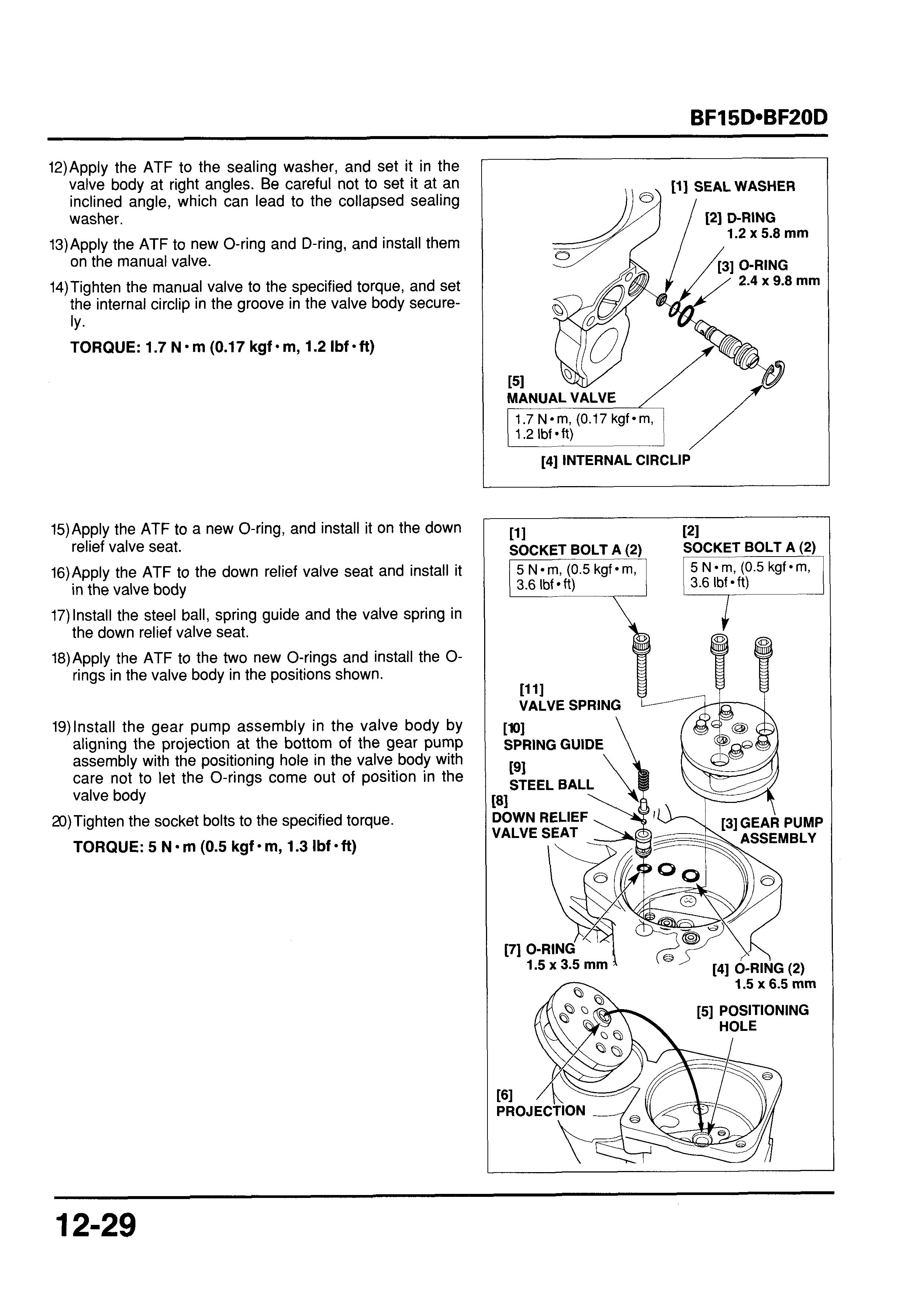
18)Apply the ATF to the two new O-rings and install the 0- relief valve seat. in the valve body the down relief valve seat. rings in the valve body in the positions shown.
19)lnstall the gear pump assembly in the valve body by aligning the projection at the bottom of the gear pump assembly with the positioning hole in the valve body with care not to let the O-rings come out of position in the valve body
20)Tighten the socket bolts to the specified torque.
TORQUE: 5 N m (0.5 kgf m, 1.3 Ibf eft)
CYLINDER, PISTON pmicq
Do not reuse the O-ring. Do not use a shop towel, cloth, gloves, etc when reassembly.
Assemble the parts with care not to let the foreign particles and dirt enter the valve body and gear pump assembly.
1) Clean the parts in the fresh ATF. Check that the parts are free from contamination with dust and dirt before reassembly.
3 : Apply ATF.
Apply the ATF to two new O-rings, and install the O-rings in the valve body
Install the smaller O-ring in the lower groove and the larger O-ring in the upper groove of the valve body
[l] O-RING 2.0 x 43.5 mm
1 Install in the upper groove.
[2] O-RING 2.0 x 34.5 mm
Apply the ATF to a new O-ring and backup ring, and install them on the free piston.
4) Apply the ATF to a new O-ring and install it on the piston rod.
5) Apply the ATF to the inner wall of the cylinder.
6) Install the free piston in the cylinder and pour the fresh ATF to the free piston.
7) Install the piston rod in the cylinder from the chamfered ends at the inside of the cylinder and push in the piston rod until the piston rod end aligns with the cylinder end as shown.
Take care not to damage the free piston O-ring and backup ring and the piston rod O-ring.
8) Apply the ATF to a new O-ring, and install it in the lower groove in the outer tube.
9) Apply the ATF to the new oil seal. Holding the oil seal with the fingers so that it shapes "U" and install it in the upper groove in the outer tube.
10)Attach a thin sealing tape around the threads at the end
11) Install the cylinder/piston assembly in the outer tube. of the piston rod.
When it is hard to install the piston rod end in the outer tube, apply the ATF to the piston rod end, then insert the piston rod into the outer tube by turning the outer tube.
Take care not to push the piston rod into the cylinder with force.
When the piston rod is pushed into the cylinder with force, push in the free piston in the cylinder as full as it goes with the threaded part of the piston rod facing down and by holding the outer tube and cylinder securely.
12)After installation, remove the sealing tape from the threads at the end of the piston rod.
Attach a thin sealing tape around the threads.
13)Turn the piston rod of the outer tube/piston rod assembly upside down and check whether the piston rood is extended fully.
14)Pour the fresh ATF into the cylinder and outer tube up to the top edge of the cylinder and outer tube.
15)lnstall the valve body on the outer tube that had been filled with the ATF in the previous step 14, and tighten the valve body
Install the valve body with care not to spill the ATF in the outer tube/piston rod assembly.
16) Hold the valve body in a vise as shown taking care not to tighten the vise too tight as it damages the valve body
17)Tighten the outer tube to the specified torque.
TORQUE: 152 N*m (15.5 kgf-m, 112 Ibf-ft)
POWER TILT MOTOR /NOTICE]
Do not reuse the O-ring. Do not use a shop towel, cloth, gloves, etc when reassembly.
ARMATURE
Remove the burrs at the armature shaft with a fine emery paper before assembly.
Take care not to damage the oil seal during assembly.
5 mm SCREW (2)
Make sure there is no metallic part (e.g. washer, etc.) the magnets before installation.
After installing the yoke, lightly tap on the outer surface of the yoke with a plastic hammer (for snug fitting of the armature bearing).
1) Set the brushes on the each holder.
2) Apply grease to the bearing and oil seal lip and install the armature.
Remove the burrs at the armature shaft with a fine emery paper before assembly.
Take care not to damage the oil seal during assembly.
3) Set the brush springs over the mounting pins of the brush
4) Set the lower straight part of the brush spring in the
5) Set the upper straight part of the brush spring on the holder. groove of the brush holder. hook of the brush holder.
6) Set a new O-ring on the brush holder.
7) Make sure there is no metallic part (e.g. washer, etc.) the magnets before installation.
8) Holed the armature shaft and install the yoke by aligning its projection with the concave in the brush holder.
9) Tighten the two screws securely. After tightening, be sure there is no lifting between the yoke and brush holder.
10)After assembly, lightly tap on the outer surface of the yoke with a plastic hammer (for snug fitting of the armature bearing).
11)Loosen the manual valve by turning it 3 turns or more.
12)lnstall the drive joint in the position of the gear pump assembly as shown.
13)Fill the gear pump chamber with the fresh ATF up to the upper edge of the chamber. If the ATF in the valve body contains air bubbles, remove the air bubbles using an oil bottle or equivalent tool.
Do not pour the ATF into the valve body gear pump chamber quickly. Pour the fluid slowly.
Trapped air in the system causes faulty operation. Remove the air bubbles in the fluid securely.
14)Apply the ATF to a new O-ring, and install it on the power tilt motor assembly.
15) Install the power tilt motor assembly on the valve body so that the power tilt motor wire is at the outer tube side and align the motor shaft with the groove of the drive joint as shown.
16)Apply the ATF to a new O-ring, and install it on the power tilt motor assembly.
17)lnstall the oil tank on the power tilt motor assembly so that the oil hole cap bolt mounting hole is at the motor wire side.
18)Set the wire band clip on the clip bracket, and secure the motor wire.
19)Tighten the two socket bolts to the specified torque.
TORQUE: 4.4 N m (0.45 kgf m, 3.3 Ibf ft)
f. ATF FILLING
1) Using a syringe or equivalent tool, add approximately 30 cm3 (1.01 US oz, 1.06 Imp oz) of the ATF slowly through the oil filler port of the oil tank.
2) After adding the fluid, tighten the manual valve securely. Wipe up the spilled ATF thoroughly. Be sure that the oil hole cap bolt is not tightened.
3) Connect a fully charged battery, power tilt relay, power tilt switch and motor so that the power tilt assembly can operate.
4) To bleed air in the ATF, lean the power tilt assembly to the left, viewed from the oil filler port side, several times slowly at an angle of 10" to 30" as shown.
5) Push the "DN" side of the power tilt switch and compress the piston rod fully.
6) Using a syringe or equivalent tool, add the ATF slowly until the fluid flows out of the oil filler port of the oil tank.
[2] SOCKET BOLT (2) -45 kgf m, 3.31bf.ft))
[3] OILTANK
7) Lean the power tilt assembly to the side as shown with the piston rod fully compressed. Push the "UP" side of the power tilt switch and extend the piston rod approximately 50 mm (2 in) from the end of the piston rod.
8) With the power tilt assembly inclined to the side, add the ATF to the oil tank slowly until the fluid flows out of the oil filler port by using a syringe or equivalent tool.
[l] Extend approx. 50 mm from the fully compressed position.
9) Push the "UP" side of the power tilt switch with the power tilt assembly inclined to the side, and extend the piston rod by additional 50 mm from the end of the piston rod.
10)With the power tilt assembly inclined to the side, add the ATF to the oil tank slowly until the fluid flows out of the oil filler port by using a syringe or equivalent tool.
[l] Extend by additional 50 mm.
121 Add the ATF up to the edge of the oil filler port.
11)With the power tilt assembly inclined to the side, push the "UP" side of the power tilt switch and extend the piston rod as full as it goes.
12)With the power tilt assembly inclined to the side, add the ATF to the oil tank slowly until the fluid flows out of the oil filler port by using a syringe or equivalent tool.
Eitend fully.
Add the ATF up to the edge of the oil filler port.
13)Set the power tilt assembly upright. Using a syringe or equivalent tool, catch the ATF flowing out of the oil filler port of the oil tank until the fluid level is at the edge of the filler port.
14)Check whether the ATF level is at the edge of the filler port.
[l] Add the ATF up to the 1 1 edge of the oil filler port.
15)lnstall the new O-ring on the oil hole cap bolt and tighten the oil hole cap bolt to the specified torque.
TORQUE: 1.1 N-m (0.11 kgf-m, 0.83 Ibf-ft)
16)Push the "UP" side and "DN" side of the power tilt switch, and check whether the piston rod moves smoothly. and switch.
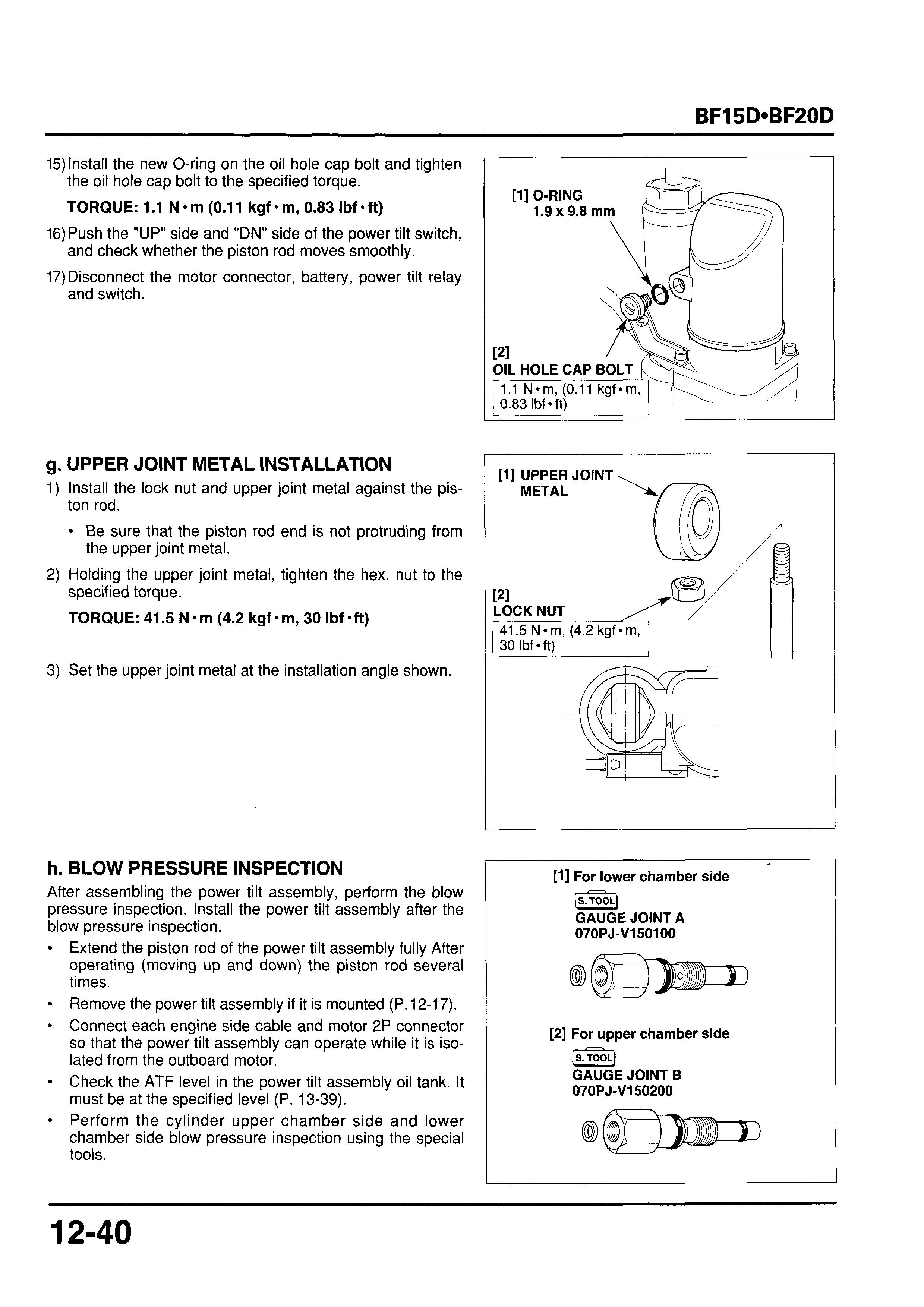
17)Disconnect the motor connector, battery, power tilt relay
g. UPPER JOINT METAL INSTALLATION
1) Install the lock nut and upper joint metal against the piston rod.
Be sure that the piston rod end is not protruding from the upper joint metal.
2) Holding the upper joint metal, tighten the hex. nut to the specified torque.
TORQUE: 41.5 N*m (4.2 kgf-m, 30 Ibf-ft)
3) Set the upper joint metal at the installation angle shown.
h. BLOW PRESSURE INSPECTION
After assembling the power tilt assembly, perform the blow pressure inspection. Install the power tilt assembly after the blow pressure inspection.
Extend the piston rod of the power tilt assembly fully After operating (moving up and down) the piston rod several times.
Remove the power tilt assembly if it is mounted (P. 12-17).
Connect each engine side cable and motor 2P connector so that the power tilt assembly can operate while it is isolated from the outboard motor.
Check the ATF level in the power tilt assembly oil tank. It must be at the specified level (P. 13-39).
0 Perform the cylinder upper chamber side and lower chamber side blow pressure inspection using the special tools.
A
Lower Chamber Side Blow Pressure
1) Remove the internal circlip, manual valve and sealing washer from the valve body Install the special tool (gauge joint body B) and the sealing washer, and tighten the special tool to the specified torque.
TORQUE: 1.7 N-m (0.17 kgf-m, 1.2 Ibf-ft) pi\
Be sure to remove the manual valve with the piston rod fully extended, or the ATF spurts out. A small amount of the ATF flows out after removing the valve. Install the special tool quickly. Install the sealing washer securely not to let it collapse in the valve body.
2) Attach a commercially available pressure gauge to the special tool that is set in the valve body
Use the pressure gauge which measures 50 Mpa (500 kgf/cm*, 7,000 psi) or above
Be sure that the ATF level in the oil tank is at the specified level (P. 13-39).
BLOW PRESSURE
(Lower chamber side)
4.26 - 5.00MPa (43.5 -51.O kgf/cm2, 619 - 725 psi)
If the blow pressure is out of the specified range, check each part of the power tilt assembly for oil leakage.
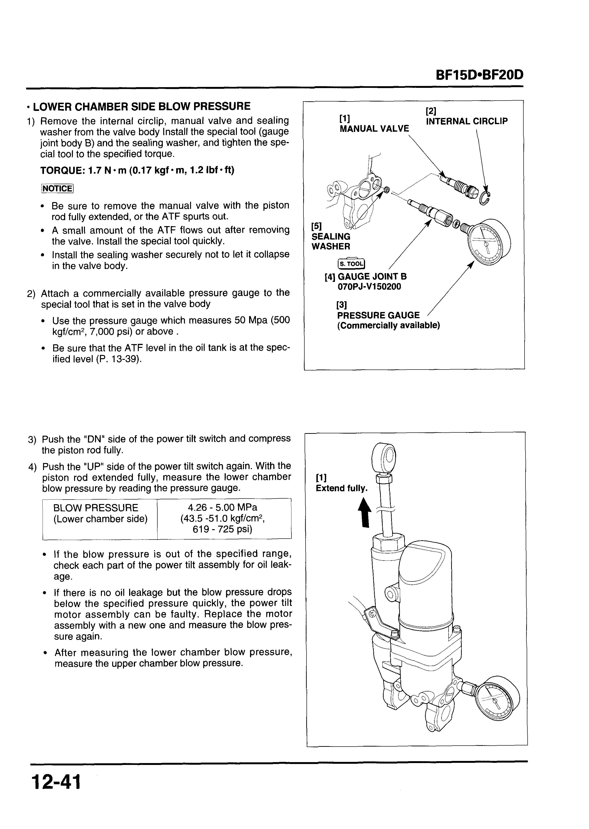
If there is no oil leakage but the blow pressure drops below the specified pressure quickly, the power tilt motor assembly can be faulty. Replace the motor assembly with a new one and measure the blow pressure again.
After measuring the lower chamber blow pressure, measure the upper chamber blow pressure.
Upper Chamber Blow Pressure
1) Remove the gauge joint body B that is for measurement of the lower chamber blow pressure from the valve body
Install the gauge joint body A that is for measurement of the upper chamber blow pressure in the valve body Tighten the special tool to the specified torque.
TORQUE: 1.7 N m (0.17 kgf m, 1.2 Ibf oft)
Be sure to remove the special tool with the piston rod fully extended, or the automatic transmission fluid spurts out.
A small amount of the ATF flows out after removing the gauge joint body B. Install the gauge joint body quickly.
Install the sealing washer securely not to let it collapse in the valve body
2) Attach a commercially available pressure gauge to the special tool that is set in the valve body.
Use the pressure gauge which measures 50 Mpa (500 kgf/cm2,7,000 psi) or above.
Be sure that the ATF level in the oil tank is at the specified level (P. 13-39).
[S.TOOLJ
BLOW PRESSURE (Upper chamber side)
If the blow pressure is out of the specified range, check each part of the power tilt assembly for oil leakage.
If there is no oil leakage but the blow pressure drops below the specified pressure quickly, the power tilt motor assembly can be faulty. Replace the motor assembly with a new one and measure the blow pressure again.
Sealing Washer
4) Push the "UP" side of the power tilt switch and extend the piston rod fully.
5) Remove the special tool and pressure gauge from the valve body Install the sealing washer, manual valve and the internal circlip in the valve body
Be sure to remove the special tool with the piston rod fully extended, or the ATF spurts out. A small amount of the ATF flows out after removing the tool. Install the manual valve quickly. Install the sealing washer securely not to let it collapse in the valve body.
6) Tighten the manual valve to the specified torque.
TORQUE: 1.7 N*m (0.17 kgf-m, 1.2 Ibf-ft)
7) With the piston rod fully extended, check whether the ATF level is at the edge of the filler port of the oil tank (P. 13-55). If the oil level is low, add the fluid (ATF) up to the edge of the filler port.
8) Install the power tilt assembly (P. 13-39).
141 PRESSURE GAUGE (Commercially available)
i. INSTALLATION
Apply marine grease to upper cylinder bushing.
Set the power tilt assembly to the swivel case as shown and install the upper cylinder pin and secure the 15 mm external circlip.
Apply grease to the lower cylinder bushings and lower cylinder collar, and install them on the power tilt assembly.
Install the distance collar on the lower cylinder collar and set the lower mount of the power tilt assembly between the stern bracket.
Install the 8 x 203 mm hex. bolt, 8 mm washer and 8 mm self-locking nut.
Pass the motor wire through the left stern bracket and set the motor wire bushing by aligning the boss of the bushing with groove on the left stern bracket as shown.
111
--
[15] LEFT STERN BRACKET / 41 MOTOR WIRE BUSHING
15 mm EXTERNAL
[4] 8x203mm HEX. BOLT
ADJUSTING ROD a. R EMOVAUINSTALLATION
After assembly, check the power tilt operation. Loosen the manual valve and check the manual tilting operation. Clicking sound can be heard when the outboard motor is tilted up fast with the manual valve set in the TILT position. Note that this is normal. When the tilt up speed is fast, the sound is mechanically produced as the free piston failed to synchronize with the piston movement.
1.
1.
1) Remove the engine cover.
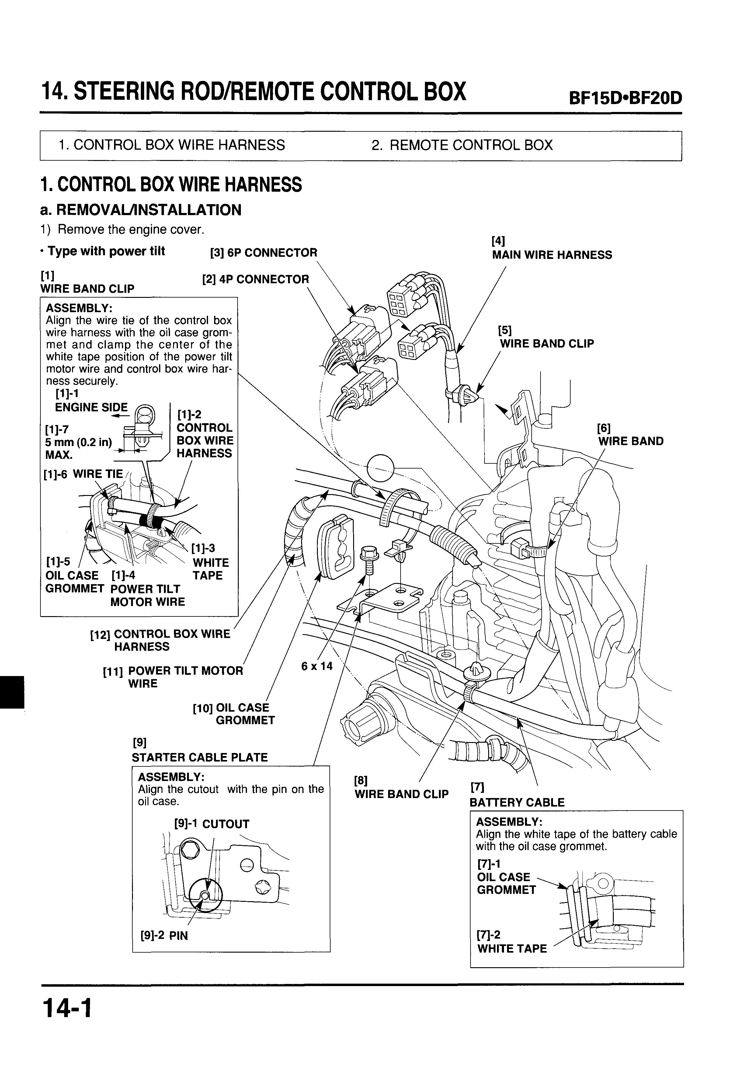
Type with power tilt [3] 6P CONNECTOR
2.
ASSEMBLY:
171
ASSEMBLY:
2. REMOTE CONTROL BOX
a. DlSASSEMBLYlREASSEMBLY ELECTRICAL EQUIPMENT
Type with power tilt [11
WARNING BUZZER the base shop manual I I
[15] 5x8mm SELF-TAPPING --..
PI
[2] WIRE BAND EMERGENCY STOP
FEkmI the base shop manual
IGNITION SWITCH
1131
POWER TILT SWITCH
REASSEMBLY: P. 14-3 INSPFCTION. P 1A-3
[14] CORD CLAMP - -- - -
[ll] INDICATOR
[lo] WARNING BUZZE IGNITION SWITCH
b. INSPECTION
POWER TILT SWITCH
Check for continuity between the terminals according to the table below.
There should be continuity between 0-0. 1x1
Light green 1
White/black 1 Light blue I
I UP 1-1 I
Neutral H


