V. OPERATING INFORMATION HYDRAULIC SYSTEM CONTINUED
Power Steering The full-time power steering system consists
3
of a hydraulic steering motor (mounted on the end of the steering wheel shaft) which is 2
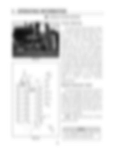
connected to a pair of double-action steering cylinders (fig. 5.15, item 1) mounted on a steering pivot (fig. 5.15, item 2) which oscillates
1
a pair of tie rods (item 5.15, item 3) going to each steering leg. This system is powered by one of the hydraulic dual gear pumps driven by
FIG 5.15
the sprayer’s engine. Since these gear pumps are sensitive to engine RPM (the higher the RPM the higher the oil flow), it is best to always
1
operate the detasseler at full recommended RPM
to
e nsure
ma xim um
st ee ring
responsiveness.
Electro-Hydraulic Valve The electro-hydraulic valve which control the height of the detasseler head lift cylinders is equipped with adjustable raise and lower orifices controlled by independent coils (fig 5.16, item 1). Upon initial setup adjust the orifice screws (fig. 5.16, item 2) as follows, then see page 51 for more precise adjustment: 2
RAISE – Adjust bolt all the way in and then back it out 2½ turns.
NOTE: Over adjustment of raise orifice can cause excessive working pressure. FIG 5.16


