CHAPTER 10 PREPARING FOR FIELD OPERATION the Harvester Tongue with the tractor drawbar and reduce the amount of side to side movement. The tractor drawbar height should be adjusted to position the PTO as parallel as possible to the drawbar. Keeping the drawbar in-line and minimizing side to side movement is essential in eliminating drive-line vibration, especially when maneuvering corners.
The Harvester, having a 1000 RPM 1-3/8″ PTO shaft or 1-3/4″ PTO shaft configuration, utilizes an equal angle drive length of 21.5″ (546 mm). This horizontal dimension is measured from the locking ring groove on the tractor PTO to the center of the drawbar pin hole. To operate the 1-3/8″ drive, your tractor must have an extendable drawbar. If your tractor does not have this feature, a 4″ (102 mm) Quick Attach Drawbar Extension is available.
2
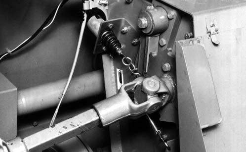
On tractors that are unable to adjust the drawbar to the proper dimension, a 4 inch (102 mm) Quick Attach Drawbar Extension is available. Refer to Figure 73 for proper positioning.
8
3
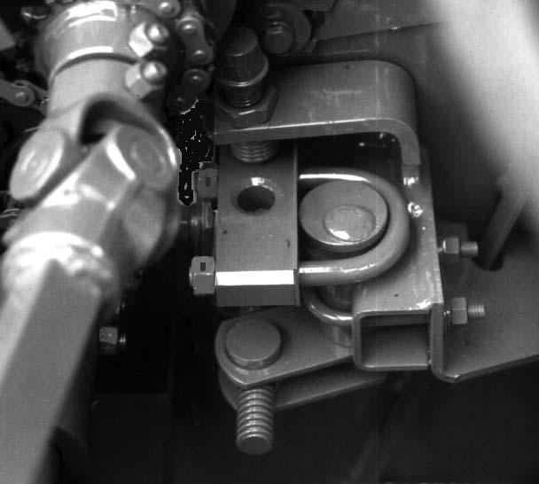
The front to rear position of the tractor drawbar hitch hole centerline MUST be correct to insure the proper Universal Joint relationship. The tractor drawbar hole should be 21″ (533 mm) from the locking ring of the tractor PTO Shaft, or 17″ (432 mm) from the locking ring of the tractor PTO Shaft when using the 4 inch (102 mm) Quick Attach Drawbar Extension.
4
5 6
1
7
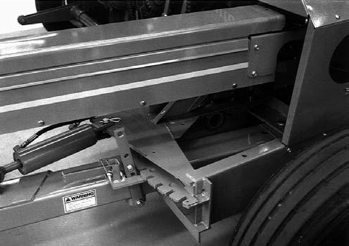
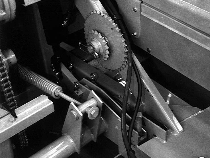
1 – Tractor Drawbar* 2 – 1000 RPM Tractor 1-3/8″ or 1-3/4″ PTO Shaft* 3 – 21.5″ (546 mm), This is measured from the Retaining Groove in the Tractor PTO Shaft to the center of the Tractor Drawbar Hitch Pin hole. 4 – 21.5″ (546 mm), This is measured from the Retaining Groove in the Harvester Main Drive Shaft to center of the Tractor Drawbar Hitch Pin hole. 5 – 7.9 to 13.8″(150 to 300 mm)* 6 – 13 to 22″ (330 to 560 mm)* (Top of Drawbar to Ground) 7 – Locking Hitch Pin [1 inch (25 mm) diameter] 8 – Tractor Drawbar Hitch Pin Hole Alignment Decal on PTO
2
3
4
1 5
6
9
7
1 – Tractor Drawbar* 2 – 1000 RPM Tractor 1-3/8″ or 1-3/4″ PTO Shaft* 3 – 21.5″ (546 mm), This is measured from the Retaining Groove in the Tractor PTO Shaft to the center of the Tractor Drawbar Hitch Pin hole. 4 – 21.5″ (546 mm), This is measured from the Retaining Groove in the Harvester Main Drive Shaft to center of the Tractor Drawbar Hitch Pin hole. 5 – 7.9 to 13.8″(150 to 300 mm)* 6 – 13 to 22″ (330 to 560 mm)* (Top of Drawbar to Ground) 7 – Locking Hitch Pin [1 inch (25 mm) diameter] 8 – Tractor Drawbar Hitch Pin Hole Alignment Decal on PTO 9 – 4″ (102 mm) Quick Attach Hitch Extension
* Tractor MUST comply with ASAE Standard S203
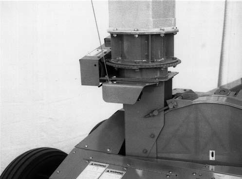
Fig. 72: 1-3/8″ or 1-3/4″ PTO 1000 RPM
TRACTOR HITCH ALIGNMENT (Figs. 72 & 73) Position the tractor drawbar hitch hole centerline directly in-line with the tractor PTO Drive Shaft, and secure so as to eliminate any side to side movement of the tractor drawbar. If the tractor drawbar can NOT be positioned in-line, position it toward the left, as close as possible to the centerline of the PTO shaft. It is important to use a 1″ (25 mm) diameter Hitchpin (customer furnished) with the Harvester to help center
908018/AP0499
8
* Tractor MUST comply with ASAE Standard S203
Fig. 73: 1-3/8″ or 1-3/4″ PTO 1000 RPM with 4″ (102 mm) Quick Attach Hitch Extension
80
Printed in U.S.A.