18 minute read
CHAPTER 9 SERVICE WARNING

BEFORE servicing this unit, exercise the MANDATORY SAFETY SHUTDOWN PROCEDURE (page 8).
NOTE: The following information is referred to in both the Troubleshooting Guide and the Maintenance Schedule chapters of this manual. It should be understood that all services detailed in this chapter are Owner-Operator responsibilities. Where indicated, certain service routines should only be carried out under the direction of an authorized GEHL equipment dealer. Furthermore, all Hydraulic Motors, Hoses and Fittings should be routinely checked after every 100 hours of operation for leaks and secure attachment.
Bevel Gearbox
IMPORTANT: Internal Bevel Gearbox component repairs and replacements should only be performed by (or under the direction of) an authorized Gehl dealer. The Bevel Gearbox is a mechanism that requires special tools and training to repair; only your Gehl dealer has the facilities and trained personnel to provide this service.
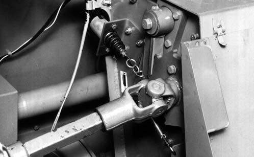
BLOWER Drive Belt (Fig. 49)
The Blower Drive Belt should be checked for cracks, tears and evidence of oil after every 50 hours of operation. To remove the Belt, lift the Idler Arm to relieve Belt tension. The use of a pipe or breaker bar as an aid is suggested. Move the Belt clear of the Idler and then release the Idler Arm tension. Guide the Belt off of the Drive and Driven Sheaves. To install a new Belt, reverse the removal process. Make sure that the new Belt is completely into the Grooves of the Sheaves before lowering the Idler.
1 – Retaining Washer
2 – Idler
3 – Driven Sheave
4 – Drive Belt
5 – Drive Sheave
6 – Idler Arm
Drive Sheave (Fig. 49)
IMPORTANT: The Bevel Gearbox MUST be removed from the Harvester Frame in order to remove the Drive Sheave. This procedure should be performed by (or under the direction of) an authorized Gehl dealer. Make sure to use thread locking compound on the retaining Bolt.
Blower Driven Sheave (Fig. 49)
Release Drive Belt tension and remove the Belt from the Blower Driven Sheave. Then, remove and retain the Bolt and Washer from the end of the Blower Shaft. The Driven Shaft can now be removed from the Blower Shaft. When reassembling the Sheave onto the Blower Shaft, reinstall the Retaining Washer, Lock Washer and Retaining Bolt using thread locking compound. Tighten the Bolt with 60 to 70 lb–ft (83–95 Nm) torque.
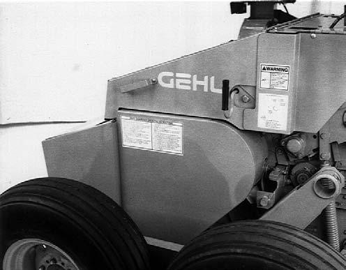
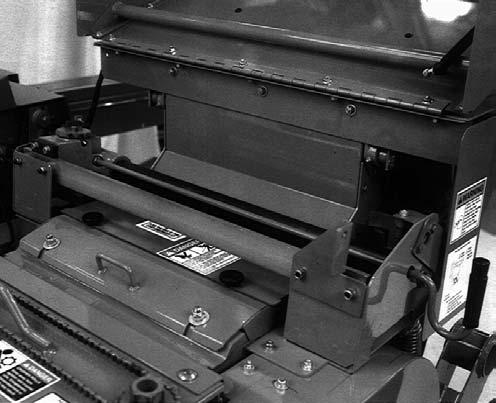
Rim Sheet Wear Liner (Figs. 50 & 51)
The Blower Rim Sheet Wear Liner should be inspected after every 100 hours of operation. The Rim Sheet assembly should always be kept tightly secured to prevent cut forage from wedging between the Rim Sheet grooves and the Blower Sidesheets.
IMPORTANT: If the Blower Fan requires removal for service or the Rim Sheet Wear Liner has to be removed and replaced, the following procedure should be performed. In addition, DO NOT transport the Harvester without securing the Rim Sheet in place; doing so could result in damage to the Blower Outlet or Sidesheets.
Rim Sheet Removal
1.Remove and retain the (10) fasteners which secure the Rear Left Shield assembly and remove the assembly. Remove the fastener retaining the triangular Shield between the Blower and Auger and remove the Shield.
2.Loosen and remove the two 1/2″ Take–up Bolts which tension the Rim Sheet.
3.Remove the three 5/16″ Plow Bolts from the bottom of the Outlet at the point where the Rim Sheet assembly is attached to the Outlet.
4.To loosen the Rim Sheet assembly, a 2 x 4″ wooden block MUST be used through the Blower Inlet hole and the access hole in the rear Sidesheet. While striking against the Rim Sheet assembly with the wooden block, rotate and slide the Rim Sheet down so that the end with the (3) holes can be freed from the between the Outlet and the Blower Side Sheets.
5.Move the top of the Rim Sheet assembly away from the Outlet.
6.After both ends of the Rim Sheet are loose, pull the top end to the rear of the Outlet while rotating it counterclockwise.
7.Remove the Wear Liner from the removeable Rim Shell.
NOTE: After the Rim Sheet assembly has been removed, clean the outside edges of the front and rear Blower Side Sheets.
Wear Liner Installation & Rim Sheet Assembly Replacement
8.Preassemble the three pieces of the Rim Sheet.
a.Properly position and attach the Removable Rim Shell to the Rim Sheet with the Spacer and (3 each) 5/16 x 3/4″ Flat Head Socket Head Cap Screws, Lock Washers and Nuts. Tightly secure the attaching hardware. If removable Rim Shell is NOT replaced, disregard this step.
b.Properly align and loosely attach the Wear Liner to the Rim Shell Section with (8 each) 5/16 x 3/4″ Plow Bolts, Plain Washers, Lock Washers and Nuts; hardware will be tightly secured after Rim Sheet is in position on Harvester (following step 11).
1 – Rim Sheet Assembly
2 – Wear Liner*
3 – 5/16 x 1 Plow Bolts, Lock Washers & Nuts (3 each)
4 – 5/16 x 3/4 Plow Bolts, Plain Washers, Lock Washers & Nuts (8 each)*
5 – 5/16 x 3/4 Flat Head Socket Cap Screws, Lock Washers & Nuts (3 each)*
6 – Spacer
7 – Removable Rim Shell c.Clean out all paint and foreign material from the Rim Sheet grooves. Then, apply a light coating of grease into the grooves around the entire edge of the Rim Sheet assembly.
* Included in Rim Liner Kit 094948.
9.Properly position and install the 3-piece Rim Sheet in somewhat the reverse manner as the original Rim Sheet assembly was removed.
NOTE: When the Rim Sheet is being installed, it may become hung up on the transition point at the base of the Blower Outlet. To facilitate moving the Rim Sheet past this transition, it may be necessary to slide a thin sheet of material past this point, which can serve as a guide for the end of the Rim Sheet.
10.Guide the end with the (3) holes between the Blower Side Sheets and the Outlet. Using a drift punch, align the holes in the Rim Sheet and Liner with the holes in the Outlet and tightly secure the three parts with (3 each) 5/16 x 1″ Plow Bolts, Lock Washers and Nuts.
11.With the Rim Sheet assembly correctly aligned and using a rubber mallet, block of wood or soft mallet, tap along the Side Sheet edges of the Rim Sheet, starting at the Blower Outlet end, to properly seat the Blower Side Sheets into the Rim Sheet grooves.
12.Reinstall the Takeup Bolts and, in an alternating manner, tighten two Nuts while striking against the Rim Sheet Beads to seat the Rim Sheet assembly. Secure the Takeup Nuts with 40 ft-lb (54 Nm) of torque and tighten the Jam Nuts.
13.After the 3-piece Rim Sheet is properly installed and secured tightly secure the Wear Liner hard ware in the manner defined by the drawing (Fig. 51).
14.Rotate the Blower Fan, by hand, to check for interference.
15.Readjust the Fan Paddles following the details in the Adjustment chapter of your manual.
IMPORTANT: After the first 10 hours of operation following Rim Sheet assembly or replacement, the Take-up Nuts torque should be checked and readjusted to 40 lb–ft (54 Nm), as necessary.
CHAINS & SPROCKETS
Sprocket wear is most often caused by an excessively worn Chain. A Chain that has worn 3% (1.03 times the original length) should be removed and replaced.
This Harvester is designed so that when the Chain Tightener reaches the limit of its adjustment, the Chain has reached a condition of maximum wear. To calculate the original Chain length, multiply the number of Links times 3/4″ for a #60 Chain, or times 5/8″ for a #50 Chain.
Cutting Mechanism
(Figs. 52 thru 56)
Shear Bar
The edge of the reversible Shear Bar will remain sharp provided the Knives are kept sharp and the Shear Bar is properly set up to the Knives. When the cutting edge NO longer stays sharp, the Shear Bar can be removed and changed (end-for-end) to place a new sharp edge toward the Knives. To remove and replace the Shear Bar, proceed as follows:
Removal
NOTE: Depending on the size of the Tires, Spindle height and position of the Axle Extension, it may be necessary to remove the Wheel or move the Axle Extension out on the right side of the Harvester to obtain clearance for removing the Shear Bar.
1.Do NOT remove, loosen or alter the position of the Shear Bar Hold-down Pin on the left side.
2.Loosen and remove the Lock Nuts, Slot Baffle and Shear Bar Cam U-Bolt on the left side; retain all attaching hardware. BE SURE to use new Lock Nuts when Shear Bar is replaced.
3.Remove the Right Side Shield that covers the Sheave and/or Cutting Cylinder Shaft. If more room is desired, remove the Processor Mill Drive Belts and/or the Right Guard.
4.Remove the front Shear Bar Right Adjustment Nut.
5.Pry the spring loaded Bolt Lock off the Adjustment Bolt and swing it away from the side of the harvester. Move the adjustment Bolt towards the rear of the harvester while holding the rear Shear Bar Nut. Continue until the Adjustment Bolt is clear of the Shear Bar.
6.Remove the right side Shear Bar Clamp Bolt and Washer.
NOTE: In order to remove the Shear Bar, it may be necessary to loosen both pairs of Stem Guide mounting bolts and move the Stem Guides up to free the Shear Bar. After the Guides are moved, retighten the bolts to keep the Guides away while replacing the Shear Bar.
7.From the right side, pull the Shear Bar out from under the left side Shear Bar Hold-down Pin and remove the Shear Bar.
1 – Stem Guide Mounting Bolts (Both Sides)
2 – Right Side Clamp Bolt
3 – Shear Bar Right Adjustment Nuts (2)
4 – Smooth Feed Roll Scraper
5 – Remote Left Shear Bar Adjustment
6 – Adjustment Bolt
8.Before attempting to replace the Shear Bar or install a new Shear Bar, BE SURE that it is thoroughly cleaned. In addition, clean off the Shear Bar Support behind the Smooth Feed Roll Scraper. Apply grease or a lubricant to the entire bottom side of the Shear Bar to facilitate sliding it back into its mounting position and to facilitate adjustment.
9.Install the Shear Bar so the triangular notches are facing up. Force the Left end of the Shear Bar under the Spring-loaded Shear Bar Hold-down Pin on the left side.
10.Do NOT attempt to loosen the left side Hold-down Pin Sleeve. Make sure however, that the Pin is free to slide in its Sleeve.
11.Install the Shear Bar so that its right end is flush with the end of the Shear Bar Support.
1 – Plastic Cover Over Sleeve
2 – Cotterpin
3 – Hold-down Pin Sleeve
4 – Left Cylinder Side Sheet
5 – 3/4″ Locking Nut
6 – Left Side Shear Bar Hold-down Pin
7 – Shear Bar Support
8 – Spring Washers

9 – 5/8″ (16 mm)
Fig. 55: Left Side Hold-down Assembly
NOTE: If the right side Lock Plate Bolt was loosened or removed, reassemble all parts per Figure 56.
12.Move the right side Adjustment Bolt until it enters the Shear Bar. Make sure one Shear Bar Nut is positioned between the Frame and Shear Bar.
13.Install and tighten the right side Clamp Bolt, Washer and Locking Nut.
14.Move the right side Adjustment Bolt forward until it clamps the Belleville Spring Washer flat. Loosen the Bolt EXACTLY 1/3 to 1/2 turn (2-3 flats) and install the Spring Loaded Boltlock.
15.Apply grease in the Shear Bar Cam groove and reinstall the left side Shear Bar Cam U-Bolt, the Slot Baffle and the Lock Nuts. Torque the Lock Nuts so that the U-Bolt pulls the Cam tightly against the Slot Baffle and Shear Bar.
16.Reinstall the Right Guard and the Processor Mill Drive Belts, if they were removed. Reinstall the Right Shield that covers the Sheave and/or Cutting Cylinder Shaft.
Refer to the Shear Bar topic in the Adjustments chapter to make the proper Shear Bar adjustments for operation. BE SURE to reset the Stem Guide positions if they had been changed. Set the Stem Guides down against the Shear Bar and make sure that they are clearing the Cutting Cylinder by 1/32 to 1/16″ (0.8 to 1.6 mm) to prevent damage to the Knives. Then, retighten the Stem Guide Bolts.
IMPORTANT: Be sure to tighten the Stem Guide Mounting Bolts, because loose bolts will allow the crop to push the Stem Guides into the Knives and severely damage the Cutting Cylinder.
Knife Replacement (Fig. 57)
After numerous sharpenings, Knives will be ground down to where the hard-facing has disappeared. In addition, Knives may become deeply gouged or broken and require replacement. To replace a Knife, proceed as follows:
Warning
Exercise the MANDATORY SAFETY SHUTDOWN PROCEDURE (page 8) before servicing this unit.
1.Move the Shear Bar forward to the end of its adjustment slots. The space between the Shear Bar and Scraper will first have to be cleaned of debris.

2.Loosen and remove the (3) 3/4″ Bolts which secure the Knife. The Knife Header Plate prevents the Nut from turning, so, the 3/4″ Bolts will have to be held up in order to position the Nut between the Plates and prevent the Nut from turning.
3.Position a new Knife in place and insert three 3/4″ Bolts through the Lock Washers, Knife and Nuts. Partially tighten the Bolts, but NOT so tight that the Knives cannot be adjusted.
tighten the 3/4″ Bolts with 220 to 240 lb–ft (300-325 Nm) of torque. Do not over–torque!
5.Rotate the Cylinder by hand to check for interference.
Remove and store the Knife Set–up Rod. Reinstall all removed components EXCEPT the Cylinder Cover Sharpener Access Insert. Sharpen the Knives and set the Shear Bar according to the instructions under those topics.
NOTE: BE SURE to control the balancing of the Cutting Cylinder Knives when mixing old and new Knives. An old Knife should ALWAYS be balanced on the opposite side of the Cylinder with another old Knife and a new Knife should ALWAYS be balanced on the opposite side with another new Knife.
KNIFE SHARPENING (Figs. 58–60)
General Information
The Knife Sharpener is designed to operate by having a sharpening stone come in contact with the Cylinder Knives while the Cylinder is rotating in a reversed direction. The tractor PTO will supply power to rotate the Cylinder in reverse through a reversing transmission located on the front of the Harvester Tongue.
Preparation
1.Make sure that Cutterhead and Conveyor are clear of material before sharpening Knives or setting Shear Bar.
2.Shut off the PTO and tractor engine and make sure all parts have stopped rotating before removing Shields and Covers.
3.Open the Sharpener Cover.
4.Remove the narrow Cylinder Access Cover.
5.Verify proper Stone position or adjust as necessary to be just clear of the Cylinder Knives.
6.To retract the Stone, loosen the hardware on the Ratchet Wheel’s flat Spring and rotate the Wheel clockwise.
1 – Knife Setup Rod
4.Place the 1/2″ Knife Setup Rod into position in the holes in the Sidesheets and follow the procedure outlined in the “Knife Adjustment” and “Shear Bar Adjustment” text in this chapter. BE SURE to
7.ALWAYS use the Sharpener Handle to move the Sharpener Carriage.
8.To advance the Stone, pull the Sharpener Carriage completely to the right end of travel. This will engage the Ratchet Wheel into the Advancing Pawl. Each Pawl engagement advances the Stone 0.0046 inch (0.118 mm).
9.Close all Shields and the Sharpener Cover.
11.Start the tractor engine and engage the PTO slowly. Run the PTO speed up to 900 RPM for sharpening. Leave attachment drive in neutral.
12.ALWAYS wear safety goggles (provided) when sharpening Knives.
13.To sharpen, pull Stone across Knives using the Sharpener Handle. Advance Stone as necessary by pulling the Sharpener Handle completely to the right end of travel.
IMPORTANT: Move the Carriage in a smooth motion across the entire length of the Knife to prevent burning and to insure a smooth, uniform grind.
14.After some amount of Stone cycling, disengage PTO, Shut off tractor, wait for the Cutterhead to stop, open Sharpener Cover and check Knives for sharpness.
15.After the Knives are sharp, reinstall the implement end of the PTO to the upper (forward rotation) Shaft. Reinstall the Cylinder Access Cover and all Shielding.
16.Set the Shear Bar using instructions under that topic in the Operator’s Manual.

Stone Replacement (Fig. 61)
The Knife Sharpening Stone should be replaced when it has been worn to 1/8″ (3 mm) remaining between the cutting surface of the Stone and the Stone Clamp. To replace the Stone, remove the two socket head cap screws that hold the Locking Plate in place and remove the worn Stone. Thoroughly clean the Stone Clamp, Locking Plate and screws. Lightly coat the beveled sides of the Locking Plate and Stone clamp with grease and assemble with the new Stone. Torque the socket head cap screws to 20 ft lb (27 Nm). Do NOT over–torque!
Tension is controled by adding or removing Shims to change the spring tension of the Belleville Washer.
Sharpener Carriage Rails (Fig. 61)
Both the front and rear Carriage Rails need to be clean to assure a smooth, minimum resistance Carriage movement. The Slide Block on the rear Rail is adjustable so a 0.010–0.020″ (0.25–0.5 mm) clearance between the rear Rail and the lower roller bearing Follower can be maintained.
Ratchet Pawl (Fig. 62)
The Pawl which engages the Ratchet Wheel of the Stone Advance mechanism may require periodic adjustment. This is accomplished by turning the 5/16″ Lock Nut to obtain a 0.10″ (2.5 mm) dimension as indicated between the Mounting Bracket and the tip of the Pawl.
1 – 1/8″ (3 mm) Wear Measured Here
2 – Sharpening Stone
3 – Locking Plate
4 – Stone Clamp
5 – Socket Head Cap Screw 5/16 x 3/4″
6 – Grease Lightly Here
7 – 0.010-0.020″ (0.25-0.5 mm) Measured Here
8 – Carriage Rail
9 – Slide Block
10 – Roller Bearing Follower
11 – Ratchet Wheel Tension Shims
Fig. 61
Ratchet Wheel Tension (Fig. 61)
The Ratchet Wheel is tensioned so that a force of 50 to 120 in lb (5.7 to 14 Nm) is required to turn the Wheel.
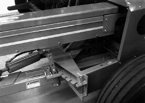
DEFLECTOR (Fig. 63)
A replaceable Liner is built into the Deflector which can be removed by taking-out (8) Plow Bolts. After the hardware is removed, the Liner can be guided through the Deflector and removed from the Cap end, without taking the Deflector off the Blower Outlet. To facilitate removal, it may be necessary to temporarily remove a Horizontal Deflector Extension, if present. New Liner installation is in reverse of old Liner removal. As necessary, remove any or all of the Cleanout Hole Covers for access to the Liner and Plow Bolts.
Remote Grease Lines
Several Steel Remote Grease Lines are provided on the Harvester to facilitate lubrication of otherwise difficult to reach relubeable Bearings. If a Steel Remote Grease Line is damaged or broken, it can be replaced by ordering a Tubing Kit (Gehl #065185).
Procedures for Steel Grease Line replacement are covered in Instructions packaged with the Kit.
Shifter Transmission
IMPORTANT: Shifter Transmission component repairs and replacements should only be performed by (or under the direction of) an authorized Gehl dealer. The Transmission is a mechanism that requires special tools and training to repair. Only your Gehl dealer has the facilities and trained personnel to provide this service.
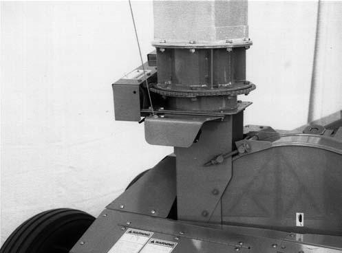
SPEED MONITOR (Fig. 64)
The Speed Monitor Module is NOT repairable. If it is
NOT operating properly, your dealer will have to determine if it MUST be replaced.
The Speed Monitor Module is mounted on a Bracket on the left side of the Auger Housing. When replacing the Speed Monitor, make sure that it is installed so that the Magnetic Pickup of the Module is centered directly over the Monitor Gear. Also, the air gap must be set [0.06 to 0.22″ (1.5 to 5.5mm)] to assure proper operation.

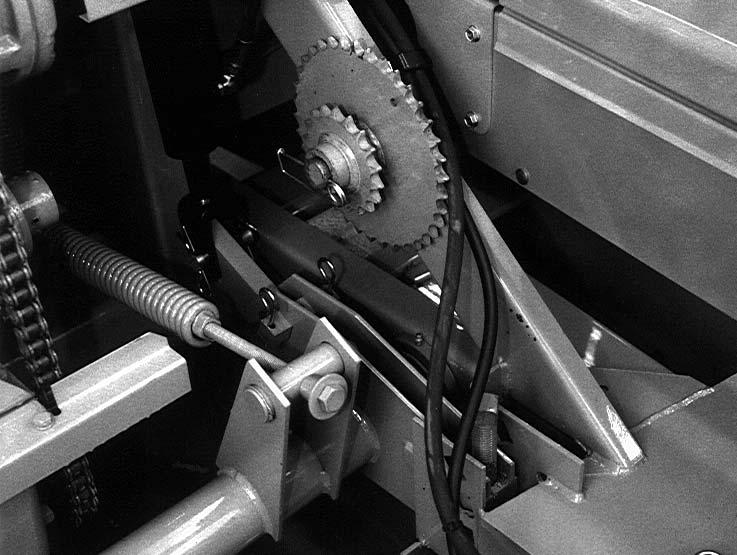
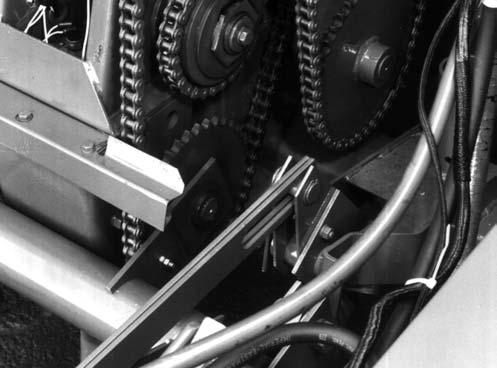
AUGER DRIVE CHAIN (Fig. 65)
The Auger is driven by a Chain. The Drive Sprocket for the Chain is located on the Cutting Cylinder Shaft. When the Drive Chain is removed, the Auger should be free to rotate. For access to the Drive Chain and Idlers, remove the Drive Guard.

TIRES & WHEELS
The GEHL Company does NOT sell replacement tires. In addition, tire mounting, repair and replacements should ONLY be attempted by a qualified tire manufacturer’s representative or by properly trained personnel following the tire manufacturer’s instruction. If you do not have such instructions, contact your tire dealer or the GEHL Company.
Warning
Inflating or servicing tires can be dangerous. Whenever possible, trained personnel should be called to service and/or mount tires. In addition, DO NOT place fingers on tire bead during inflation; serious injury or amputation could result! In any event, to avoid possible injury, follow the safety precautions below:
• BE SURE the rim is clean and free of rust. Lubricate both the tire beads and rim flanges with a soap solution. Do NOT use oil or grease. Do NOT weld, braze, or otherwise attempt to repair and use a damaged rim.
• Use a clip-on tire chuck with a remote hose and gauge, which allows you to stand clear of the tire while inflating it.
• NEVER inflate beyond 35 PSI (240 kPa) to seat the beads. If beads have not seated by the time the pressure reaches 35 PSI, deflate the assembly, reposition the tire on the rim, relubricate both parts and re-inflate it. Inflation pressure beyond 35 PSI with unseated beads may break the bead or rim with explosive force sufficient to cause fatal or serious injury.
• After seating the beads, adjust the inflation pressure to the recommended operating pressure listed.
Check the Forage Harvester Tire pressure after every 50 hours of operation. Tires should be inflated to appropriate pressure listed in the table. Wheel bolt torques should also be checked after every 50 hours of operation and tightened with 90 lb–ft (125 Nm) torque.
Tire (Inflation) Pressures
8-ply
* NOT approved for use with Crop Processor
Electric Controls
(Figs. 67, 68 & 69)
The Control Box is located on the tractor and is linked to the Feed Roll Drive and the Deflector and Cap Gearmotors through Wiring Harnesses with Plug Connectors. Refer to the Wiring Diagrams, provided at the end of this chapter, for circuit wiring and troubleshooting references.
Voltage Checks
To determine if the Electrical System is in proper operating condition, perform the following D.C. voltage checks:
Warning
Remove the telescoping PTO drive coupling from the tractor PTO shaft before servicing this unit.
With the Control Box attached to the tractor battery, the tractor connected to the Harvester and the Telescoping Drive disconnected, start the tractor engine and take the following readings while operating the Control Box Switches in the “Reverse’’ mode.
NOTE: The Circuit Breaker, in the Control Box, will trip when the Hold-for-Reverse Switch is held on for approximately 12 seconds.
Test #1 - Battery voltage MUST be 12 to 15-1/2 volts
Test #2 - A minimum of 8-1/2 volts MUST exist across the Electric Clutch wires
If the voltage readings of tests 1 and 2 are NOT obtained, check all Plugs and connections and find a source, closer to the tractor battery or starter cables, to move the Control Box Power Supply lead wire connections to.
The wiring system in most tractors is too light to connect into beyond the starter cables and still be able to obtain and maintain the required voltages.
If a tractor is not available to check out the Harvester electrical system, proceed as follows:
1.Attach the Control Box to a 12 volt D.C. battery, and add a battery charger if necessary.
2.Attach a battery jumper cable from the Negative (-) terminal of the same battery to the Harvester Frame.
3.Perform the preceding Test #1 and Test #2
IMPORTANT: The service procedures related to the Shifter Transmission, Solenoids and Load Sensors are restricted to wiring connection checks. Actual service, repairs or replacements of these components and their electrical circuitry should only be performed by (or under the direction of) an authorized Gehl dealer. These mechanisms require special tools and training to repair. Only your Gehl dealer has the facilities and trained personnel to provide this service.
Reburnishing Electric Clutch (Fig. 66)
NOTE: A Reburnishing Tool can be obtained from your local Gehl dealer. In addition, a 37 tooth Length–of–Cut Sprocket will have to be ordered seperately.
Warning
Exercise the MANDATORY SAFETY SHUTDOWN PROCEDURE (page 8) before servicing this unit.
In the event that the Electric Clutch does not provide adequate torque due to having oil or grease on the surface of the Clutch, the proper torque can be restored by performing the following procedure:
1 – Clutch Reburnishing Tool
2 – 37 Tooth Sprocket
3 – 5/16 x 1-3/4″ Grade 5 Bolt
1.Shut off the tractor engine and detach the Telescoping PTO Drive.
2.Remove the Clutch Electromagnet and Armature from the Harvester and clean the components with safety solvent.
3.After the components are cleaned, replace them onto the Harvester.
4.Remove the Attachment Driven Sprocket Chain and loosen the Length-of-Cut Drive Chain.
5.Install the 37 Tooth Length-of-Cut Sprocket and install the Clutch Reburnishing Tool. Secure the Tool to the 37 Tooth Sprocket with a 5/16 x 1-3/4″ Grade 5 Cap Screw and Hexagon Nut.
6.After reconnecting the Telescoping PTO Drive, run the Harvester at full tractor PTO RPM and engage the Electric Clutch in “Reverse’’ for 10 to 12 seconds.
Warning
After slipping the Clutch for 10 to 12 seconds, it will be smoking and very HOT. DO NOT TOUCH THE CLUTCH!
7.Allow the Clutch to cool off; this should take approximately 1 hour. Do NOT attempt to expedite cooling by using water, as this may cause warpage.
8.If the Clutch did NOT smoke when step 6 was carried-out, repeat steps 6 & 7.
9.Unplug the Speed Monitor.
10.With the PTO running at a speed as close to idle as possible while still keeping the tractor running when the Electric Clutch is engaged, continue to engage and disengage the Electric Clutch in “For- ward” in short bursts until the Grade 5 Cap Screw in the Reburnishing Tool fails.
11.Remove the Reburnishing Tool, install the desired Length-of-Cut Sprocket and reinstall the Attachment Drive Chains.
12.Reconnect the Speed Monitor Plug.