29 minute read
CHAPTER 14 SET-UP AND ASSEMBLY


The CB1075 Forage Harvester is shipped in a partially assembled condition. The following common component completing parts are NOT attached to the Main unit:
Axles, Wheels & Tires
Tongue
Hitchjack
Front Bearing Stand, Main Drive Shaft and Guard
Telescoping PTO Drive
Crop Processor (installation covered in Crop Processor Operator’s Manual)
4″ (102 mm) Quick Attach Drawbar Extension (if ordered)
Procedures established in this set-up instruction are given in a step-by-step manner, with various parts of the assembly process listed in such a way as to make it possible for one set-up person (with appropriate tools and equipment) to do the sequence without having to remove parts in order to make other component attachments. This chapter is divided into two topics: Common Components and Accessory Components. Accessory Components, such as a Tripod or Horizontal Extensions, are also referenced in the Deflector and Controls mounting procedures so as to likewise help to avoid unnecessary removal and replacement steps during initial set-up. It should be understood that, if an additional Vertical Deflector Extension or Horizontal Deflector Extension is being installed in the future (anytime after initial set-up), some assembled components will have to be removed and replaced.
NOTE: The following abbreviations are used in these procedures.
CB–Carriage Bolt
CS –Cap Screw (Hexagon Head)
FLN –Flanged Lock Nut
RHMS –Round Head Machine Screw
SHSS –Socket Head Set Screw
THMS –Truss Head Machine Screw
N–Nut (Hexagon)
LN –Lock Nut (Hexagon)
HMN –Hexagon Machine Nut
WN –Wing Nut
L–Lock (Washer)
P–Plain (Washer)
NF–National Fine (Thread)
Unless otherwise noted, the standard fastening procedure is to secure two parts with a CS, L and N. A part with a mounting slot should be secured with a P against the slotted surface. Attaching hardware, which will require installation in the path of the cut crop, should always be installed with the head of the screw on the same side of the part which will be in contact with the material.
NOTE: Remove all components that are attached or banded to the Harvester Frame or otherwise included in the toolbox. The Deflector and Cap assembly is shipped attached to the Harvester Frame and MUST be removed before setting up the unit.
Common Components
Step 1: Tongue (Fig. 82)
Before the Tongue is attached to the Main Frame, grease the pivot surfaces. Then, slide the Tongue into the Main frame and fasten it with the Pivot Pin and a 1/4 x 2 Cotter Pin (from Toolbox).
Step 2: Axles, Wheels and Tires (Figs. 83, 84 & 85)
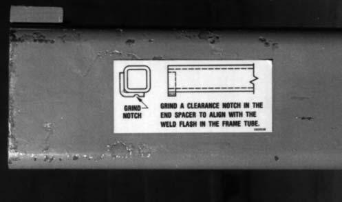
Mounting procedures for the single Axles or the Tandem Axle assemblies are essentially the same. NOTE: Before the Axle Extensions can be installed, a notch to match the inside weld flash location may have to be ground into the End Spacer of both Axle Extensions. A Decal, displaying this information is provided on the Extension.
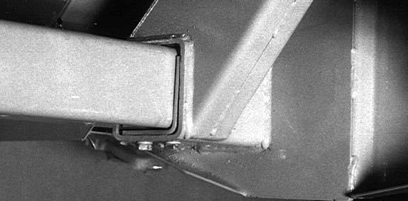
To install the Axle Extensions, carefully raise and properly block the Main Frame off the floor a sufficient amount to provide clearance to insert the Axles with mounted Wheels and Tires. BE SURE when the tires are mounted that the Valve Stems face out. The Wheels should be installed and secured with 90 lb–ft (125 Nm) torque. The Single Wheel Axle Extensions have Gussets on the ends that MUST be installed facing up. The Tandem Axle Spindle assemblies have Gussets on their top sides which MUST be installed facing up. For Single and Tandem Axle assemblies, BE SURE to install assembly labeled “Left” on the left side of the Harvester. Before an Axle Extension can be inserted into the Harvester Frame Tube on either side, the Angled Axle Spacers MUST be temporarily removed and then replaced after the Extensions are inserted. After the Spacers are secured, the Extensions should be secured with (1 each) 1/2 x 6″ CS, L and N.
NOTE: Refer to the Adjustments chapter for Spindle height and Wheel positioning details, if an Attachment is being mounted as part of this set-up and assembly procedure.

Step 3: Jack (Fig. 86)
Attach the Jack to the mating Hub on the Tongue. Swing the Jack down and lock it in the “Supporting” position with the Lockpin provided. Block the Wheels, in the front and back on both sides of the Harvester, and adjust the Jack to level the Tongue.
Step 4: Front Bearing Stand, Main Drive and Guards (Figs. 86 thru 89)
NOTE: The following mounting procedure is best accomplished by two setup people.
First, layout the components along side the Tongue and align them with regard to their appropriate direction and position of attachment.
Next, raise the entire Main Drive assembly up and rest it on top of the Tongue. Then, raise the back end of the Drive and slide it onto the Main Bevel Gearbox Shaft. Then, raise the front end of the Drive and place the Front Bearing Stand over the Drive Line while aligning the (12) Stand mounting holes with the holes in the Tongue. Secure the Stand to the Tongue with (12 each) 1/2 x 1″ CS and FLN.
Install shield bracket (at the back end of PTO shaft cover) to PTO shield support with supplied hardware. The hardware is pre–installed on the Shield Support on the Transmission. Secure hardware. See Fig. 88.

1 – PTO shield support on transmission
2 – Shield bracket
3 – 3/8x1-1/2″ Cap Screw (2)
4 – 3/8″ Flat Washer (2)
5 – 5/8″ Flat Washer (2) - Must be free to move
6 – Sleeve (2)
7 – 3/8 ″ Nylon Insert Lock Nut (2)
Fig. 88
It may be necessary to install the front Bearing Stand Guards and Hose & PTO Storage Support. Figure 89.
1 – Hose and PTO Storage Support
2 – 3/8 x 1-1/4″ Cap Screws & 3/8″ Lock Washers (4 ea)
3 – Right PTO Shield
4 – 3/8 x 1″ Cap Screws and 3/8″ Lock Washers and Flat Washers (3 each)
5 – Left PTO Shield
6 – 3/8 x 1″ Cap Screws (3 each)(w/Loctite or equiv.)
Fig. 89
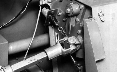
Step 5: Telescoping PTO Drive (Fig. 90)
NOTE: The Telescoping Drive Yoke and Main Drive Shaft Splines are manufactured to mate together in only one position.
Both the 1-3/8″ and 1-3/4″ telescoping PTO drives have spring loaded locking couplers on both ends of the drives. Clean and lightly grease the splines on the Main Drive PTO shaft, the Reversing PTO Drive Shaft and the Yoke of the Telescoping Drive. Depress the Safety Lock Ring and slide the Yoke onto the Main Drive PTO shaft. Move the Yoke back and forth until the Safety Lock Ring pops forward and locks into the groove in the PTO shaft.
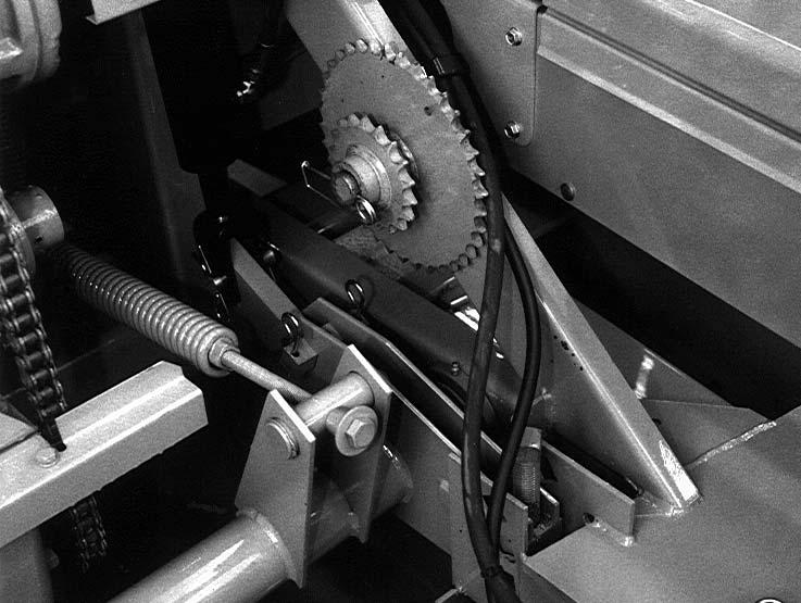
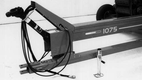
Step 6: Tongue Control Cylinder & Hoses (Optional)(Figs. 90, 91 & 92)
IMPORTANT: When routing the Hydraulic Hoses inside the Hose Side Cover, the Tongue should be swung out to the maximum left (opposite of Transport) position to assure an ample amount of Hose will be available at the rear of the Drive Line.
To install the Tongue Controls, proceed as follows:
1.Properly position and secure the Cylinder to the Tongue and Harvester Frame with a Cylinder Pin and two 3/16 x 1-1/2″ Cotter Pins on each end as shown.
1 – Main Drive PTO Shaft
2 – Reversing Shaft (for Knife Sharpener operation)
3 – PTO Locking Coupler (Both Ends)
4 – PTO Hitchpin Alignment Decal
5 – Lift Cylinder or Tongue Control Cylinder Hoses Secured to Right Side of Front Bearing Stand
6 – Wiring Harness Secured with Clamp to Either Hose Clamp
7 – Lift Cylinder or Tongue Control Cylinder Hoses Secured to Left Side of Front Bearing Stand
Fig. 90
1 – Hose and Wire Harnesses Entering Back end of Hose Side Cover
2 – Tongue Control Cylinder Base End Attached to Harvester Frame with Cylinder Pin Secured with (2) 3/16 x 1-1/2″ Cotter Pins
3 – Fitting of Tongue Control Cylinder Angled and Facing Rear of Harvester.


4 – Hose Clamp
5 – Length–of–cut Sprocket Storage
Fig. 91
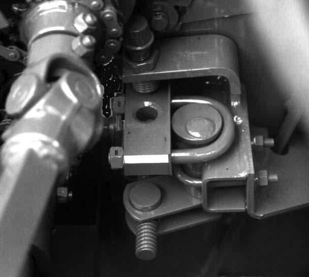
IMPORTANT: The Rod end of the Cylinder MUST be attached to the Harvester Tongue. The Cylinder Ports MUST face the right side of the Harvester.
2.Using a drop of Loctite (or equivalent hydraulic sealing compound) install a 90° Swivel Adapter Union into each of the Cylinder ports; one of the adapter unions has a built-in Restrictor. When correctly installed, the 90° fittings are to face toward the rear of the Harvester.
4.Install supplied Couplers to the ends of the Hoses.
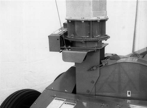
Step 7: Deflector, Cap and Controls (Figs. 93, 94, 95 & 96) CAUTION
For personal safety, because of the weight and awkwardness of the deflector (and extensions), it is best that at least two people perform the deflector mounting procedures.
NOTE: If the Harvester is to be set-up with mounted Vertical and/or Horizontal Extensions, refer to the Accessory Components topic, in this chapter, for mounting details.
Begin this assembly by first installing the Cap Spring (from the Toolbox) between the hole in the Cap and the Bracket on the Deflector (or Horizontal Extension).
1 – Rod End of Cylinder Attached to Tongue with Cylinder Pin Secured with (2) 3/16 x 1-1/2″ Cotter Pins
2 – Transport Pin and Lock Pin
3 – Cylinder Ports MUST Face Right Side of Harvester
Fig. 92
3.Remove the Top Cover from the Main Drive Line Shield. Install the Hoses to the Fittings on the Cylinder and route the Hoses from the Cylinder up to the rear of the Main Drive Shield passing through the grommeted hole in the front of the top Transmission Cover. Install a supplied Hose Clamp on the diagonal Brace near the Length–of–cut Sprocket storage area. Route Hoses along the Main Drive Line Shield and up under the Hose Holder on top of the Front Bearing Stand. Anchor the Hoses to the Hose Holder with the Double Hose Clamp. Reinstall the Top Cover onto the Main Drive Line Shield after the Wiring Harness and all of the Hoses are installed.

Remove the Deflector and its shipping parts from the Harvester Frame; discard the shipping parts.
Carefully raise and properly support the Deflector in the “rear delivery” position on top of the standard 6 inch Vertical Deflector Extension. Position the corners of the Deflector over the four gussets on the 6 inch Vertical Deflector Extension. Install eight 1/2 x 1-1/4″ CS through the Deflector and Extension. Secure each CS with a LN.
NOTE: Check that the Deflector is not binding before proceeding. If necessary, readjust the Clamps and Spacers. At this time also adjust the Tripod Brace and Arm (where applicable), to find the proper alignment for the Deflector (and Tripod) that best enables turning the Deflector with the least amount of resistance.
Mount the Angle Bracket to the side of the Deflector (or Horizontal Extension) using the hole provided. Secure the angle with a 5/16 x 3/4″ CS, L and N. Place the head of the CS inside the Deflector.
Temporarily remove the rear 1/2″ N, L and (1 of 2) P from the middle of the left side of the Deflector. Then, install a Pulley onto the smaller end of an S-Hook and squeeze the S-Hook shut. Install the larger end of the S-Hook over the 1/2″ CB and replace the P, L and N. The S-Hook should be between the two (2) P. The Pulley should be free to pivot.
1 – S-Hook & Pulley Assembly Mounted on 5/16 x 1-1/2″ THMS Secured with LN
2 – Deflector Pivot Mast
3 – S-Hook Pulley Assembly Mounted on Left Rear 1/2″ CB (S-Hook secured Between Deflector Pivot Mast and 1/2″ P with a 1/2″ L & N)

Fig. 96: Horizontally Extended Deflector

Form another S-Hook and Pulley assembly and install this onto the Cap. BE SURE to secure the S-Hook to the Cap and Pulley by squeezing the ends shut.
For a horizontally extended Deflector application, temporarily remove the LN from the 5/16 x 1-1/2″ THMS above the Deflector Brace on the left side. Then, place an S-Hook and Pulley assembly over the THMS and reinstall the LN; make sure the S-Hook pivots freely when the LN is tightened. Secure the S-Hook to the Bolt and Pulley by squeezing the ends shut.
Attach another S-Hook to the Angle Bracket attached on the left side of the Deflector (or Horizontal Extension). Squeeze both ends shut.
Insert the Cap Control Cable (Wire Rope) into the hole in the Cap Gearmotor Spool, from the outside of Flange, into the middle of the Spool (Fig. 94). Then, route the end of the Wire Rope up through the Pulleys and back to the S-Hook on the Angle Bracket as shown (Fig. 95). Form a loop over the end of the S-Hook and install a Wire Rope Clamp to secure the loop to the S-Hook. Cut off any excess Cable, extending beyond the Cable Clamp.
NOTE: The Wire Rope should be cut to length so there are NO wraps around the Spool when the Cap is in the raised position. Any wrapping on the Spool when the Cap is “up” will uncoil, and the Cable will jump off of the Spool.
Step 8: Implement Wiring Harness
(See Figs. 90 & 91)
The Main Implement Wiring Harness is the electrical connection between the tractor-mounted Control Box and the Harvester-mounted electrical components. The following information describes routing the Harness, making the appropriate Plug connections and Clamp locations for the Wiring Harness and Power Leads. Refer to the Wiring Diagrams provided in the Service chapter for additional identifications and proceed as follows:
IMPORTANT: When routing the Main Wiring Harness or the Hydraulic Hoses inside the Hose Side Cover, the Tongue should be swung out to the maximum left position to assure that an ample amount of Harness and Hoses is available at the rear end of the Drive Line.
Begin by routing the Main Wiring Harness inside the Hose Side Cover on the side of the Main Drive Line. Pass the Connector directly underneath the sloped portion of the Front Bearing Stand. Allow enough Harness to extend to the tractor-mounted Connector, while keeping the Harness above the Telescoping PTO Drive.
The Wiring Harness should be routed on the right side of the Stand. Install two 1-1/4″ size Wire Clamps around the Harness and fasten it to the top inside surface of the Front Bearing Stand with (2 each) 5/16 x 1″ CB-SN, L and N.
IMPORTANT: Do NOT install any Hoses between the top of the Harness and the underneath slope of the Front Bearing Stand. The weight of the Hoses could damage the Wire Harness. In addition, do NOT clamp the Implement Wiring Harness to any portion of the tractor. This will surely damage the Harness if the tractor moves away from a parked Harvester with the Wiring Harness still attached. ONLY use the electrical Connector to attach the Implement Harness to the Tractor Connector. The Connector has a “Breakaway” feature to prevent damage. For additional details, refer to the Control Box & Wiring Harness Mounting step at the end of this chapter. Store the excess Implement Harness inside the Hose Side Cover. Reinstall the Top Cover onto the Hose Side Cover after all of the Hoses and the Wiring Harness are installed.
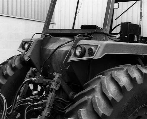
Step 9: Control Box Mounting & Wiring (Figs. 97 & 98)
Refer to Fig. 97 for a typical installation of a Control Box. Use your own judgement to select a conveniently reached mounting location on your particular tractor. Proceed as follows:
1.Select the desired Control Box mounting location in the tractor cab or on the fender. Using the Spade Mounting Bracket as a template, locate and drill the two 9/32” diameter holes. Then, secure the Bracket with (2 each) 1/4 x 1″ CS, P, L and N. Place the second Spade Mounting Bracket into the Receptacle on the back of the Box and temporarily install the Box onto the other attached Bracket in order to locate the two additional 9/32” diameter holes. Then, remove the Box, drill the holes and attach the second Spade Mounting Bracket.
NOTE: The two Spade Mounting Brackets can be bent, drilled, or otherwise modified to fit the tractor, as required.
IMPORTANT: Be sure to avoid sharp metal corners or objects and pinch points along the path of the Harness, which could cause insulation break down and a short-circuit.
2.Make the proper Red (+) and White (–) ring Terminal Power Supply Harness connections to the tractor battery or starter. The Harvester controls will NOT always operate as desired, if the Control Box wires are attached anywhere else except at the battery or tractor starter connections.
The battery MUST provide 12 volts D.C. The tractor MUST have a negative (–) ground. Route the Harness Plug to the Control Box.
1 – Control Wiring Harness on Tractor
2 – Control Box Mounted on Spade Mounting Bracket Secured to Fender Inside Tractor Cab (At Conveniently-reached Location)
3 – Control Wiring Harness Connector with “Breakaway” Feature Secured in Harness Mounting Bracket Secured with (2 each) 3/8 x 1″ CS, P, L & N (As Required) (Bracket can be Secured with a single CS, provided anchoring Surface is Rigid)
4 – Harvester Wiring Harness
Fig. 97
IMPORTANT: Before plugging the Power Supply Harness Plug into the Control Box Power Receptacle for the first time, BE SURE to have the Power Keyswitch Key in the “ON” position, but do NOT have the Implement Wiring Harness connected to the Control Box. If the Implement Wiring Harness is connected and the White (–) or Red (+) Power Supply Harness wires are incorrectly connected, a short circuit will be developed which would cause the wires inside the Control Box to overheat. If the Implement Wiring Harness is NOT connected, the Control Box Circuit Breaker will trip to indicate a Power Wiring problem.
3.After the Power Wiring connection is properly made and tested, turn the Control Box Power Keyswitch OFF and remove the Key. Then, select a convenient path to route the Control Wiring Harness from the Control Box to the back of the tractor.
1 – Control Harness or Optional Long Control Harness
2 – Electrical Control Box
3 – Power Supply Harness
4 – Spade Mounting Brackets (2)
5 – Control Harness Mounting Bracket
Fig. 98: Control Box & Wiring Connections
4.Attach the Control Mounting Bracket using fieldsupplied holes in the back of the tractor. Secure the Bracket with (2 each) 3/8 x 1″ CS, P, L and N. The Bracket MUST be securely mounted so that the electrical connection is near the center of the tractor, parallel to the ground, and facing straight back toward the Harvester.
IMPORTANT: The flat part of the “D-shaped” hole should be on top when the Bracket is installed. If the Connector is NOT properly and securely mounted, its “breakaway” feature may NOT work. This could cause damage to the Connector and the Wiring Harnesses.
5.Remove the Special Nut and Lock Washer from the Control Harness Connector and retain these parts. Then, insert the Control Harness Connector into the “D-shaped” hole in the Mounting Bracket. Carefully, tighten the Special Nut and Lock Washer to secure the Control Harness Connector.
6.Route the Control Harness to the Control Box and connect the two (2) Plugs. Connect the 8-way Plugs to each other and the 3-way Plugs to each other. Do NOT cross-connect the Plugs.
Accessory Components
NOTE: The following components are customer–selected accessories which may be dealer–installed during the regular set-up and assembly procedures, or customer–performed procedures.

Step A: Tripod Kit
(Figs. 99, 100, 101, & 102)
The Tripod Kit is required with the 3-1/2 or 5-1/2-ft Horizontal Deflector Extension packages. It is also available whenever additional Deflector support is desired and required when more than 2 feet of Vertical Extensions are going to be installed.
NOTE: If Extensions are going to be used, they MUST be attached to the Deflector before the Tripod Kit is mounted. The Tripod Kit will work with 0 to 2 feet and 3 to 4 feet of vertical extensions. The Kit will NOT fit with 2-1/2 feet of vertical extensions.
Caution
For personal safety, because of the weight and awkwardness of the extended deflector, at least two people should perform the deflector mounting procedures.
With the desired Deflector Extension(s) mounted onto the Deflector, proceed to mount the Tripod Kit as follows:
1.Properly position and secure the Tripod to the top of the Lift Cylinder Post with (4 each) 3/8 x 1-1/4 CS, L and N. When correctly positioned, the Vertical Tube of the Tripod should be facing towards the rear of the Post.
2.Preassemble (6 each) 5/8 x 1-1/2 CS and N into the welded-on Nuts on the Tripod Arm and Tripod Bracket.
3.Based on the number of feet of Vertical Extensions to be used, determine the position and direction of the Tripod Arm with respect to the Tripod Bracket. Referring to the illustrations provided, position the Arm below the Bracket for 1 or 2 feet of Vertical Extensions. For 3 or 4 feet of Vertical Extensions, the Arm MUST be positioned above the Bracket. In addition, for 3 feet of Vertical Extensions, the Arm MUST positioned with the extended Hub facing up. For 4 feet of Vertical Extensions, the Arm MUST be turned around and be facing down. On the basis of the above determina- tion, install the Tripod Arm and Tripod Bracket over the Tripod Tube in the required position.
4.Align the Tripod Bracket so that its mounting holes line up with appropriate holes in the Tripod Tube in the required position. The slotted ear MUST face the front of the Harvester. Secure the Tripod Bracket with (2 each) 1/2 x 3-1/2″ CS and LN. Also, secure the Tripod Bracket by tightening the (2) 5/8 x 1-1/2″ CS and the (2) 5/8″ N to lock the positions of the CS.
5.Loosely attach the bottom end of the Front Tripod Brace to the Tongue Cylinder Bracket. Install a 5/8 x 3″ CS through the Frame, the thick end of the Tripod Anchor and the Tripod Brace. Secure the assembly with a 5/8″ L and N.

6.Loosely attach the Right Tripod Brace to the Axle Bracket with a 5/8 x 1-3/4″ CS, L and N.
10.Properly position and attach the Spout Pivot Bracket onto the Spout using the upper Spout Bracket mounting holes and existing holes and hardware in the Spout. BE SURE to delete the (4) 5/8″ P from the Spout Carriage Bolts when installing the Bracket.
NOTE: The following procedure can only be carried-out after the Spout is in position to be installed and secured onto the Blower Outlet.
11.Install the Spacer into the hole in the Spout Bracket and position the Bracket between the plates of the Tripod Arm. Install a 1/2 x 3-3/4″ through the Arm. Secure the 1/2″ CS with a LN.
NOTE: To facilitate Tripod adjustment, rotate the Spout so that it is in-line with the Tripod Arm.
12.After the Spout (with mounted Extensions) is properly secured onto the Blower Outlet, the Tripod Arm can be adjusted (up or down) to position the Spout Bracket midway between the plates of the Tripod Arm. Once the Arm is centered, it can be secured to the Tripod by tightening the (4) CS and the (4) 5/8″ N can be tightened to lock the positions of the CS. Proper attachment of the Tripod Arm accomplishes the side-to-side alignment of the Tripod. Forward and backward alignment of the Tripod is accomplished by forcing up on the Cap end of the Spout and tightening the Clamp and front Tripod Brace connection to the Tripod Bracket. If the limit of the slot in the Bracket is reached before correct Tripod and Spout alignment can be obtained, (1 of the 2) 5/8 x 1-3/4″ CS should be temporarily removed and repositioned through the other hole in the Brace, after the Clamp is rotated.
Step B: Tripod Extension (Fig. 102)
8.Loosely
The Tripod Extension MUST be ordered separately and installed whenever the Deflector is raised between 3 and 4 feet; including the height of the factory-installed 6 inch Vertical Extension. A total of 2-1/2 feet of vertical extension will NOT fit the Tripod Kit. The Extension is attached into the top of the Vertical Tripod Pipe and secured with two 1/2 x 4″ CS and four 1/2″ N. Once the Tripod Extension is securely attached, the Tripod Arm can be installed in the same way as attaching it to the Vertical Tripod Pipe.
Step C: Vertical Extensions (Fig. 102)
The CB1075 Harvester is provided with a factoryinstalled, 6 inch Vertical Extension. This allows the Capmotor and Deflector Control Motors to be factory installed and pre-wired. When additional 6 inch, 1 foot, or 2 foot Vertical Extensions are installed, they should be installed above the factory installed 6 inch Extension. A set of (eight each) 1/2 x 1-1/4″ CS and LN is provided with each Extension for attaching that Extension.
Step D: Horizontal Extensions (Fig. 102)
Mounting procedures for either the 3-1/2-ft or 5-1/2-ft Horizontal Deflector Extension packages are the same. Refer to the Tripod Kit mounting procedures, after the Extension is attached to the Deflector. To mount either Extension, proceed as follows:
1.Remove and retain the Clean-out Cover(s).
2.Remove the Cap and attaching hardware from the Deflector and reinstall these same parts onto the end of the Extension.
NOTE: Throughout this assembly procedure, BE SURE to install all attaching hardware from inside the Deflector or Extension so that all bolt heads are located on the inside.
3.Attach and loosely fasten the Horizontal Extension Brackets to each side of the Extension with (three each side) 5/16 x 3/4″ THMS, L and N.
4.Slide the Extension with Brackets over the end of the Deflector and loosely secure the Brackets to the Deflector with (one each side) 5/16 x 3/4″ THMS, P, L and N.
5.Install and loosely attach one 5/16 x 1-1/2″ THMS into the left lower rear hole in the Deflector and Extension Bracket. Install THMS through Deflector, through Extension Bracket, through Extension and secure it with two P, a L, N and a LN.
6.Install and loosely fasten a 5/16 x 1″ THMS in the remaining three holes with L and N.
7.Attach and loosely fasten the Extension Deflector Tie to the Deflector and Extension using (four each) 1/4 x 1/2″ THMS, L and N.
8.Properly position and install the Deflector Extension Brace between the Deflector Flange and the Extension Brackets. Loosely attach the top end of the Brace to the Extension Brackets with (two each side) 1/2 x 1-1/4″ CS, P, L and N as shown. Mount the bottom end of the Brace to the Deflector Flange and Vertical Extension Flange or Deflector Clamps with (two each) 1/2 x 5″ CS and attaching hardware.
11 – Factory Installed 1-foot Vertical Spout Extension & Cap Control Motor
9.Make sure that the inside top end of the Horizontal Extension is slightly above the inside top end of the Deflector, in the area where the two parts meet. Likewise, make sure that the Cap end of the Extension is down and properly in line (to provide a good radius) for smooth material flow against the tops of the Deflector and Extension, as the material is being discharged. Once the correct alignment is obtained, all loosely attached mounting hardware can be tightly secured.
10.Relocate Cap Motor from behind Blower Outlet onto front of Deflector per instructions provided with Deflector Extension Brace.
Step H: Safety Chain
NOTE: Route and anchor an accessory 30,000 Pound Safety Chain Kit as shown in Transporting chapter.
Step J: Second Tractor Control Box Wiring Kit
The accessory Second Tractor Control Box Wiring Kit is available for adapting the same Control Box to a second tractor. The Kit contains a Power Supply Harness, a Control Harness, a Control Harness Mounting Bracket and two Control Box Mounting Plates. Refer to Control Box Mounting and Wiring procedures for comparable installation details.
CHAPTER 15 OPTIONAL FEATURES & ACCESSORIES
Most of the optional features & accessories, listed in this chapter, are covered by information listed in the Set-up & Assembly chapter. Some accessories are shipped with separate instructions to install. Refer to your Gehl “Farm Equipment Suggested List Prices” for stock numbers and ordering information.
AXLES, WHEELS & TIRES
The Harvester can be obtained with several choices of Axles, Wheels and Tires. The various choices are:
1.Single Axle Set with two 14 x 8.00 DC Wheels (less tires)(NOT FOR USE WITH CROP PROCESSOR ATTACHMENT).
2.Single Axle Set with two 11L x 14 6–ply rating Implement Tires (NOT FOR USE WITH CROP PROCESSOR ATTACHMENT).
3.Single Axle Set with two 10.00–20 12–ply rating recapped truck tires with ribbed implement tread.
4.Single Axle Set with two 16.5L–16.1 8–ply rating Implement Tires.
5.Tandem Axle Set with four 11L–15 8–ply rating Implement Tires.
Hydraulic Tongue Kit
A Hydraulic Tongue Kit is available to remotely adjust the Tongue position from the tractor seat. The Kit contains a standard double-acting Cylinder, two Hose assemblies, two Cylinder Anchor Pins, two Adapter Unions, two male Couplers, a Notch Cover and appropriate attaching hardware. Mounting details are provided in the Set-up & Assembly chapter. This Kit requires a second pair of tractor hydraulic outlets.
Blower Rim Sheet Liner
The Harvester is designed with a replaceable Wear Liner for the Blower Rim Sheet. A replacement Liner is available by part number 094948. Instructions for installation are included with the Kit of parts.
5 ft LONG CONTROL BOX HARNESS
A 5 foot Control Harness is available for Shear Bolt units, if the Control Harness cannot reach the Control
Box. Installation information is provided in the Set-up & Assembly chapter.
15 ft LONG CONTROL BOX HARNESS
A 15 foot Control Harness is available for Metal Detector units, if the Control Harness cannot reach the Control Box. Installation information is provided in the Set-up & Assembly chapter.
DEFLECTOR EXTENSIONS & COMPONENTS
The Harvester is shipped from the factory with a 6 inch Vertical Deflector Extension factory-installed onto the Blower Outlet. This enables factory-installation of both the Deflector and Cap Control Motors. Several Kits are available singly or in combination for relocating the effective position of the Cap, higher, lower or farther away from the Blower Outlet. The following information defines the various Kits which are available:
Vertical Extensions
Vertical Deflector Extensions are available in 6 inch, 1 foot and 2 foot sizes. A maximum of 4 feet of vertical Extensions can be installed. A Tripod Kit is required when a total of more than 2 feet of Vertical Extensions is installed. The Tripod will NOT accept 2-1/2 feet of Vertical Extensions.
Horizontal Extensions
Horizontal Deflector Extensions are available in 3-1/2 foot and 5-1/2 foot lengths. Both Kits contain all of the same components and the appropriate 3-1/2 foot and 5-1/2 foot long Extension. A Tripod Kit is required.
Tripod Kit
The Deflector Tripod Kit is available when additional Deflector Support is desired or needed.
Tripod Extension
The Tripod Extension is available and required whenever the Deflector is raised more than 2 feet. The Tripod Extension Kit contains the Extension and attaching hardware. It can be used with 3 to 4 feet of vertical extension, but 2-1/2 feet of vertical extension will NOT fit.
Deflector Liner
The Harvester is designed with a replaceable Wear Liner for the Deflector. A replacement Liner is available by part number 112182. Installation details are provided in the Service chapter.
Main Drive Shear Bolts
Replacement 5/16 x 2″, Grade 8 Shear Bolts and Lock Nuts are available by GEHL part number 153753. One package contains eight Bolts and eight Lock Nuts.
Auger Drive Shear Bolts
Replacement 1/4 x 1″, Grade 5 Shear Bolts and Lock Nuts are available by GEHL part number 904400 One package contains eight Bolts and eight Lock Nuts.
Feed Roll Shear Bolts
Replacement 1/4″ x 1-1/2″, Grade 8 Shear Bolts and Lock Nuts are available by GEHL part number 080079. One package contains eight Bolts and eight Lock Nuts.
Safety Chain
NOTE: If the Harvester is going to be transported on a public highway, a Safety Chain should be obtained and installed per details in the Transporting chapter.
A 30,000 Pound Safety Chain Kit is available to accommodate the potential weight of the Harvester and a forage box.
Second Tractor Control Box Wiring Kit
A second Tractor Control Box Wiring Kit is available for adapting the same Control Box to a second tractor. Installation information is provided in the Set-up & Assembly chapter.
Telescoping Pto Drives
The Harvester can be ordered and obtained with either a 1-3/8″ or a 1-3/4″ Telescoping PTO Drive.
4 ″ QUICK ATTACH HITCH EXTENSION
A 4″ Quick Attach Hitch Extension is available for tractors without an extendable drawbar to reach the 21″ PTO locking ring groove to hitch pin dimension.
Transport Lighting
A Transport Light Kit is available for use on public highways. Installation Instructions are included with the Kit.
Cp1000 Crop Processor
A Crop Processor is available for the CB1075 Harvester. The Kit includes a storage carriage.
Chapter 16 Decal Locations
General Information
Decal location information is provided to assist in the proper selection and application of new decals, in the event the original decals become damaged or the machine is repainted. Refer to the listing for the illustration reference number, part number, description and quantity of each decal provided in the Kit. Refer to the appropriate illustrations for replacement locations.
To insure proper selection of the correct replacement decals, compare all of the various closeup location drawings to your machine before starting to refinish the unit. Then circle each shown decal (applicable to your machine) while checking off its part number in the listing. After you have verified all the decals needed for replacement, place any extra unnecessary decals aside for disposal.
NOTE: Refer to the SAFETY Chapter of the Operator’s Manual for the specific information provided on all of the various Safety Decals furnished in the Decal Kit(s).
New Decal Application
Surfaces MUST be free from dirt, dust, grease and other foreign material before applying the new Decal. To apply, remove the smaller portion of the decal backing paper and apply this part of the exposed adhesive backing to the clean surface while maintaining proper position and alignment. Peel the other portion of the backing paper off slowly while applying hand pressure to smooth out the Decal surface.
Caution
ALWAYS follow safety precautions on decals. Replace the decals if they are damaged, or if the unit is repainted. If repainting, BE SURE that all applicable decals are affixed to your unit.
Paint Notice
Use this list to order paint for refinishing:
906315One Gal. AG Red
902872One Qt. Light Grey
9063166 (12 oz. Spray Cans) AG Red
9028746 (12 oz. Spray Cans) Light Grey
The Decal Set Number for the CB1075 is 145618. The Set includes the following:
Ref.Part
No.No.Description & Quantity
1080247NO Step
2091444DANGER - Rotating Drive Line
3093020Lubrication Symbol (12 Places)
4093202DANGER - Avoid Electrocution
5093209Place Edge
6093211Cutterbar Removal & Replacement
7093365WARNING - Close or Replace Guard (3 Places)
8093366IMPORTANT - Store Manual Here
9093367WARNING - Owner’s Responsibility & Read Manual
10093373WARNING - General Safety
11093374WARNING - Towing Implement Without Brakes
12093376WARNING - Keep Hands Out
13093378DANGER - Rotating Components (2 Places)
14093379WARNING - Wear Goggles When Using Knife Sharpener
15093381WARNING - Use Drawbar Transport Lock
16093653WARNING - Rotating Drive Line
17094502*Notice (Not Shown)
18094503*DANGER - Crusher Roll (Not Shown)
19094912Colorbar 12″
20094914GEHL 5 x 23-1/2″
21094951Made in USA
22113181Auto-Max
23120399DANGER - Auger
24122617GEHL
25126345GEHL 2-1/2 x 11-3/4″
26126757Stripe - 3/4 x 10′ Roll
27143007 DANGER - Shield Missing
28145048*Crop Processor (Not Shown)
29145216Red Reflector Strip (2 Places)
30145217Amber Reflector (2 Places)
31145218Orange Marker (2 Places)
32145316Length Of Cut Chart
33145847Knife Sharpener Instructions
34153759Shearbar Adjustment
35153761Shearbolt
361537991000 RPM
371540881075
38154226CAUTION - Hitchpin alignment
39154281*Belt Routing (Not Shown)
* CP1000 only
Not included in Decal Kit
NOTE: The Decal List has been duplicated for your convenience when selecting Decals from the following page.
The Decal Set Number for the CB1075 is 145618. The Set includes the following:
Ref.Part
No.No.Description & Quantity
1080247NO Step
2091444DANGER - Rotating Drive Line
3093020Lubrication Symbol (12 Places)
4093202DANGER - Avoid Electrocution
5093209Place Edge
6093211Cutterbar Removal & Replacement
7093365WARNING - Close or Replace Guard (3 Places)
8093366IMPORTANT - Store Manual Here
9093367WARNING - Owner’s Responsibility & Read Manual
10093373WARNING - General Safety
11093374WARNING - Towing Implement Without Brakes
12093376WARNING - Keep Hands Out
13093378DANGER - Rotating Components (2 Places)
14093379WARNING - Wear Goggles When Using Knife Sharpener
15093381WARNING - Use Drawbar Transport Lock
16093653WARNING - Rotating Drive Line
17094502*Notice (Not Shown)
18094503*DANGER - Crusher Roll (Not Shown)
19094912Colorbar 12″
20094914GEHL 5 x 23-1/2″
21094951Made in USA
22113181Auto-Max
23120399DANGER - Auger
24122617GEHL
25126345GEHL 2-1/2 x 11-3/4″
26126757Stripe - 3/4 x 10′ Roll
27143007
DANGER - Shield Missing
28145048*Crop Processor (Not Shown)
29145216Red Reflector Strip (2 Places)
30145217Amber Reflector (2 Places)
31145218Orange Marker (2 Places)
32145316Length Of Cut Chart
33145847Knife Sharpener Instructions
34153759Shearbar Adjustment
35153761Shearbolt
361537991000 RPM
371540881075
38154226CAUTION - Hitchpin alignment
39154281*Belt Routing (Not Shown)
* CP1000 only
Not included in Decal Kit
Numbers
4” Quick Attach Drawbar Extension, Installation, 81
Accessory Components, Set–up & Assembly, 109 Adjustments, 38–55
Ammonia silage additive use, 57
Attachment positioning, 19
Attachment positioning adjustments, 38
Axles & Wheels, 38
Downstop, 38
Lift height, 38
Lift Spring, 39
Auger, troubleshooting, 99
Auger Drive Chain service, 71
Axles, Wheels and Tires installation, 102
Bevel Gearbox service, 62
Blower, troubleshooting, 87
Blower Adjustments, 39
Belt Idler, 39
Drive Belt, 40
Fan Paddles, 40
Blower service
Drive Belt, 62
Drive Sheave, 62
Driven Sheave, 62
Rim Sheet Wear Liner, 63
Cap control, 19
Chain & Sprocket service, 64
Chain Drives, troubleshooting, 89
Chain length table, 83
Checklists, delivery, 5–7
Control Box mounting and wiring, 107
Controls & Safety Equipment, 19–23
Crop Processor, troubleshooting, 100
Crop Processor Roller Mill, 22, 24 adjustments, 45
Cutting Cylinder, troubleshooting, 88
Cutting Mechanism service
Knife replacement, 68
Shear Bar, 64
Index
Decal Locations, 116–121
Deflector, troubleshooting, 89
Deflector adjustments, 42
Deflector control, 19
Deflector service, 70
Deflector, Cap and Controls installation, 105
Drive Chains adjustment
Attachment Driver, 44
Auger Drive Chain, 44
Length–of–Cut, 44
Lower Feed Rolls, 44
Shifter Transmission, 44
Upper Feed Rolls, 45
Drive Chains lubrication, 57
Electric Clutch Reburnishing, 73
Electric controls service, 72
Emergency Shutdown, 24
Entering the crop, 25
Feed Roll Spring tension adjustment, 45
Feed Rolls & Attachment Controls all Harvester models, troubleshooting, 89
Torque Sensor models ONLY, troubleshooting, 90
Field Operation, troubleshooting, 92
Front Bearing Stand, Main Drive and Guards installation, 103
General operating information, 24
Grease Fitting locations, 58
Greasing, 57
Guards & Shields, 20
Harvester–Attachment alignment, 82
Hitchjack, 21
Horizontal Extension installation, 111
Hydraulic circuit requirements, 57
Identification numbers, 3
Implement Drive Line Guards, 20
Inflation pressures. See Tire pressures Introduction, 2
Jack. See Hitchjack Jack installation, 103
Knife Sharpener, 22 troubleshooting, 93
Knife Sharpening
Cylinder Knife sharpening, 69
General information, 68
Preparing Sharpener, 68
Ratchet Pawl, 70
Ratchet Wheel tension, 70
Sharpener Carriage Rails, 70
Stone replacement, 70 Knives adjustment, 46
Leaving the crop, 25
Length–of–Cut adjustment, 47
Lift System, troubleshooting, 93
Lift System Lock, 19
Lift System lock for transport, 84
Lubrication, 56–61
Maintenance, 122–123
Mandatory Safety Shutdown Procedure, 8
Metal Detector
Bypassing the Metal Detector system, 33
Daily system inspections, 34
General information, 31
Introductory information, 30
Metal detection, 32
Stopping Harvester, 32
System detection reaction procedure, 32
System Start–up, 31
System start–up & reset procedure, 32
System test, 34
Metal Detector model, Control Box, 26
Metal Stop, troubleshooting, 94
Metal Stop Solenoid & Stop Pawl adjustment, 48
Miscellaneous Guards, 21
Model & Serial No. Plates, 2
Oiling, 57
Operating Feed Rolls and Attachment, 25
Operation, 24–37
Operator’s Manual, storing, 2
Optional Equipment & Accessories
15 ft Long Control Box Harness, 114
4 inch Hitch Extension, 115
5 ft Long Control Box Harness, 114
Axles, Wheels & Tires, 114
Blower Rim Sheet Liner, 114
CP1200 Crop Processor, 115
Deflector Extensions & Components, 114
Deflector Liner, 115
Horizontal Extensions, 114
Hydraulically Adjustable Tongue, 114
Safety Chain, 115
Second tractor Control Box Wiring Kit, 115
Shear Bolts
Auger Drive, 115
Feed roll, 115
Main Drive, 115
Telescoping PTO Drives, 115
Transport Lighting, 115
Tripod Extension, 114
Tripod Kit, 114
Vertical Extensions, 114
Optional Features & Accessories, 114
Overload Protection, 22
Overload protection
Control Box, 29
Lower Feed Rolls, 28, 29
Main Drive Line, 28
Parts Manual, storing, 2
Preparing For Field Operation, 80–83
Preparing Harvester for operation, 82
Protection of unpainted surfaces, 86
PTO Drive, troubleshooting, 99
Reburnishing Electric Clutch, 73
Remote Grease Lines, 71
Rim Sheet Nut torque, 64
Roller Mill adjustments
Drive Belt tension, 46 minimum Roll spacing, 45
Roll alignment, 45
Roll spacing, 45