35 minute read
METAL DETECTOR

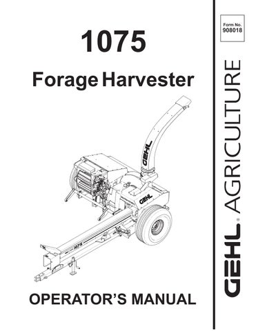
INTRODUCTION (Fig. 17)
The Metal Detector contains a Metal Stop System which is designed to prevent ferrous (containing iron) metal objects from entering the Forage Harvester Cutting Cylinder. It can be used with all approved mounted Attachments.
When a ferrous metal object passes through the Magnetic Field over the Lower Front Feed Roll, a low voltage signal is sent to the Amplifier Box which is mounted on top of the Feed Roll Housing. When the signal reaches the Amplifier Box, an electrical contact is opened which, in turn, interrupts power to the Pawl Solenoid. The Feed Rolls are stopped immediately by the Stop Pawl. At the same time, the Electric Clutch opens to stop power to the Attachment and Feed Rolls.
When the Metal Stop System is functioning properly, the following ferrous metal objects can be detected: hitchpins scrap iron bolts wrenches rake teeth steel pipe steel fence posts plow points sickle sections chains nails wire rocks containing iron
Regardless of system adjustment, the following objects will NOT be detected: aluminum stainless steel wood tile cement stones
NOTE: The optimum performance of your Metal Stop System depends on it being kept in proper operating condition and properly maintained. Like any other electrical system, the Metal Stop System is subject to malfunction due to defects, occasional breakdowns, misuse and human error. As with any mechanical device, components can breakdown or wear. Therefore, it is highly recommended that the system be tested daily.
The Metal Stop System is only sensitive to moving objects; keep this in mind when performing the test procedures. There is also an area, at the center and the ends of the lower Feed Roll, where sensitivity is reduced. Sensitivity also decreases as the distance from the object to the Lower Front Feed Roll increases. During normal operation, a high detection rate is achieved because of the forces of gravity and the stirring action of the feeding mechanism which causes most of the ferrous metal objects to descend to the bottom of the incoming crop material.
As with all Gehl equipment, the Metal Stop System is initially warranted against defects in material and workmanship. However, because of the above described conditions, the Metal Stop System CANNOT and MUST NOT be expected to be 100% effective at detecting ferrous metal objects.
General Information
(See Fig. 13)
The Metal Stop System is operated from the tractor seat with the Harvester Control Box. A ferrous metal detection causes Amber Signal Light on the Harvester to “flash” and the Control Box Buzzer to sound.
NOTE: Sounding of the Control Box Buzzer also signals maximum capacity or “low speed”. The flashing Amber Light only signals for a metal detection. The Harvester can NOT be operated until after the Metal Stop System is reset.
To turn off the signaling devices, safely locate and remove the metal and, restore the detection system to be able to resume harvesting, perform the steps in the sequence given on the Control Box Decal or detailed in the Safety chapter.
SYSTEM START-UP
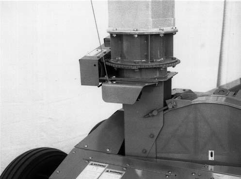
(Figs. 18 & 19 & see Fig. 13)
To initially start-up the Metal Stop System or reset it, after metal has been detected and removed, perform the “Start-up or Reset Procedure” given, with the tractor PTO disengaged.

If the Amber Light on the Harvester does NOT go out and remain “off”, the Stop Pawl is probably stuck in the Ratchet Wheel, as shown in the illustration provided. When the Pawl sticks, it causes the Circuit Breaker in the amplifier Box to open.
Wait about 10 to 15 seconds for the (heat activated) Breaker to cool. Then, idle the tractor, engage the PTO and reverse the Feed Rolls until the Rolls move. The Amber Light should go out and remain “off”. Now the Metal Stop System is ready to use. After the preceding steps are performed, idle the tractor, engage the PTO and start (resume) harvesting.
NOTE: The Harvester will NOT operate with the Control Box FEED ROLL Switch in the “Forward” position while the Amber Light on the Harvester is flashing. If, after attempting to reset system, the Amber Light does NOT remain “OFF,” refer to appropriate information in Troubleshooting chapter.
Action
Start-up or System Reset Procedure
Reason
1.Move Mode Switch to AUTO and leave it there. Metal Stop System does NOT operate with Mode Switch in MANUAL position. Refer to System Bypass topic in this chapter.
2.Move the FEED ROLL Switch to “Neutral.” If the Switch is in “Forward”, Buzzer will sound when Keyswitch is turned “ON”.
3.Turn Keyswitch “ON.” Control Box is energized and ready but, Amber Light goes “ON.”
4.Move the FEED ROLL Switch to “Reverse” position and momentarily activate the HOLD FOR REVERSE Switch (Harvester Amber Light will go off).
Stopping Harvester
The Harvester and Metal Stop System should be switched OFF when the Harvester is NOT being used. This will avoid unnecessary drain on the tractor battery. The following sequence should be carried out to turn the system OFF:
1.Move the Control Box FEED ROLL Switch to the “Neutral” position.
Action
Metal Stop System is set (reset) and ready for operation when the Amber Light is “OFF.”
2.Turn the Power Keyswitch to “OFF” and remove the Key before leaving the tractor seat.
Detection
When a ferrous metal detection occurs, the Solenoid will release the Spring-loaded Stop Pawl into the Ratchet Wheel. Simultaneously, the Electric Clutch will receive a signal to open, and thus, immediately stop the Feed Rolls and Attachment.
Detection Reaction Procedure
1.Move FEED ROLL Switch to “Neutral.” This stops the Buzzer.
Reason
2.Stop forward travel and back-up the tractor. This separates crop in the Feed Rolls from the crop on the ground.
3.Reverse the Feed Rolls. This removes the crop (containing the metal) from the Feed Rolls.
4.Shut-off the tractor PTO and engine. This keeps the Harvester from running unnecessarily.
5.Shut OFF the Power Keyswitch, remove the Key and take it with you.
6.Wait for ALL parts to STOP moving.
To prevent undesired or unexpected system activation.
To avoid being injured by moving parts.
7.Remove the metal from the crop. This should be done with the portion of the crop containing the metal on the ground.
The preceding action also occurs when the Mode Selection Switch is turned “OFF” as well as when Power is interrupted to the Metal Stop System.
A ferrous metal detection is indicated by the Amber Light on the Harvester flashing and the Control Box
Buzzer sounding. If the Amber Light is NOT flashing, the Control Box Buzzer is indicating a Torque Sensor or Speed Monitor activation.
When a ferrous metal detection occurs, carry-out the procedure detailed in the “Detection Reaction Procedure” given.

Warning
BEFORE searching for detected metal, exercise the MANDATORY SAFETY SHUTDOWN PROCEDURE (page 8). REMEMBER also that, when PTO is engaged, cylinder and blower continue to rotate when feed rolls and attachment are stopped.
The ferrous metal object will usually be within 1 foot of the end of the crop which was about to enter the Cutting Cylinder. If the metal object CANNOT be discovered through an initial search, continue the search after exercising the proper precautions in the following manner: a.Stop forward travel and back up the tractor b.Reverse the Feed Rolls c.Shut off the tractor PTO and engine d.Shut the Power Keyswitch “Off”, remove the Key and take it with you e.Wait for ALL parts to stop moving f.Remove the metal from the crop
1.Take the hay that was reversed out of the Hay Attachment and spread it onto the ground in front of the Attachment.
2.With NO one near the Harvester, reset the Metal Detector system and start-up the Harvester. Slowly move forward and harvest the windrow.
3.The ferrous metal object should be detected a second time.
4.Repeat the following standard procedure to remove the metal.
Warning
NEVER hand feed crop into the feed rolls, because the crop will feed faster than you can react to let go.
Making a hand–made windrow and driving slowly into it should drastically reduce the amount of material that has to be searched. The small amount of material going into the Feed Rolls should also make the second detection more likely to occur.
However, it is possible that the metal object stayed on the ground when harvesting the hand–made windrow or during the search.
The Metal Detector system resets itself when the Feed Rolls are reversed to remove the detected ferrous metal. The Metal Stop System sometimes may also detect metal while the Feed Rolls are being run in reverse. This type of metal detection will cause the Amber Light, on top of the Harvester Feed Roll Drive Frame, to continue flashing. Reset the system by shifting to reverse to make the Light go off.
BYPASSING THE METAL DETECTOR SYSTEM (Figs. 20 & 21)
Reasons Why
The Metal Detector system CANNOT be used with the Harvester Control Box Mode Selector Switch in the “OFF-MANUAL” position. The “OFF-MANUAL” position” mode cancels ALL automatic Shut-off Devices of the Harvester’s electrical system, including the Metal Stop System.
It may be desirable or otherwise necessary to bypass the Metal Stop System for the reasons mentioned in the previous paragraph or, if a malfunction occurs that CANNOT be remedied quickly. After the Metal Detec- tor system is bypassed, the Harvester can be operated in the same manner as a unit without the Metal Detector system. Bypassing the system allows you to operate in either the “OFF-MANUAL” or “AUTOmatic” mode.
1.Check the Wiring Harnesses, Wires and Plugs to determine their condition and electrical continuity.
2.Check the Stop Solenoid for correct adjustment and proper Ring alignment.
3.Check that the Metal Stop System is operating properly by carrying out the following “System Test” procedures.
System Test
Warning
BEFORE testing or adjusting the Metal Detector system, exercise the MANDATORY SAFETY SHUTDOWN PROCEDURE (page 8).
1.Unplug the Speed Monitor.
2.With the Mode Switch in “AUTOmatic”:
Procedure
To bypass the Metal Detector system, refer to the illustrations provided and proceed as follows:
1.Move the Pawl Spring from the “Operating” position to the “bypassed” position, as shown. After the Spring is moved, make sure that the Stop Pawl is away from the Ratchet Wheel.
2.Disconnect the Plug inside the Feed Roll Drive Frame, as shown. Using electrical tape, cover the ends of the Plugs to keep foreign material and moisture out of the Plug sockets. Also, fasten disconnected Plugs where they CANNOT rub on Upper Feed Roll Drive Shaft.
To restore the Metal Detector system, return the Spring and Plugs to their original operating positions and return the Control Box Switch to the “AUTOmatic” mode.
Daily System Inspections
(See Figs. 13 & 18)
Since the Metal Stop System is factory installed, the unit has been checked for proper operation before leaving the factory. The following inspections should be made on a periodic basis to maintain proper operation: a.Move the FEED ROLL Switch to “NEUTRAL”. b.Turn Control Box Keyswitch “ON”. c.Move the FEED ROLL Selector Switch to the “REVERSE” position and momentarily activate the “HOLD FOR REVERSE” Switch. Harvester Amber Light will go off unless the Pawl is stuck in the Ratchet Wheel. d.Move the FEED ROLL Selector Switch to the “FORWARD” position. e.Pass a ferrous metal object between the Upper and Lower Front Feed Rolls (the Solenoid should release the Stop Pawl into the Ratchet Wheel, the Amber Light should flash and, the Control Box Buzzer should sound signifying a metal detection).
3.If the Pawl is stuck in the Ratchet Wheel or the system fails to operate in the manner described, refer to the Troubleshooting chapter of this, manual, to determine the cause and remedy for the problem(s).
4.Reconnect the Speed Monitor to the Harvester Electrical Harness.
HARVESTER WITH SHEAR BOLT-PROTECTED FEED ROLL & ATTACHMENT DRIVES
OPERATING FEED ROLLS & ATTACHMENT (Fig. 23)
The Electric Clutch and Shifter Transmission combination is used to stop the Feed Rolls and the Attachment, to run them forward (to bring the crop into the Cutting Cylinder) or, to run the Feed Rolls backwards (to reverse plugged material back out of the Cutting Cylinder area). Shifting the Transmission is accomplished by appropriate activations and settings of Switches on the Control Box which is mounted on the tractor.

To feed material into the Harvester, set the Feed Roll toggle Switch to the “Forward” position. The Transmission will continue operating in the “Forward” mode until the Feed Roll Toggle Switch is reset to the “Off” position.
To stop the Feed Rolls and the Attachment, turn off the power to the system by placing the Feed Roll Toggle Switch to the “Off” position.
Caution
BEFORE leaving the tractor, ALWAYS turn Control Box Power Keyswitch OFF and remove the Key and take it with you for your own safety and to avoid unnecessary drain on your tractor battery.
will shear and thus stop Feed Roll operation and the crop will NOT feed into the Cutting Cylinder.
If the Shear Bolt has failed, it is possible to reverse the plugging material out of the Feed Roll area by idling the tractor and shifting the Feed Roll Drive Transmission into reverse.
NOTE: Upper Feed Roll Drive is protected by a One-way Shear Bolt Protective Device. This mechanism allows the Drive to be reversed before installing a new Shear Bolt. The Shear Bolt holes will self-align, when the Feed Rolls are reversed.
OVERLOAD PROTECTION (Fig. 22)
To back material out of the Feed Rolls and Attachment, set the Feed Roll Control Toggle Switch to the “Reverse” position and hold it there momentarily while observing the crop as it reverses-out of the Feed Rolls and Attachment; this process should only take 3 to 4 seconds. If the “Reverse” position is held continuously for more than 12 seconds, the Circuit Breaker will trip-out to protect the Shifting Solenoid. To reset the Breaker, wait at least 10 seconds and then, depress the Button to reset the Breaker.
Unplugging The Feed Rolls
By design, the Feed Rolls allow various mat thicknesses to pass between them. If however, the mat thickness exceeds 6″ (152 mm) or if an obstruction gets between the Feed Rolls, the Shear Bolt in Upper Feed Roll Drive
Protective Device
2 – 1/4 x 1-1/2 Grade 8 Shear Bolt & Hexagon Lock Nut
3 – Lower Roller Drive Shear Flange
The Upper Feed Roll Drive is protected by a One-way Shear Bolt Protective Device. The Protective Device allows the Feed Rolls to be reversed without having to first replace the sheared Bolt. The Shear Device uses a 1/4 x 1-1/2″ Grade 8 Shear Bolt. To install a replacement Bolt, BE SURE to first idle the tractor and then reverse the Feed Roll Transmission to align the mounting holes in the Protective Device. Additional Shear Bolts are provided in the Toolbox or may be purchased by ordering part number 080079 package, (8 each) 1/4 x 1-1/2″ Grade 8 Shear Bolts and 1/4″ Lock Nuts.
Chapter 7 Adjustments Warning
BEFORE adjusting this unit, exercise the MANDATORY SAFETY SHUTDOWN PROCEDURE (page 8).
Attachment Positioning Caution
Operate the tractor and the hydraulic lift controls yourself. Make the attachment and harvester lift system adjustments by yourself. For your own safety, keep everyone away from the tractor and Harvester while making the following adjustments.
Axles & Wheels
The Harvester Axles and Wheel Spindles have several mounting hole positions for adjusting the Wheels and Axles in or out and several hole positions are provided in the Spindle assemblies for adjusting the height of the Harvester with respect to the mounted Attachment and the ground conditions. Refer to the Tires, Wheels & Axles topic for appropriate positions related to the different Attachments.
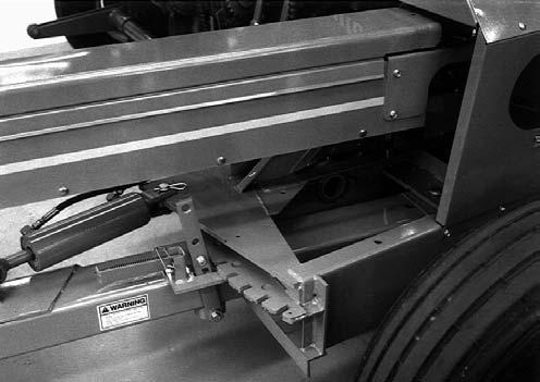
Downstop (Fig. 24)
The Downstop Adjustment can be used to limit how far down the Lift Arms will travel when a Row Crop Attachment is being used on the Harvester. Adjust the Downstop so that, with the Lift Cylinder retracted, the height to which the Attachment will be lowered is that level which will keep the skids off the ground and the rotary sickles out of the dirt and stones. To adjust the Downstop position:
1.Extend lift cylinder and remove Downstop Pin.
2.Lower the Attachment to the desired position.
3.Insert Downstop Pin into its highest hole possible.
4.Adjust the Downstop Stud against the Downstop Pin. If the Stud will NOT go down and touch the Square Pin, retract the Stud enough to allow moving the Square Pin upwards one hole. Then, adjust the Stud down against the Square Pin. The Downstop adjustment will vary with different Row Crop Attachments.
Lift Height (Fig. 25)
A Lift Height Adjustment Cam, located behind the Lift Cylinder Link, is used to control the height to which the Lift Arms will raise the Feeder Attachment. The Cam requires readjustment anytime the mounted Attachment raises too high and strikes the Harvester Feed Roll Housing.

To adjust the Cam, retract the Lift Cylinder and loosen the 3/4 Bolt which clamps the Cam between the Lift

Assembly Plates. Loosen the Bolt only enough to allow the Cam to be rotated. Turn the Cam to position its high side toward the Lift Link for the maximum upward travel of the Attachment or, turn the Cam to position its low side toward the Lift Link for the minimum upward travel of the Attachment. After the desired position is tested and obtained, retighten the Nut on the 3/4 Bolt to lock the Cam in the position selected.
Slowly raise the Attachment and recheck the Attachment clearance to the Feed Roll Housing. Also check for ample clearance between the Feed Roll Sidesheets and the Attachment. If the Attachment, when raised, is still found to be striking the Harvester, readjust the Cam to reduce the maximum height of Attachment travel.
Lift Spring (Fig. 26)
The Harvester Lift Spring is provided to counterbalance the weight of the Attachment to either lighten its pressure on the ground or to better enable it to raise up and over stones, ruts or obstacles in the field. Spring tension can be readjusted to match the flotation requirements of various Attachments, as required.
To adjust Lift Spring tension, first completely retract the Lift Cylinder and lower the Attachment to the ground to determine the required Spring length setting. Then, using two wrenches, hold the Spring Nut with one wrench and turn the Spring Bolt with the other wrench to obtain the desired tension.
NOTE: Raise the Attachment to reduce the spring load on the Spring Adjusting Bolt to make it easier to turn the Bolt. Then, lower the Attachment again to gauge the float effect of the Spring.
For a Hay Attachment, the Spring tension should be adjusted to counterbalance the Attachment. It should take approximately 50 lb (11.2 N) of lift at the Hay Hold-down Bar to raise the Attachment.
If a Water Tank option is being used on the Hay Attachment, adjust the Lift Spring to provide maximum tension. Maximum tension can be adjusted whenever a Row Crop Attachment is mounted, provided the Row Crop Attachment still lowers all the way to the Downstop without assistance. However, many users leave the Spring set in the hay attachment position.
Blower
Belt Idler (Fig. 27)
Belt tension is maintained by a Spring-loaded Belt Idler. Tension on the Belt is factory set and requires NO further readjustment unless the Belt slips and becomes hot. In this case, the Belt tension MUST be increased by stretching the Spring further. The Spring Tension Strap contains multiple holes to allow for Spring tension adjustment.

Drive Belt (Fig. 27)

The Drive Belt can be removed, for replacement, by raising the Idler above the Belt, pushing the slack Belt toward the Blower and, then lowering the Idler until the Spring is loose. Use an appropriate length of 1 (25 mm) diameter pipe, or equivalent, for additional leverage.
Fan Paddles (Fig. 28)
Over long periods of Harvester use, the tips of the four Blower Fan Paddles will wear and therefore require readjustment. The position of the Fan Paddles should be checked (and, if necessary, readjusted) after every 100 hours of operation.
Each Paddle Tip should be approximately 1/32 to 1/16 (0.8 to 1.6 mm) away from the Blower Rim Sheet at the 6 o’clock (bottom) position. An excellent method for checking the setting is to place a nickel and a dime side by side on the Rim Sheet. When the Paddle is rotated across the coins, it should pick up the nickel and leave the dime. To adjust the Paddles, proceed as follows:
1.Make sure the Rim Sheet is clean (free of grass, gum, or dirt). Clean the Rim Sheet by running wet forage through the Harvester or by scraping it, if you do NOT have an accessory Water Tank.
Warning
BE SURE to exercise the MANDATORY SAFETY SHUTDOWN PROCEDURE (page 8) BEFORE adjusting this unit.
2.Check the Rim Sheet Wear Liner for dents and holes; replace if necessary.
3.Check to see if the Blower Paddle Arms are bent; replace or straighten, as required.
4.Loosen the four 1/2 Hexagon Nuts on each Paddle only enough so that the Paddles can be tapped toward the Rim Sheet. Access to the Nuts can be gained through the Blower inlet opening in the rear Sidesheet. Align the Paddles over their full 4-3/4 (121 mm) width so that the Tips are 1/32 to 1/16 (0.8 to 1.6 mm) away from the Rim Sheet.
NOTE: If after several adjustments of the Paddles, they cannot be moved any closer to the Rim Sheet, replace them according to the procedure outlined under the Blower Fan Paddle topic in the Service chapter of this manual.
5.Check the screws and nuts which secure the Paddle Arm to the Blower Disc to see that they are properly secured.
6.After all Paddles are adjusted and the attaching hardware is tightly secured, rotate the Fan again (by hand) to insure that it turns freely; if NOT, check and remove the obstruction.
7.Replace the Rear Shields and Guards. Run the Harvester at idle speed and listen for noise from the Blower.
Increase the tractor RPM to full throttle and again listen for noise from the Blower. If any noise problem is heard, exercise the MANDATORY SAFETY SHUTDOWN PROCEDURE (page 8) and then proceed to identify and correct the problem.
Shear Bar (Figs. 29, 30 & 31)
NOTE: The two routine maintenance procedures that have the most significant effect on the quality of cut and on fuel efficiency are Knife sharpening and Shear Bar adjustment. Frequent sharpening of the Knife edge accompanied by the proper Shear Bar adjustment will significantly increase the life of the Knives and the Shear Bar, as well as reduce the amount of fuel required to chop the forage. In most cases, daily sharpening of the Knives and proper adjustment of the Shear Bar to the Knives will be sufficient. However, in areas where the soil is excessively sandy, more frequent Knife sharpening and Shear Bar adjustment may be necessary.
After sharpening the Cylinder Knives, the Shear Bar requires a slight amount of adjustment toward the Knives. All Shear Bar adjustments are performed on the right side of the Harvester with all Covers and Shields kept in place. With the Harvester Cylinder operating at tractor engine idle speed and the Shifter Transmission deactivated by turning the Keyswitch OFF and removing the Key, proceed to adjust the Shear Bar as follows: NOTE: It is NOT necessary to loosen the Holddown Bolt on the right end of the Shear Bar while adjustments are being made. Also, the Springloaded Hold-down Pin on the left side should NEVER be loosened, even when removing the Shear Bar.

Setting the Shear Bar requires listening for the Knives to tick the Shear Bar but, it is possible for the Knives to hit the right side of the Shear Bar when you are adjusting the left side and vice-versa, thus giving a wrong indication of the closeness of a Knife to the Shear Bar.
NOTE: DO NOT completely loosen the Nuts in steps 1 and 2. The adjustment will be more accurate if both Nuts ALWAYS press against the Shear Bar.
Run Knife Cylinder at low speed.
1.Bring right side to tick.
2.Back off right side to stop tick.
3.Bring left side to tick.
4.Back off left side to stop tick.
NOTE: When the cutting edge of the reversible Shear Bar NO longer stays sharp, the Shear Bar can be removed and reversed (end-for-end) to place a new sharp edge toward the Knives. After both edges are worn-down the Shear Bar MUST be removed and replaced with a new Shear Bar.
DEFLECTOR (Fig. 32)

The Harvester Deflector is equipped with Electric Controls. Horizontal Extensions and/or Vertical Extensions are available to respectively lengthen and/or raise the point of discharge from the Cap end of the Deflector. Approximate length and height variations for the Deflector with or without different accessory Extensions are shown.
Warning
Properly support the deflector whenever it is necessary to remove the attaching hardware between it and the blower outlet or a vertical extension. The deflector, outlet and extensions have matching flanges which are bolted together; when the hardware is removed, the components will separate and fall.
A - Deflector
B - Vertical Extension
C - Horizontal Extension
D - Wagon Hitch Pin to End of Cap
E - Height from Ground
F - Tongue Pin Hole to Wagon Hitch Pin Hole
[ 198–1/4 (5036 mm)]
All Dimensions are in Inches (Millimeters) Unless Otherwise Noted
NOTE: Actual Measurements vary based on Tire size and Wheel Spindle position.
Fig. 32
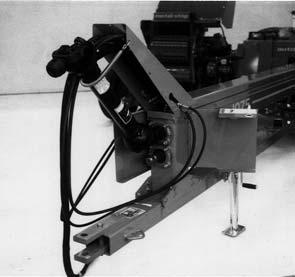
Tongue (See Fig. 26)
The Tongue of the Harvester can be remotely repositioned from the tractor seat after the Transport Lock
Mechanism has been locked-out as shown. When the Harvester is transported on the highway, the Lock Mechanism MUST be locked into the “Transport” position. This is accomplished by moving the Tongue into the “Transport” position, removing the Latch Lockpin and moving the Tongue until the Latch falls into the “Transport” Hole. BE SURE to reinstall the Lockpin to lock the Latch into the Hole.
Drive Chains
The various Drive Chains of the Harvester are provided with appropriate adjustable-position or self-tensioning mechanisms.
Length-of-Cut Drive Chain (Fig. 33)
Unlock the Chain Adjustment Knob on the Length-ofCut Frame and adjust the Chain tension with the Knob for a slack of 1/4 to 3/8 (6 to 9.5 mm) in the strand of Chain between the Torque Sensor Sprocket and Drive Sprocket. After proper Chain tension is adjusted, BE SURE to lock the Knob.
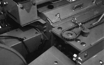
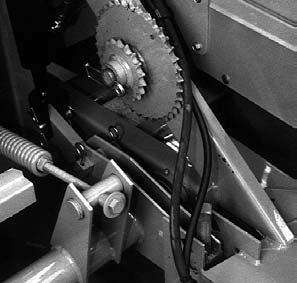
Attachment Driver (Fig. 34)

The Attachment Driver Chain has an Idler Sprocket on the slack side of the Chain. Tension on the Chain should be checked after every 10 hours of operation and readjusted (if necessary) for a slack of 1/4 to 3/8 (6 to 9.5 mm) in the strand of Chain between the Torque Sensor Sprocket and the Drive Sprocket.

IMPORTANT: When re-tightening the Idler Sprocket mounting bolt, make sure the Idler Sprocket lines-up with the Chain. Also, too much Chain tension can result in excessive Chain and Sprocket wear; avoid applying too much tension.
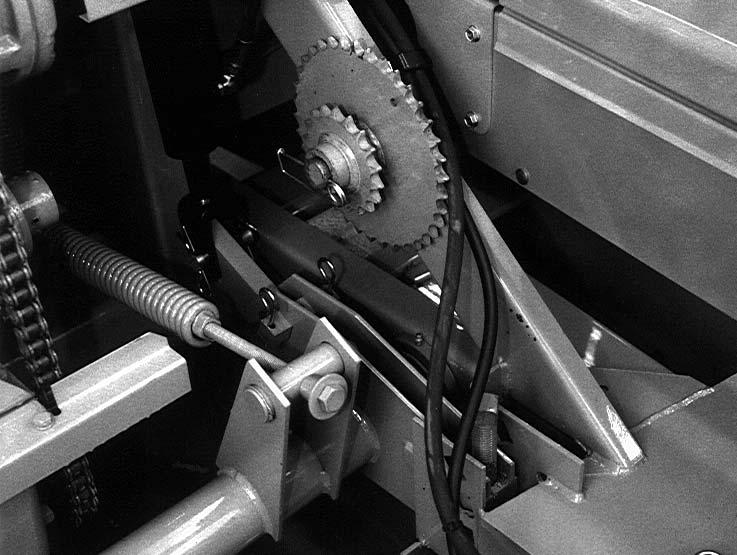
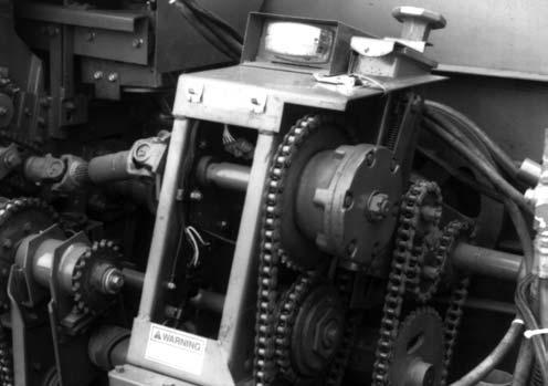
Lower Feed Rolls (Fig. 35)
The Lower Feed Roll Drive Chain tension is adjusted with a Chain Slide Mechanism. Chain deflection should be checked after every 50 hours of operation and readjusted (if necessary) for a 5/16 (8 mm) deflection on the strand of Chain opposite the Slide.
Shifter Transmission Drive (Fig. 33)
The Shifter Transmission Drive Chain has a self-adjusting Idler which requires NO further readjustment.

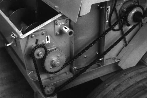
Auger Drive Chain (Fig. 36)
The Auger Drive Chain has an adjustable Idler on the slack side of the Chain. Tension on the Chain should be checked after every 10 hours of operation and readjusted (if necessary) for a slack measurement of 0.50 (2.5 mm) with pressure placed on the Chain between the Shear Device and Drive Sprocket.
Upper Feed Rolls (Fig. 37)
The Upper Feed Roll Drive Chain has self-adjusting Roller Slides to maintain proper operating Chain tension; NO further adjustment is required. If, after a time, Slide wear is detected, the attaching hardware can be temporarily loosened and the Slide rotated to a new position.
Tension on each Spring can be readjusted by tightening each Spring Tensioning Bolt until there is no looseness and then one additional revolution of the Bolt. Then, tighten the Nut against the Nut casting. Do NOT tighten the Nut against the Frame Flange because the Bolt must be free to tilt with the Spring.
CROP PROCESSOR ROLLER MILL (Optional)
Roll Spacing
The lower mill Roll is in a fixed position and the upper roll is adjustable to allow for changing the clearance and resultant coarseness or fineness of the processed material. Reposition the Adjustment Sprocket to change the position of the upper Roll. To move the upper Roll downward (reducing the clearance), remove the Chain Lock Pin and use the Wrench to turn the Adjustment Sprocket counterclockwise. To move the upper Roll upward, remove the Chain Lock Pin and use the Wrench to turn the Adjustment Sprocket clockwise. When adjusting, each revolution of the Wrench will move the Upper Roll 0.20 inch (5 mm). Moving the Chain one Link will move the Upper Roll 0.010 inch (0.25 mm). After the adjustment has been made, always lock your setting by inserting the Chain Lock Pin. Store the Wrench in the Tool Box.

Roll Alignment
If the Rolls ever become out of alignment, (more gap between Rolls on one end than on the other) they MUST be realigned to maintain feed consistency. This can be accomplished by first positioning the rolls at minimum clearance with the Adjustment Wrench and then removing the Chain from the control Sprockets by removing its connecting link. The Rolls can then be brought back into alignment by turning the Adjustment Sprocket. The space between the Rolls should be checked with a feeler gauge to establish an even gap. The minimum clearance is intended to be 0.020 inch (0.5 mm). When a satisfactory setting has been established, replace the Chain and Connecting Link.
Minimum Roll Spacing
FEED ROLL SPRINGS (See Fig. 35)
Tension Springs are provided on both sides of the Feed Roll Housing to apply pressure on the Feed Rolls while material is traveling between them. The Feed Roll Springs are factory adjusted so that all looseness (play) is eliminated. Tension needs only to be checked and adjusted if they are loose or after service has been performed which requires removing the Feed Roll Springs and Rolls.
The Rolls require clearance between them as they rotate at different speeds. Without clearance the Rolls will self destruct.
The minimum Roll clearance setting is preset at the factory and should NOT require additional readjustment. However, if the Rolls are disassembled or require adjustment to compensate for wear, use the following procedure.
First verify that the Rolls are parallel to each other and adjust if necessary (see instructions above).
Position the Rolls at their minimum clearance by turning the adjustment Sprocket counter clockwise until the stop bottoms out.
The clearance at this position should be 0.020 inch (0.5 mm). Use a feeler gauge to verify this. If adjustment is necessary, it can be adjusted by loosening the Jam Nut of the 3/4 inch Stop Bolt and turning the Bolt up or down as required to attain the 0.020 inch (0.5 mm) minimum Roll spacing. There is an adjustment for each end of the Upper Roll After adjustment is completed, MAKE SURE to re–lock the Jam Nuts to the adjusting Bolts. The Roll Tension Springs on the lower Roll are set at the factory to maintain the correct amount of pressure, and should NOT be readjusted. The correct spring length is 4.5 inch (114 mm). These Springs allow the Rolls to separate so foreign objects, such as stones, can pass between the Rolls. After the object passes, the Spring pressure will restore the Roll to its original position.
Belt Tensioner (Fig. 38)
The matched set of four Mill Drive Belts are tensioned with a Spring. The Mill Drive Belts should be checked for cracks, tears, evidence of oil and proper Spring tension every 50 hours and the adjustment checked every time the Roll spacing is changed. The Spring is properly tensioned when a gap of 7/8 inch (22 mm) is measured as shown. Adjustment is accomplished by retracting the Lock and rotating the Knob shown. NOTE: It is not necessary to remove the Drive Shield to measure the gap. This distance is visible with the Shield installed.
KNIVES (Fig. 39)
The Cutting Cylinder Knives will have to be readjusted whenever 1/4 (6 mm) or more is ground-off through repeated sharpening because the Shear Bar has only 1/4 (6 mm) of actual adjustment. To adjust the Knives, proceed as follows:
Warning
BE SURE to exercise the MANDATORY SAFETY SHUTDOWN PROCEDURE (page 8) BEFORE adjusting the knives.
1 – Adjustment Lock
2 – Adjustment Knob
3 – Adjustment Measured Here, 7/8 inch (22 mm)
Fig. 38: Drive Shield Removed for Clarity
1.Open the Sharpener Cover. Remove the Cylinder Covers. While it is not necessary, it is recommended to remove the Crop Processor or Transition. Crop Processor removal is covered in the Crop Processor Operator’s Manual.
2.Remove the rear Cylinder Side Sheet Tie Support.
3.After cleaning out the space between the Shear Bar and the Scraper, move the Shear Bar forward to the end of its travel.
4.Install the Knife Set-up Rod (which is stored under the Knife Sharpener Cover) through the access holes in the Cylinder Sidesheets as shown.
5.Loosen the (3) Knife Bolts just enough to permit the Knife to be tapped into position.
6.Adjust the Knife to just clear or just touch the Setup Rod along the entire length of the Knife.
7.Tighten all (3) Knife Bolts to 220/240 ft-lb (300-325 Nm) of torque and recheck clearances. Do not over-torque!
8.Repeat steps 4, 5 & 6 for all of the Knives. Remove and store the Knife Set–up Rod. Reinstall all removed components EXCEPT the Cylinder Cover Sharpener Access Insert. Sharpen the Knives and set the Shear Bar according to the instructions under those topics.
LENGTH-OF-CUT (See Fig. 33)
The Harvester Length-of-Cut is regulated by two factors: the number of Cylinder Knives and the Lengthof-Cut Sprocket which is mounted on the Shifter Transmission Output Shaft.

Refer to the Length-of-Cut chart provided for Sprocket and Knife combinations. Refer to the Service chapter for Knife removal and replacement details.
NOTE: Only 8 Knives (or 4 Knives equally spaced) should be used. Any other quantity or spacing of Knives is NOT recommended.
To change the Length-of-Cut Sprocket, proceed as follows:
1.Unlock the Chain Adjustment Knob on the Length-of-Cut Frame and completely release Chain tension.
2.Install the desired Length-of-Cut Sprocket using the existing Washers to align the new Sprocket.
3.After the desired Length-of-Cut Sprocket is installed, readjust the slack on the Length-of-Cut Drive Chain. To properly adjust the slack, rotate the Knob by hand until Chain is tight. Then, rotate the Knob counterclockwise 1/4 turn, to provide the correct slack. After the Chain slack is adjusted, BE SURE to reset the Knob Lock.
Length-of-Cut Chart in Inches (millimeters)
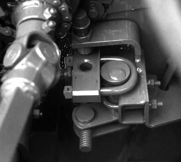
TORQUE SENSOR CONTACT POINTS (Fig. 40)
To operate with maximum capacity, the Contact Points for each Torque Sensor (one on the Feed Roll Drive and one on the Attachment Drive) MUST be maintained with a 0.036 to 0.060 (0.9 to 1.5 mm) gap between the Sensor Contact Point and the adjacent Sprocket. A lesser gap causes the Contact Point touch the Sprocket due to Sprocket wobble or under lighter loads. A greater gap causes the Torque Sensor device to ratchet without releasing the Electric Clutch.
NOTE: The Torque Sensor device has a very short ratchet life.
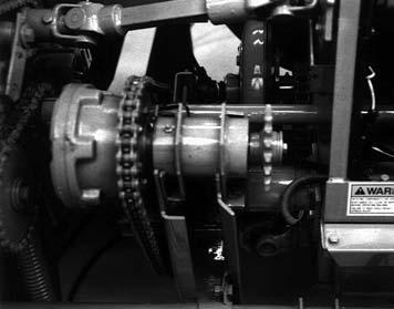
METAL STOP (OPTIONAL) SYSTEM SOLENOID & STOP PAWL (Fig. 41)
When the Solenoid is retracted (Normal Operating Position), the Stop Pawl is to be held 1/8″ (3 mm) away from the highest point on the Ratchet Wheel as shown. To adjust this distance, first loosen the (3) Bolts in the Solenoid Mount and slide the Mount towards or away from the Ratchet Wheel. After the 1/8″ (3 mm) clearance is obtained, tightly secure the (3) Bolts. The (3) Rings, between the Solenoid and the Stop Pawl, MUST NOT be twisted. The Ring in the Solenoid Eyebolt and the one in the Stop Pawl are to be horizontal (positioned sideways). The center Ring is to be vertical (perpendicular to the other two). Rotate the Eyebolt, inside the Solenoid Boot to untwist the Rings. After the preceding adjustments are made, recheck the Solenoid operation to insure that the Stop Pawl moves freely.
SCRAPER (See Fig. 31) WARNING
BE SURE to exercise the MANDATORY SAFETY SHUTDOWN PROCEDURE (page 8) BEFORE adjusting the scraper.
IMPORTANT: The Scraper MUST ALWAYS be set within 0.010 (0.25 mm) from the Smooth Feed Roll in order to prevent excessive wear on the Length-of-Cut Sprocket and to help prevent excessive horsepower consumption.
The Scraper, for the Smooth Lower Rear Feed Roll, can be adjusted or removed (if necessary) from outside the Harvester. The Scraper should be maintained in contact with the entire width of the Feed Roll. If readjustment is required, loosen the 1/2 Hexagon Nuts on each end of the Scraper and tap the Scraper ends down. If material is caught between the Scraper Tip and the Feed Roll, remove the Scraper by loosening the Nuts to permit the mounting bolts to drop-down in the slots in the Scraper and Shear Bar Support.
NOTE: Raise the Stem Guides, above each end of the Scraper, 1/4 (6 mm) to provide clearance for removing the Scraper.
Pull the Scraper out the right side and clean it. If the Scraper is badly worn or bent, replace it. Reinstall the Scraper by reversing the above procedure. Raise the 1/2 Bolts and Nuts, at each end of the Scraper, in the slots and tighten the Nuts so they are snug. Then, tap the ends of the Scraper down and secure it by tightening the Nuts.
IMPORTANT: When the Scraper is reset, BE SURE to set the Stem Guides down against the Shear Bar and 1/32 to 1/16 (0.8 to 1.6 mm) from the Knives at their lower end. Carefully rotate the Cutting Cylinder (by hand) to make sure the Knives do NOT strike the top of the Stem Guides. MAKE SURE that the Stem Guide Bolts are tight. Loose Bolts will allow the crop to push the Guides into the Knives and severely damage the Cutting Cylinder. Periodically check the area between the Scraper and Smooth Feed Roll to make sure that it is clean. This area can be cleaned from the outside of the Harvester by pushing a rod through the hole in the Sidesheet, between the Scraper and Feed Roll. It is build-up in this area that causes higher loads which wear the Sprockets and increase horsepower consumption.
STEM GUIDES (Fig. 31)
Right and Left Stem Guides are located above the Shear Bar at each end. These Guides prevent forage stems from moving around the ends of the Knives. The bottom edges should be set down against the Shear Bar and the curved rear edges should be positioned about 1/32 to 1/16 (0.8 to 1.6 mm) from the Knives.
To adjust the Guides, loosen the two 3/8 Hexagon Head Cap Screws which are threaded into the Guides. Move the guide by tapping the 3/8 Screws. When the Guides are properly positioned, retighten the two Screws.
IMPORTANT: MAKE SURE that the Stem Guide Bolts are tight. Loose Bolts will allow the crop to push the Guides into the Knives and severely damage the Cutting Cylinder.
TIRES, WHEELS & AXLES
The Forage Harvester can be obtained with either Single or Tandem Axle configuration.
Single Wheel Axles, Wheels & Spindles (Figs. 43 & 44)
The Axle Extensions can be placed into and secured to the Harvester Frame in any one of several positions to align the Wheels and Tires between crop rows. The various positions for the Axle Extensions are illustrated. A single 1/2 x 6 Bolt, Lock Washer and Hexagon Nut are used to secure the Extension to the Frame.
The Single Wheel Spindles can also be raised or lowered to adjust the height of the Harvester Frame to match the requirements of the Attachment and field conditions. The various positions for the Spindles are illustrated. Each Spindle is secured to the Axle Extension with (4 each) Carriage Bolts, Lock Washers and Nuts.
Warning
BE SURE to properly position the jack under the frame axle and make sure that the jack base is firmly supported so that the jack does not slip off the frame axles.
To move the Wheels and Tires in or out or to adjust the Spindle heights, block the Harvester and jack the Frame up. Remove the attaching hardware, adjust the Axle Extensions in or out and then re–secure the attaching hardware. To change the Spindle height, temporarily loosen (but do not remove) the four Carriage Bolts in each Spindle. Then, Slide the Spindle up or down and re–secure the Spindle attaching hardware. BE SURE to set both Spindles to the same height.
Tandem Wheel Axles, Spindles, Wheels & Tires (Fig. 44 & see Fig. 43)
The Tandem Axle Extensions can be placed into and secured to the Harvester Frame in any one of several positions to align the Wheels and Tires between the crop rows. The various positions of the Axle Extensions are illustrated. A single 1/2 x 6 Bolt, Lock Washer and Nut are used to secure each Extension to the Harvester Frame.
The Tandem Wheel Spindles can also be raised or lowered to adjust the height of the Harvester Frame to match the requirements of the Attachment and field conditions. Each Spindle is secured with a total of six 1/2 x 1-1/2 Cap Screws, Lock Washers and Plain Washers. The various positions for the Spindles are illustrated. BE SURE to adjust all four Spindles to the same height.
NOTE: The top–most Spindle Mounting Bolts require only to be temporarily loosened when the Spindle positions are readjusted.
To move the Wheels and Tires in or out or to adjust the Spindle positions, block the Harvester and jack the Frame up. Remove the attaching hardware, readjust the Axle Extensions or Spindles and re–secure the hardware.
Warning
BE SURE to properly position the jack under the frame axle and make sure that the jack base is firmly supported so that the jack does not slip off the frame axles.
NOTE: The following information applies only to operating a Harvester equipped with Tandem Axles in fields rutted by the wheels of center pivot irrigators.
Two metal doughnut-shaped Spacers (076279) are provided with the Tandem Axle assemblies. These Spacers can be assembled onto the short shafts which protrude between the fork of each Axle Extension and secured with the Cotter Pins provided. When installed, the Spacers greatly limit the Wheel Beam oscillation. They are recommended for use where center pivot irrigation systems are employed. Do NOT use the Spacers in any other conditions.
NOTE: The following information applies only to equipping Tandem Axles with other than the Tires furnished with each factory provided assembly.
A Tire, with larger than a 31 (790 mm) outside diameter, CANNOT be used on the right front Wheel if the Harvester is going to be operated with an HA1100 or HA1110 Hay Attachment. A larger Tire will interfere with the HA1100 or HA1110 Attachment Flotation Wheel and the right sidesheet of the Attachment will cut the Tire while passing over an object, which raises the right front Tandem Wheel as the Attachment drops below the normal ground position.
WAGON HITCHPLATE (Fig. 45)
The Wagon Hitchplate can be placed in any one of many positions to align the wagon tires between crop rows.
A -Tandem Axle Tires
B -Single Axle Tires
C -Wagon Hitch Plate
D -46 (1168) to 68-1/2 (1740)
E
F
G -Centerline of Cutting Cylinder
H -28 (711 to 51 (1300) Single (11L x 14)
All Dimensions are in Inches (Millimeters) Unless Otherwise Noted
A - Single Axle Extension (Top Surface)
B - Axle Extension
C - Spindle Plate
D - Wheel
E - High Harvester Spindle Position
F - Low Harvester Spindle Position
G - Spindle Bolt (1 of 4)
A - Left Side
B - Main Frame
C - Right Side
D - Transport Hitch Hole
E - Wagon Hitch Plate
Chapter 8 Lubrication
General Information Warning
NEVER lubricate this unit when any part of the machine is in motion. ALWAYS BE SURE to exercise the MANDATORY SAFETY SHUTDOWN PROCEDURE (page 8) BEFORE lubricating this equipment.


It is important to apply sufficient oil and grease to prevent excessive part wear and early failure.
IMPORTANT: Whenever service is performed on hydraulic components (valves, cylinders, hoses, etc.) or Transmissions, care must be taken to prevent discharging fluid onto the ground. Catch and dispose of fluid per local waste disposal regulations.
TRANSMISSION LUBRICATION (Figs. 46 & 47)
The lubricant level in both the Bevel Gearbox and Shifter Transmission should be checked after every 200 hours of operation and replenished, when necessary.
The Bevel Gearbox requires 7 U.S. Pints (3.3 liters) of SAE #140 EP Gear Lube. The Shifter Transmission has two oil reservoirs. The front reservoir requires 7 U.S. Pints (3.3 liters) of SAE 10W40 motor oil and is filled through the Breather Plug hole in the front of the Reverse Delay Switch, as shown.
The rear Reservoir requires 1 U.S. Pint (0.5 liter) of SAE 10W40 motor oil and is filled by removing the Plate on which the rear Reservoir Breather is mounted.
1 – Rear Reservoir Breather Plug and Plate
NOTE: Do NOT overfill either assembly; only fill them to the bottom of their Level Plug holes.
Drive Chains
Lubricate all Drive Chains every six to eight hours of operation using a good grade of foaming aerosol lubricant such as NAPA Chain and Cable Lubricant. This type of lubricant increases the life of the Chain three to four times over those lubricated at eight hour intervals with new or used motor oil. The recommended method is to spray the entire length of Chain on the center of the Rollers. It is more effective to oil Chains after use, while they are still warm.
IMPORTANT: To minimize wear on the Sprockets, the Chains should be replaced after they become worn and are 3% longer than their original length, or when the Tightener (where provided) has reached the end of its adjustment.
Ammonia Silage Additive
IMPORTANT: Gehl Company recommends against running ammonia silage additives through any part of the Harvester because of their damaging effects on Bearings.
If an ammonia silage additive must be added to the silage in the field, certain precautions MUST be taken. It should only be introduced at the Blower in the top portion of the Blower Outlet, in order to keep the ammonia away from the Bearings. The ammonia will cause the oil-carrying substance of the grease to dissolve in the Bearings, causing them to fail. Special grease MUST be used which can withstand the ammonia vapor effects. Two greases which stand up fairly well in the presence of ammonia are Aero Shell #7 (by Shell Oil Co.) and Chevron SRI (by Chevron Oil Co.). But, even these two greases will have to be replenished twice a day in those Bearings which are exposed to ammonia vapor.
Oiling
Apply motor oil on all of the points listed at the intervals specified.
Lubricate Every 10 Hours (or Daily)
The Rotating Telescoping PTO Drive Guard
Lubricate Every 50 Hours
Torque Sensor Contact Pivot Points
Auger Drive Shear Bolt Flange
Blower Belt Idler Pivot Points
Rear Feed Roll Guides (both sides)
Lubricate Every 100 Hours (or Annually)
Tongue Pivot Pin
All Hinged-Cover Hinges
Feed Roll Spring Strap Pivots (both sides)
Feed Roll Stabilizer Pivots (both sides)
Deflector Control Worm Bearings
Crop Processor Roll Adjustment Screws and Guides
Crop Processor Drive Belt Tension Adjustment Screw
Hydraulic Circuits
The Harvester is equipped with two hydraulically powered control systems; the Attachment Lift Cylinder system and the optional Tongue Control system. BE SURE to check and maintain the tractor hydraulic fluid level in accordance with the total circuit requirements of your particular Harvester.
Greasing
IMPORTANT: Grease all fittings at intervals of operation listed, after pressure washing, before and after storing unit, and as listed. Use a good grade of lithium-base grease.
Wipe dirt from the fittings before greasing to prevent dirt from being forced into the Bearing or pivot. Replace any missing fittings when noticed. Force grease into the fitting until it comes out at the Bearing Seal or the Shaft. To minimize dirt build-up, avoid excessive greasing.
IMPORTANT: In addition to the fittings, repack the Wheel Bearings at least once a year. Apply a coat of grease, at least twice each season to Front Feed Roll Guides (both sides) and to the Deflector Worm and Gear. Periodically lubricate the Telescoping Drive Shaft and Tube.
Grease Fitting Locations
Grease Every 10 Hours (or Daily)
1.Telescoping Drive (3 places)
2.Main Drive Reversing Transmission (3 places)
3.Main Drive Cross
4.Right Feed Roll Stabilizer Bar Bearing
5.Left Feed Roll Stabilizer Bar Bearing
6.Right Feed Roll Guide Bearing
7.Left Feed Roll Guide Bearing
8.Upper Feed Roll Drive (3 places)
9.Lift Tube Cast Bearing
10.Cylinder Drive Crosses (2 places)
11.Right Lift Tube Sleeve Bearing
12.Left Lift Tube Sleeve Bearing
13.Main Drive Shear Device (2 places)


14.Electric Clutch Hub
15.Attachment Drive Cross
16.Remote Right Cylinder Bearing Housing


17.Left Cylinder Bearing Housing
18.Front Blower Bearing
19.Rear Blower Bearing
20.Crop Processor Upper Roll Bearings (2 Places)
21.Crop Processor Lower Roll Bearings (2 Places)
Rear Master
Grease Every 50 Hours
22.Blower Outlet Flange (4 places)
23.Right Lower Rear Feed Roll Bearing
24.Right Lower Front Feed Roll Bearing
25.Right Upper Front Feed Roll Bearing
26.Right Upper Rear Feed Roll Bearing
27.Remote Left Upper Front Feed Roll Bearing
28.Remote Left Upper Rear Feed Roll Bearing
29.Remote Left Lower Rear Feed Roll Bearing
30.Remote Left Lower Front Feed Roll Bearing
31.Feed Roll Input Chain Idler Arm Pivot
32.Auger End Bearings (2 Places)
Grease Every 100 Hours (or Annually)
33.Knife Sharpener Adjustment Screw
34.Left Quick-switch Attachment Drive Hub

35.Processor Belt Idler Arm Pivot

36.Left Shear Bar Adjustment Cam

37.Feed Roll Shear Flange(s) (1 place Torque Sensor units, 2 places Shear Bolt-equipped models)

Grease Each Time an Attachment is Changed or At Lease Once a Year
38.Left Lift Roller
39.Right Lift Roller

The Grease Fitting list is repeated for your convenience.
Grease Every 10 Hours (or Daily)
1.Telescoping Drive (3 places)
2.Main Drive Reversing Transmission (3 places)
3.Main Drive Cross
4.Right Feed Roll Stabilizer Bar Bearing
5.Left Feed Roll Stabilizer Bar Bearing
6.Right Feed Roll Guide Bearing
7.Left Feed Roll Guide Bearing
8.Upper Feed Roll Drive (3 places)
9.Lift Tube Cast Bearing
10.Cylinder Drive Crosses (2 places)
11.Right Lift Tube Sleeve Bearing
12.Left Lift Tube Sleeve Bearing
13.Main Drive Shear Device (2 places)
14.Electric Clutch Hub
15.Attachment Drive Cross
16.Remote Right Cylinder Bearing Housing
17.Left Cylinder Bearing Housing
18.Front Blower Bearing
19.Rear Blower Bearing
20.Crop Processor Upper Roll Bearings (2 Places)
21.Crop Processor Lower Roll Bearings (2 Places)
Grease Every 50 Hours
22.Blower Outlet Flange (4 places)
23.Right Lower Rear Feed Roll Bearing
24.Right Lower Front Feed Roll Bearing
25.Right Upper Front Feed Roll Bearing
26.Right Upper Rear Feed Roll Bearing
27.Remote Left Upper Front Feed Roll Bearing
28.Remote Left Upper Rear Feed Roll Bearing
29.Remote Left Lower Rear Feed Roll Bearing
30.Remote Left Lower Front Feed Roll Bearing
31.Feed Roll Input Chain Idler Arm
32.Auger End Bearings (2 Places)
Grease Every 100 Hours (or Annually)
33.Knife Sharpener Adjustment Screw
34.Left Quick-switch Attachment Drive Hub
35.Processor Belt Idler Arm Pivot
36.Left Shear Bar Adjustment Cam
37.Feed Roll Shear Flange(s) (1 place Torque Sensor units, 2 places Shear Bolt-equipped models)
Grease Each Time an Attachment is Changed or At Lease Once a Year
38.Left Lift Roller
39.Right Lift Roller