7 minute read
CHAPTER 10 PREPARING FOR FIELD OPERATION

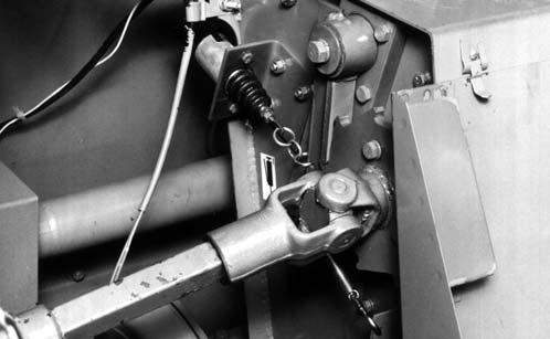
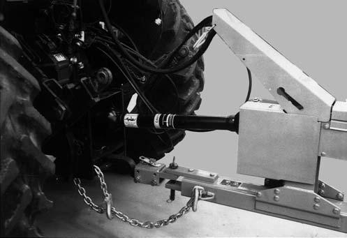
The Harvester, having a 1000 RPM 1-3/8″ PTO shaft or 1-3/4″ PTO shaft configuration, utilizes an equal angle drive length of 21.5″ (546 mm). This horizontal dimension is measured from the locking ring groove on the tractor PTO to the center of the drawbar pin hole. To operate the 1-3/8″ drive, your tractor must have an extendable drawbar. If your tractor does not have this feature, a 4″ (102 mm) Quick Attach Drawbar Extension is available.
the Harvester Tongue with the tractor drawbar and reduce the amount of side to side movement. The tractor drawbar height should be adjusted to position the PTO as parallel as possible to the drawbar. Keeping the drawbar in-line and minimizing side to side movement is essential in eliminating drive-line vibration, especially when maneuvering corners.
On tractors that are unable to adjust the drawbar to the proper dimension, a 4 inch (102 mm) Quick Attach Drawbar Extension is available. Refer to Figure 73 for proper positioning.
The front to rear position of the tractor drawbar hitch hole centerline MUST be correct to insure the proper Universal Joint relationship. The tractor drawbar hole should be 21″ (533 mm) from the locking ring of the tractor PTO Shaft, or 17″ (432 mm) from the locking ring of the tractor PTO Shaft when using the 4 inch (102 mm) Quick Attach Drawbar Extension.
1 – Tractor Drawbar*
2 – 1000 RPM Tractor 1-3/8″ or 1-3/4″ PTO Shaft*
3 – 21.5″ (546 mm), This is measured from the Retaining Groove in the Tractor PTO Shaft to the center of the Tractor Drawbar Hitch Pin hole.
4 – 21.5″ (546 mm), This is measured from the Retaining Groove in the Harvester Main Drive Shaft to center of the Tractor Drawbar Hitch Pin hole.
5 – 7.9 to 13.8″(150 to 300 mm)*
6 – 13 to 22″ (330 to 560 mm)* (Top of Drawbar to Ground)
7 – Locking Hitch Pin [1 inch (25 mm) diameter]
8 – Tractor Drawbar Hitch Pin Hole Alignment Decal on PTO
* Tractor MUST comply with ASAE Standard S203 Fig. 72: 1-3/8″ or 1-3/4″ PTO 1000 RPM
TRACTOR HITCH ALIGNMENT (Figs. 72 & 73)
Position the tractor drawbar hitch hole centerline directly in-line with the tractor PTO Drive Shaft, and secure so as to eliminate any side to side movement of the tractor drawbar. If the tractor drawbar can NOT be positioned in-line, position it toward the left, as close as possible to the centerline of the PTO shaft. It is important to use a 1″ (25 mm) diameter Hitchpin (customer furnished) with the Harvester to help center
1 – Tractor Drawbar*
2 – 1000 RPM Tractor 1-3/8″ or 1-3/4″ PTO Shaft*
3 – 21.5″ (546 mm), This is measured from the Retaining Groove in the Tractor PTO Shaft to the center of the Tractor Drawbar Hitch Pin hole.
4 – 21.5″ (546 mm), This is measured from the Retaining Groove in the Harvester Main Drive Shaft to center of the Tractor Drawbar Hitch Pin hole.
5 – 7.9 to 13.8″(150 to 300 mm)*
6 – 13 to 22″ (330 to 560 mm)* (Top of Drawbar to Ground)
7 – Locking Hitch Pin [1 inch (25 mm) diameter]
8 – Tractor Drawbar Hitch Pin Hole Alignment Decal on PTO
9 – 4″ (102 mm) Quick Attach Hitch Extension
* Tractor MUST comply with ASAE Standard S203
Fig. 73: 1-3/8″ or 1-3/4″ PTO 1000 RPM with
4″ (102 mm) Quick Attach Hitch Extension
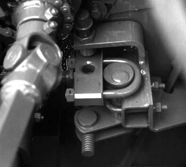
IMPORTANT: If this unit is connected to a tractor equipped with a clevis style drawbar, the clevis parts shown in dashed lines MUST be removed to prevent damage to the unit Driveline. See Fig. 74 for details.
4″ (102 mm) Quick Attach Drawbar Extension (Fig. 75) (Optional)
NOTE: The following information applies only to a Harvester which is going to be equipped with an optional 4″ (102 mm) Quick Attach Drawbar Extension
Install the Drawbar Extension following the instructions given in Figure 75.
Preparing Harvester
The following points of preparation will have to be made on the Harvester with respect to the Attachment being mounted. Refer to the Adjustments chapter of this manual and, if necessary, the appropriate Attachment Operator’s Manual for specific adjustment details and requirements.
1.Move the Harvester Axles in or out and relocate the Wheel Spindles to match the row spacing and height required for the particular Attachment.
2.Adjust the Attachment Float Spring on the Harvester.
3.Make appropriate Harvester Lift Height and Down-stop Adjustments. Refer to Attachment Positioning topic in the Adjustments chapter.
4.Adjust the Wagon Hitchplate position, if required.
HARVESTER-ATTACHMENT ALIGNMENT (Figs. 76 & 77)
Before proceeding to mount the Attachment, make sure that it is standing on level ground. Also check that the Quick-switch Yokes of the Attachment align vertically with the Quick-switch Pivots on the Harvester. Adjust the Attachment Stands to obtain the right height. NOTE: To better enable one man to mount the Attachment, it MUST be squared up, properly leveled and at the correct height. In addition, the Harvester approach into the Attachment MUST be squarely and directly head-on. BE SURE also to adjust the Attachment Throatsheets to match the Harvester Sidesheet opening.
1.Position the Harvester Lift Arms down to their lowest possible position by inserting the Down Stop Pin (1” Square Bar) into the hole in front of the Cylinder Link and then retracting the Lift Cylinder completely. This prevents the Lift Rollers from interfering with the Attachment while it is being mounted.
2.Drive the Harvester into the Attachment and observe that the Attachment Yokes slide over the Harvester Quick–switch Pivots and that the Attachment Throat Sheets slide between the Harvester Feed Roll Sidesheets.
3.Connect the Attachment to the Harvester by first using a punch/prybar inserted into the Quick–switch Pin mounting holes to clear them. Then, insert the Quick–switch Pins (from the Tool box) into the holes and secure them with the Hairpin Cotter Pins.
4.Slowly extend the hydraulic Lift Cylinder and remove the Down Stop Pin from in front of the Lift Cylinder Link.
5.Make the appropriate Attachment positioning adjustments according to the details provided in the Adjustments chapter of this manual.
Warning
Exercise the MANDATORY SAFETY SHUTDOWN PROCEDURE (page 8) before servicing this unit.
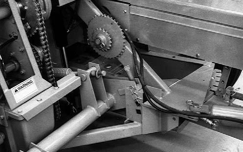
After proper alignment is obtained, secure the Drive Sprocket with the Cap Screw, Lock washer and Special Washer.
IMPORTANT: Tighten the Sprockets. Operating the Harvester with loosely secured Sprockets can cause excessive Shaft Spline wear.
7.Wrap the Attachment Drive Chain around the Drive and Driven Sprockets. Adjust the Chain length by adding or removing Links, as required. Refer to the Drive Chain Length Table for the necessary Chain length to match the Attachment being mounted.

Chapter 11 Transporting
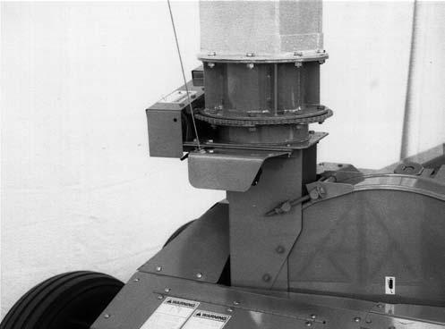
TONGUE (Fig. 78)
The Harvester is provided with a locking Tongue Latch Mechanism which MUST be securely locked for transporting the Harvester on a public highway. After the Tongue is relocated in the “transport’’ position, BE SURE the Lock Bar is engaged in its appropriate slot and secure it with the Lock Clip.
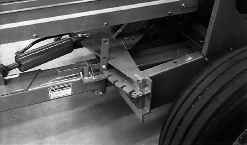
LIFT SYSTEM LOCK (Fig. 79) WARNING
The attachment lift system should be locked up whenever it is necessary to work under a mounted attachment
The hydraulically operated Lift System can be lockedup in order to maintain the Attachment in the “raised” position during transporting. To place the Lift System into the “Locked-up” position, first fully extend the Lift Cylinder and completely raise the Attachment. Exercise he MANDATORY SAFETY SHUTDOWN PROCEDURE (page 8) and install the Down Stop Pin into the “highest” possible (1 of 3) holes in the Lift Mechanism. BE SURE to lock the Pin in this position with the Cotter Pins provided. Then, turn the Down-Stop Bolt fully downward into contact with the Down Stop Pin.
SAFETY CHAIN & TRANSPORT LIGHTING (Fig. 80)
As required or when desired, the Harvester can be equipped with a safety chain for operation on public highways. Refer to the Optional Features & Accessories chapter for ordering information. The safety chain should be attached to the tractor and Harvester as shown. When attached in this manner, the safety chain should have the following characteristics:
1.Chain is sufficiently slack to allow turns and movements of either the tractor or the implement, without placing tension on chain.
2.Chain is of sufficient strength to hold the decoupled implement (and its load) and tow it to the shoulder.
Caution
ALWAYS follow state and local regulations regarding use of a safety chain and transport lighting when towing farm equipment on public highways. ONLY a safety chain (NOT an elastic or nylon/plastic tow strap) should be used to retain the connection between the towing and towed equipment, in the event of separation of the primary attaching system. BE SURE to check with local law enforcement agencies for your own particular regulations. Unless otherwise prohibited, use a Slow Moving Vehicle (SMV) emblem.
The Harvester is equipped with a Bracket for mounting a Slow Moving Vehicle emblem (SMV) on the rear of the Blower Housing. The SMV sign is customer supplied. Red, Amber and Orange Reflector Strips are also provided on the rear corners or the Harvester. Because of the variations in the Safety Laws for different states and localities, it may be necessary to change the Emblem Bracket mounting location. Your GEHL dealer can assist you in relocating the Bracket, if necessary.

A Transport Lighting Kit is available for use on public highways. Installation instructions are included in the Kit. Refer to the Optional Features & Accessories chapter of this manual for ordering information.
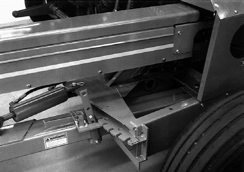
TOWING ON HIGHWAY (Fig. 81)
Warning
Good safety practice dictates that you NEVER tow an implement (without brakes) unless the towing vehicle weighs at least one-and-one half (1-1/2) times the weight of the towed implement and its load. For any public highway travel and to be in compliance with this rule, BE SURE that your tractor is heavy enough to counterbalance the weight of the Harvester and loaded wagon.
An additional Transport Hitch Plate, at the right end of the Hitch Channel, is also provided for long distance transporting. This Hitch Plate will position the Wagon all the way to the right, locating it more directly behind the Harvester, to reduce the overall width and making it easier for the tractor operator to view rearward.