20 minute read
CHAPTER 4 SAFETY


The above Safety Alert Symbol means ATTENTION! BECOME ALERT! YOUR SAFETY IS INVOLVED! It stresses an attitude of ‘‘Heads Up for Safety’’ and can be found throughout this Operator’s Manual and on the machine itself.
BEFORE YOU ATTEMPT TO OPERATE THIS EQUIPMENT, READ AND STUDY THE FOLLOWING SAFETY INFORMATION. IN ADDITION, MAKE SURE THAT EVERY INDIVIDUAL WHO OPERATES OR WORKS WITH THIS EQUIPMENT, WHETHER FAMILY MEMBER OR EMPLOYEE, IS FAMILIAR WITH THESE SAFETY PRECAUTIONS.
Our Company ALWAYS takes the operator and his/her safety into consideration when designing its machinery and guards exposed moving parts for his/her protection. However, some areas CANNOT be guarded or shielded in order to assure proper operation. Further, this Operator’s Manual and Decals on the machine warn of additional hazards and should be read and observed closely.
Danger
‘‘DANGER’’ indicates an imminently hazardous situation which, if not avoided, will result in death or serious injury.
Warning
‘‘WARNING’’ indicates a potentially hazardous situation which, if not avoided, could result in death or serious injury.
Caution
‘‘CAUTION’’ indicates a potentially hazardous situation which, if not avoided, may result in minor or moderate injury. May also alert against unsafe practices.
Mandatory Safety Shutdown Procedure
BEFORE unclogging, cleaning, adjusting, lubricating or servicing the unit:
1.Disengage the tractor PTO.
2.Shut off the tractor engine, place transmission in park and/or apply parking brake to prevent any tractor movement.
3.Remove the ignition switch key and take it with you when leaving the tractor seat.
4.Wait for all movement to stop and remove the Telescoping PTO Drive and ALL power connections from the tractor
5.Turn the Control Box Keyswitch Lock to “OFF,” remove the Key and take it with you.
ONLY when you have taken these precautions can you be sure it is safe to proceed. Failure to follow the above procedure could lead to death or serious bodily injury.
Additional Safety Reminders
Forage Harvesters are designed and intended to ONLY be used with a mounted Gehl Company attachment. The Gehl Company will NOT be responsible for operator safety if the Harvester is used without a properly mounted Gehl attachment.
Some photographs used in this manual may show doors, guards and shields open or removed for illustration purposes ONLY. BE SURE that all doors, guards and shields are in their proper operating positions BEFORE starting the tractor engine to operate the unit.
To ensure continued safe operation, replace damaged or worn-out parts with genuine Gehl service parts, BEFORE attempting to operate this equipment.
BE SURE to review and comply with ALL safety recommendations set forth in the tractor operator’s manuals.
This Harvester is NOT intended to be used as a stationary unit.
ALWAYS wear safety glasses with side shields while operating the Knife Sharpener. In addition, ALWAYS wear safety glasses with side shields whenever striking metal against metal. It is further recommended that a softer (chip–resistant) material be used to cushion the blow. Failure to heed could lead to serious injury to the eyes or other parts of the body.
Good safety practice dictates that you NEVER tow an implement (without brakes) unless the towing vehicle weighs at least one-and-one half (1-1/2) times the weight of the towed implement and its load. For any public highway travel and to be in compliance with this rule, BE SURE that your tractor is heavy enough to counterbalance the weight of the Harvester and wagon.
NEVER use your hands to search for hydraulic fluid leaks, use a piece of paper or cardboard. Escaping fluid under pressure can be invisible and can penetrate the skin and cause a serious injury. If any fluid is injected into your skin, see a doctor at once. Injected fluid MUST be surgically removed by a doctor familiar with this type of injury or gangrene may result.
ALWAYS follow state and local regulations regarding use of a safety chain and auxiliary lighting when towing farm equipment on public highways. Restrict highway towing speeds to 20 mph (32 km/h) maximum. BE SURE to check with local law enforcement agencies for your own particular regulations. Unless otherwise prohibited, use a Slow Moving Vehicle (SMV) emblem.
Only a safety chain (NOT an elastic or nylon/plastic tow strap) should be used to retain the connection between the towing and towed machines, in the event of separation of the primary attaching system.
Our Company does NOT sell replacement tires. In addition, tire mounting, service or inflation can be dangerous. Whenever possible, trained personnel should be called to service and/or mount tires, following the tire manufacturer’s instructions. If you do not have such instructions, contact your tire dealer or our Company. In any event, to avoid possible fatal or serious injury, follow the specific directives given in the Service chapter of this manual.
REMEMBER, it is the owner’s responsibility for communicating information on the safe use and proper maintenance of this machine.
The Harvester may have a factory-installed Metal Stop system that will automatically sense the presence of ferrous metal in the Feed Roll area. A metal detection activates a De–clutch Mechanism which stops the Feed Roll Drive, preventing metal from entering the Cutting Cylinder. When metal is detected, the Feed Rolls and attachment will stop and the Horn will sound inside the Control Box. To turn off the Horn, safely locate and remove the metal, reset the detection system, and perform the following steps in the sequence given:
Signaling Device Shut-off, Metal Location and Removal, and System Resetting Procedure
1.Move the Feed Roll Switch to “Neutral.”
2.Back the Harvester up 15 to 20 feet (5–7 m) so that there is NO crop under the attachment.
3.Reverse the crop out of the Feed Roll area and return the Feed Roll Switch to “Neutral.”
4.Disengage the tractor PTO, shut the tractor engine “Off”and remove the ignition key and take it with you when leaving the tractor seat.
5.Turn the Control Box Keyswitch to “Off”, remove the Key and take it with you.
6.Wait for ALL parts to stop moving.
7.Leave the tractor seat to remove the metal from the crop.
To safely locate the metal after it has been detected, and to remove it from the crop, it is recommended that the Harvester be backed away from the windrow or crop row a sufficient distance so that the portion of the crop containing the metal can be located and picked out, or that the small amount of crop can be set on the side for disposal later.
NEVER attempt to hand-feed the crop into the Harvester because the crop will feed faster than you can react to let go.

CHAPTER 5 CONTROLS & SAFETY EQUIPMENT
This Harvester is provided with several features for operator safety and convenience.
Caution
Become familiar with and know how to use ALL safety devices and controls on the Harvester (and tractor) BEFORE operating this equipment. Know how to stop Harvester operation BEFORE starting it. This Gehl Harvester is designed and intended to be used ONLY with a mounted Gehl Company attachment. The Gehl Company will NOT be responsible for operator safety if used without a completing attachment.
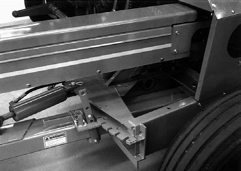
ATTACHMENT POSITIONING & LIFT SYSTEM LOCK (Fig. 1)
To place the Lift System into the ”Locked-up” position, first fully extend the Lift Cylinder and completely raise the Attachment. Exercise the MANDATORY SAFETY SHUTDOWN PROCEDURE (page 8) and install the Down Stop Pin into the highest possible hole in the Lift Mechanism. BE SURE to lock the Pin in this position with the Cotter Pins provided. Then, turn the DownStop Bolt fully downward into contact with the Down Stop Pin.
CAP CONTROL (Fig. 2)
The Deflector Cap is spring-returned to the raised (up) position. Lowering the Cap (to distribute the forage from the back to the front of the forage box) is accomplished by activating the appropriate tractor-mounted Control Box Switch which operates the Cap Control Gearmotor.
Mounted Attachment positioning is accomplished by the standard double-acting hydraulic cylinder which is provided. A Down Stop Bolt permits adjustment of the attachment’s lowest operating position. The Down Stop Pin in its highest position places the attachment in the transport position.
DEFLECTOR CONTROL (Fig. 2)
The Deflector can be rotated (to distribute the forage across the width of the forage box) by activating the appropriate tractor-mounted Control Box Switch which operates the Deflector Control Box Gearmotor.
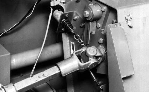
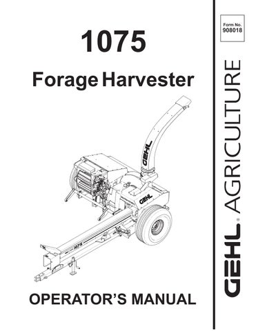
TONGUE POSITIONING (Fig. 3)
The Harvester Tongue can be repositioned manually by operating the Latch Mechanism which is linked by a Control Cord routed to the operator on the tractor seat. The Tongue can be remotely positioned by obtaining and installing a Hydraulically-operated Tongue Kit. When this Kit is installed and for field operation, the Transport Latch mechanism should be locked in the deactivated position. When transporting the Harvester, the Latch must be engaged and locked into position. A Tongue with the optional Kit is shown.


Warning
When transporting the Harvester, the latch mechanism MUST be locked in the “transport” position.
provided to warn of potential dangers as well as to display special operating procedures.
Warning
Read ALL warnings on the unit BEFORE operating it. DO NOT operate this equipment unless ALL factory–installed guards and shields are properly secured in place.
Implement Drive Line Guards (Fig. 4)
The Telescoping PTO Drive connection to the tractor is equipped with rotating Shields.
Warning
BE SURE that the rotating shields on the telescoping drive turn freely BEFORE starting the tractor engine.
GUARDS & SHIELDS
Wherever possible and without affecting machine operation, Guards, Shields and/or hinged Covers have been used on this equipment to protect potentially hazardous areas. In many places, Decals are also
A Guard is provided over the entire fixed-length portion of the Implement Drive Line, from the Front Bearing Support back to the Bevel Gearbox Input Shaft.
Miscellaneous Guards (Figs. 4 & 5)
Various latched and hinged Guards and Covers are provided on the Harvester to protect access points for service and/or adjustment.
Warning
BEFORE performing any work on the Harvester and BEFORE removing or opening any guards or covers, BE SURE to exercise the MANDATORY SAFETY SHUTDOWN PROCEDURE (page 8). BE SURE to replace ALL guards and covers BEFORE resuming operation.
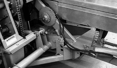
HITCHJACK (Fig. 6)
A Hitchjack (Jack) is furnished with the Harvester to support the machine when the tractor is disconnected as well as to facilitate aligning the Harvester Hitch with the tractor drawbar during hookup.

1 – Spring–loaded Locking Coupler
2 – Telescoping PTO Rotating Shields
3 – Hitchpin Positioning Decal on PTO
4 – Hitchjack in “Supporting” Position
Warning
BE SURE the lockpin is properly seated through the holes in the jack tube and the jack mount hub of the Harvester, BEFORE the disconnecting the Harvester from the tractor.
When the Jack is NOT being used to support the Tongue, remove the Lockpin and swing the Jack into its “storage” position. Wrap the Lockpin Chain around the Jack Handle (to hold it up) and then insert the Lockpin through Jack Tube and Tongue Hub to secure it.
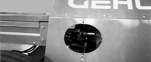
KNIFE SHARPENER (Fig. 7)
The Harvester is equipped with a factory-installed Knife Sharpener for sharpening the Cylinder Knives. The Sharpener is operated when the Cutting Cylinder is rotated in a reverse direction. A reversing PTO connection is provided on the front of the Hitch Pole.


OVERLOAD PROTECTION (Figs. 8, 9, 10 & 11)
All Harvesters are provided with a shear device on the Main Input Drive Shaft and on the Auger Drive. On Metal detector models, a Torque Sensor is on the Upper Feedroll Shaft and a Shear Device is on the Lower Feedroll Drive Shaft. On Shear Bolt models, a Shear Device is on both the Upper and Lower Feedroll Drive Shafts.
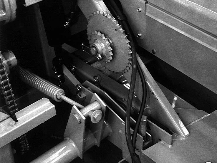
CROP PROCESSOR ROLLER MILL (OPTIONAL)
The two Mill Rolls are the same size and have 4 corrugations per inch. The lower Roll is spring loaded and is in a fixed position while the upper Roll is adjustable. The spring loaded feature reduces the chance of roll damage by allowing small solid foreign objects to pass between the Rolls. Adjustment of the upper Roll is accomplished by unlocking the Chain and turning the Adjustment Wrench in the appropriate direction for finer or coarser processing, as desired. Each full turn of the adjustment handle moves the top Roll 0.20 inch (5 mm). The initial minimum roll clearance is set at 0.020 inch (0.5 mm). The maximum roll clearance is 3.75 inch (95 mm). Each link on the Chain represents a change of 0.010 inch (0.25 mm).

Shifter Transmission Control
The Shifter Transmission (and Electric Clutch) is used to stop the Feed Rolls and the Attachment, to run them forward (to bring the crop into the Cutting Cylinder), or to run the Feed Rolls backwards (to reverse material out of the Feed Roll area). Shifting the Transmission is accomplished by activating Switches on the tractormounted Control Box. Refer to the Operation chapter in this manual for specific details.
Caution
BEFORE leaving the tractor, ALWAYS turn the control box keyswitch to OFF and remove the key and take it with you for your own safety, and to avoid unnecessary drain on your tractor battery.
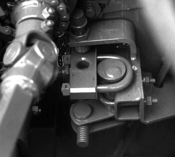
TELESCOPING PTO COUPLER LOCK (Fig. 6)
Both the 1-3/8″ and the 1-3/4″ PTO Telescoping Drives are provided with Spring-loaded Locking Devices on each end for securing the Yokes to the tractor PTO shaft and to the Harvester.
Warning
BE SURE the telescoping PTO connection is properly secured to the tractor PTO shaft BEFORE starting the tractor. Also BE SURE that the telescoping drive shields rotate freely BEFORE starting the tractor.
SAFETY CHAIN (Fig.12)
As required or when desired, the Harvester should be equipped with a safety chain for operation on public highways. See your Gehl dealer for ordering information. The Safety Chain should be attached to the tractor and Harvester as shown.

Caution
ALWAYS follow state and local regulations regarding use of a safety chain and transport lighting when towing farm equipment on public highways. ONLY a safety chain (NOT an elastic or nylon/plastic tow strap) should be used to retain the connection between the towing and towed equipment, in the event of separation of the primary attaching system. BE SURE to check with local law enforcement agencies for your own particular regulations. Unless otherwise prohibited, use a Slow Moving Vehicle (SMV) emblem.
Transport Lighting
A Transport Light Kit is available. Installation details are provided with the Kit. See your local Gehl dealer for details.
Chapter 6 Operation
NOTE: This chapter is divided into three separate sections. The first section pertains to the Harvester. The second section pertains only to the Metal Detector system. The third section pertains only to the Shear Bolt model Harvester.
Harvester
General Information Warning
BEFORE starting the tractor engine and running the Harvester, review and comply with ALL applicable recommendations in the SAFETY chapter.
Emergency Shutdown
In an emergency or in case a foreign object enters or becomes lodged in the Feed Roll area, STOP Harvester operation IMMEDIATELY by disengaging the tractor PTO.
Start-up WARNING
BE SURE ALL Guards and Shields are properly secured in place BEFORE starting the tractor engine and operating the Harvester.
ALWAYS engage the tractor PTO at idle speed when starting the Harvester. Insert the Control Box Key, turn the Power On, start and idle the tractor, engage the PTO, bring the tractor up to rated operating speed, shift to “Forward” when ready to start harvesting.
1.Start PTO at engine idle speed.
2.Increase engine speed to full PTO operating speed.
3.Operate Control Box.
IMPORTANT: To protect the Drive Line components of both the Harvester and the tractor, avoid engaging the tractor PTO at faster than idle speed.
Warning
When any part of the Harvester other than the feed rolls or attachment becomes plugged, stop Harvester operation IMMEDIATELY by moving the feed roll and attachment selector switch to NEUTRAL. Then disengage the tractor PTO and wait for ALL movement to STOP. Next, exercise the MANDATORY SAFETY SHUTDOWN PROCEDURE (page 8). BEFORE leaving the tractor seat to remedy the plugging problem, turn the control box power keyswitch to OFF, remove the key and take it with you.
Crop Processor Roller Mill (Optional)
The purpose of the processor is to increase digestibility and therefore utilization of corn silage by breaking open kernels, and reducing size of cob and stem particles. Machine performance will be best and most efficient if you use the greatest roll clearance and longest length of cut which achieves the desired forage consistency. The amount of processing is directly affected by roll clearance, crop moisture content, and sharpness of rolls. The recommended starting clearance for the rolls is 1/2 turn of the adjustment handle open from the minimum 0.020 inch (0.5 mm). This equals 0.120 inch (3 mm). For finer adjusting, each link on the Chain represents a change of 0.010 inch (0.25 mm).
Although primarily intended for corn processing, this Harvester will also work with hay crops. With the Processor Rolls opened to their maximum (3.75 inch, 95 mm), hay can be harvested. Be aware that any stones or foreign objects will damage the processor rolls. The processor assembly should be removed from the Harvester for normal hay harvest. Refer to the Crop Processor Operator’s Manual for details.
Entering the Crop
NOTE: The PTO should be brought up to the rated 1000 RPM before entering the crop and then maintained at that speed while harvesting.
To maintain the rated RPM, choose the correct tractor gear position to adjust ground speed rather than the tractor throttle. If the tractor engine does bog down, the Speed Monitor will stop the Feed Rolls and allow the engine to regain its speed.
Sharp Cutting Cylinder Knives and proper Shearbar adjustment will provide for more efficient Harvester operation and will reduce horsepower waste.
Leaving the Crop
Maintain the rated RPM for a short time after leaving the crop. This will allow the Harvester Blower, Cutting Cylinder and Deflector to be emptied. After the forage stops coming out of the Deflector, the PTO can be disengaged.
OPERATING FEED ROLLS & ATTACHMENT (METAL DETECTOR MODELS)(Fig. 13)
Move the “AUTO-OFF-MANUAL” Mode Switch to “AUTO” and leave it there. With the Power Keyswitch ON, the Feed Rolls and Attachment are controlled by the FEED ROLLS & ATTACHMENT “SELECTOR” Switch. The “FWD” Switch (in “AUTO”) will NOT operate unless the PTO is operating above approximately 670 RPM. Toggling the Switch to “FWD“ (forward) will immediately cause the Electric Clutch to close and the Feed Rolls and Attachment will run to feed crop into the Knives. Toggling into “NEUTRAL” will open the Clutch and stop all Feed Roll and Attachment motion. To back material out of the Harvester, move the Toggle Switch to “REV” (reverse) and, in addition, rotate and hold the spring-loaded “HOLD FOR REVERSE”

Handle to the right (counterclockwise); release the Handle to automatically open the Clutch and stop reversing.
NOTE: Except for the brief time that the “HOLD FOR REVERSE” Handle is activated, gearing in the Transmission is always in the Forward condition. It has NO neutral. The Neutral condition is created solely by opening the Electric Clutch. The “MANUAL” and “OFF” positions of the Mode Switch are used only when there is a problem with the Automatic circuit. In this mode, the Clutch closes and runs the Feed Rolls and Attachment Forward, when the Switch is toggled to “MANUAL” and the Clutch opens when the Switch is toggled to “OFF” to stop Feed Rolls and Attachment. While operating in MANUAL condition, there is NO Reverse capability, NOR will the Speed Monitor, Metal Stop System or Torque Sensors operate.
NOTE: When operating in the “MANUAL” mode, be extra cautious to avoid plugging the Feed Rolls or the Attachment because the reversing function is inoperative in this mode.
CONTROL BOX FOR TORQUE SENSOR METAL STOP (Fig. 13)
Place the “Auto-Manual” Switch into the “Auto” position and LEAVE IT THERE. This will allow the Auto-Max system to protect the Harvester. No Auto-Max Shut-Off systems will operate with the “Auto-Manual” Switch in “Manual.” The “Manual” Switch position allows the Feed Roll and attachment Drive Torque Sensors to ratchet when they are overloaded. The Torque Sensors may ratchet only a few seconds at a time, but the total accumulative ratcheting life is less than 7 minutes. The “Manual” Switch position should be used as little as possible to avoid damaging the Torque Sensors. The Torque Sensors should never ratchet while the “Auto-Manual” Switch is in “Auto.”
If the Metal Stop System malfunctions and can NOT be repaired immediately, disconnect the Wiring Harness Plug inside the Feed Roll Drive Frame, move the Stop Pawl Spring to the “bypass” position, and keep the “Auto-Manual” switch in “Auto.” Refer to the Metal Stop section in this chapter.
IMPORTANT: Using electrician’s tape, cover the ends of the Plug and Socket to keep dirt out of both parts.
If the Speed Monitor system malfunctions and cannot be repaired immediately, disconnect the Speed Monitor Plug at the Auger Drive and keep the “Auto-Manual” Switch in “Auto.”
If disconnecting the Metal Stop system and the Speed Monitor does NOT allow the Auto-Max system to operate and it can NOT be repaired immediately, proceed as follows. Operate Harvester with the “AutoManual” Switch in “Manual” and shut-off the Feed Rolls and Attachment by moving the “Auto-Manual” Switch to “Off”. The “Manual” Switch position should only be used as a means to finish the day’s work before making repairs. DO NOT use “Manual” Switch all season long.
UNPLUGGING (See Fig. 13)
Warning
When any part of the Harvester other than the feed rolls or attachment becomes plugged, stop Harvester operation IMMEDIATELY by moving the feed roll and attachment selector switch to NEUTRAL. Then disengage the tractor PTO and wait for ALL movement to STOP. Next, exercise the MANDATORY SAFETY SHUTDOWN PROCEDURE (page 8). BEFORE leaving the tractor seat to remedy the plugging problem, turn the control box power keyswitch to OFF, remove the key and take it with you.
Deflector
If the Deflector becomes plugged with chopped forage, proceed as follows:
1.Exercise the MANDATORY SAFETY SHUTDOWN PROCEDURE (as described on page 8).
2.After all Cutting Cylinder and Blower movement has STOPPED, remove the Cleanout Cover from the base of the Deflector.
3.Remove any plugging material which may be wedged inside the Deflector or Deflector Extension through the Cleanout Cover(s).
4.Check and, if necessary, unplug the Blower. Refer to the information under the Blower topic in this chapter, to unplug this area.
Blower
If the Blower becomes plugged with chopped forage, proceed as follows to clear it:
1.Exercise the MANDATORY SAFETY SHUTDOWN PROCEDURE (as described on page 8).
2.Before cleaning out the Blower, wait for the Cylinder to stop turning before proceeding.
NOTE: Even if the Blower Outlet is plugged, the Fan could continue to rotate.
3.The Cleanout Cover at the lower left side of the back of the Blower and the Auger Cover may be opened.
4.After the forage has been cleaned out of the Blower and the Fan turns freely, check the Blower Outlet to insure that it is NOT also plugged.
5.If the Blower Outlet is plugged, use a rod to poke down from the top through the Deflector Cleanout Holes.
6.After the Fan is free to rotate, replace the Cleanout Covers.
Auger
If the Auger becomes plugged with chopped forage, proceed as follows to clear it:
1.Exercise the MANDATORY SAFETY SHUTDOWN PROCEDURE (as described on page 8).
2.Open Auger Cover and clean out the Auger.
3.Close Auger Cover.
4.Replace Shear Bolts if necessary.
5.Refer to the Cutting Cylinder topic in this chapter if the Cylinder is not free to turn.
If the Crop Processor is installed, refer to the Crop Processor topic in this chapter for procedures.
Crop Processor
If the Crop Processor Roller Mill becomes plugged with chopped forage, proceed as follows to clear it:
1.Exercise the MANDATORY SAFETY SHUTDOWN PROCEDURE (as described on page 8).
2.Remove Processor Drive Cover.
3.Release Crop Processor Drive Belt tension.
4.Adjust the Crop Processor Rolls to their greatest clearance position.
5.Open Auger Cover and clean out all crop from the Processor Rolls. If the Cutting Cylinder is plugged, refer to the Cutting Cylinder topic in this chapter.
6.Adjust the Crop Processor Rolls to their operating position.
7.Close Auger Cover.
8.Re–tension Crop Processor Drive Belts.
9.Replace Processor Drive Cover.
Cutting Cylinder
If the Cutting Cylinder becomes plugged with forage, proceed as follows:
1.Exercise the MANDATORY SAFETY SHUTDOWN PROCEDURE (as described on page 8).
2.Inspect the Cylinder by removing the Cover. Check to see if the Knives are wedged with forage. If they are hung up, do the following: a.Pry the Cylinder backward as far as possible so that the Cylinder can build up momentum before it enters the crop. b.If the Crop Processor is installed, clean out all crop from the Processor Rolls. c.Reinstall and secure the Cylinder Cover, Guards, Auger and/or Crop Processor. d.Start the tractor, run the engine at 3/4 to full throttle and engage the PTO to clear the plug; this may partially shear the Main Drive Shear Bolts. e.Again, exercise the MANDATORY SAFETY SHUTDOWN PROCEDURE (as described on page 8) and then check the Cylinder to make sure it is unplugged. f.Inspect the Main Drive Shear Bolts (and replace them, if necessary) following the procedure as described under the “OVERLOAD PROTECTION – Main Drive Line” topic, in this chapter.
Warning
After the cylinder is freed and cleaned out and the main drive shear bolts have been inspected (and replaced), reinstall all guards and covers BEFORE resuming Harvester operation.
3.Insert the Control Box Key, turn the Power On, start and idle the tractor, engage the PTO, bring the tractor up to rated operating speed, shift to “Forward” and resume harvesting.
Feed Rolls
By design, the Feed Rolls allow various mat thicknesses to pass between them. If however, the mat thickness tries to exceed 6″ (152 mm) or if an obstruction gets between the Feed Rolls, the Torque Sensor will detect this condition. This will cause the Electric Clutch to open and stop Feed Roll operation and the crop will NOT feed into the Cutting Cylinder.
When an overload condition does occur, reset the Clutch by setting the Feed Roll & Attachment Selector Switch to NEUTRAL (center position) and then, return it to FWD (forward) position. Do NOT idle the tractor when shifting the Feed Rolls. If the overload condition is NOT cleared by merely resetting the Electric Clutch, move the Feed Roll & Attachment Selector Switch to the REV (reverse position) and rotate the HOLD-FOR-REVERSE Switch to reverse the material back out about 6″ (152 mm). Then, reset the Feed Roll & Attachment Selector Switch to the FWD (Forward position).
NOTE: Special care should be taken so as NOT to reverse the crop too far. Corn should NOT be allowed to back out past the Front Feed Rolls or it will NOT feed back in when the forward mode is re-engaged. Hay should be watched so that the Attachment Auger does NOT “auger” the material sideways and jam it into the Attachment Sidesheets; although it should NEVER need to be backed up that far.
Warning
NEVER hand feed crop into the feed rolls because the crop will feed faster than you can react to let go.
Overload Protection
Main Drive Line (Fig. 14)
The Main Drive is protected from “sudden start” impact damage by Shear Bolts. The Shear Flange is secured with (2) Shear Bolts (5/16 x 2″ Grade 8) with 5/16″ Lock Nuts. The Flange is equipped with a Grease Fitting in the Pilot Area to prevent the Shaft from seizing; the Fitting MUST be greased daily. Additional Shear Bolts are provided in the Toolbox. Additional Shear Bolts can be obtained by ordering 153753 for a package of (eight each) 5/16 x 2″ Grade 8 Shear Bolts and 5/16″ Lock Nuts.

IMPORTANT: ALWAYS use Lock Nuts on Shear Bolts to prevent them from loosening.
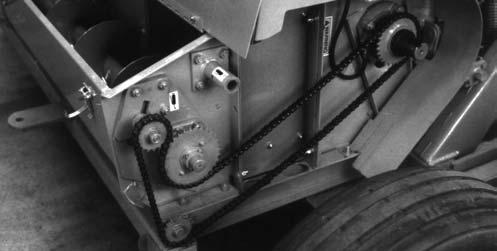
Auger Drive (Fig. )
The Auger Drive is protected by a Shear Flange on the Input Shaft. The Shear Flange is secured with (2) Shear Bolts (1/4 x 1″ Grade 5) with 1/4″ Lock Nuts. Additional Shear Bolts can be obtained by ordering 904400 for a package of (eight each) 1/4 x 1″ Grade 5 Shear Bolts and 1/4″ Lock Nuts. If the Bolt shears, exercise the MANDATORY SAFETY SHUTDOWN PROCEDURE (as described on page 8), remove the cause of the overload and replace the Shear Bolt before attempting to resume harvesting.
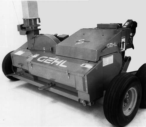
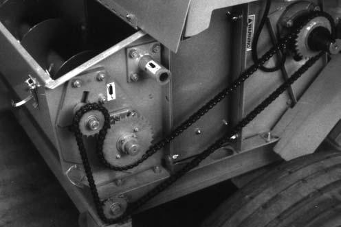
Lower Feed Roll Drive (Fig. 16)
The Lower Feed Roll Drive is protected by a Shear Flange on the Input Shaft. The Shear Flange is secured with (2) Shear Bolts (1/4 x 1-1/2″ Grade 8) with1/4″ Lock Nuts. The Flange is equipped with a Grease Fitting in the Pilot Area to prevent the Shaft from seizing; the Fitting MUST be greased daily. Additional Shear Bolts can be obtained by ordering 080079 for a package of (eight each) 1/4 x 1-1/2″ Grade 8 Shear Bolts and 1/4″ Lock Nuts. If the Bolt shears, exercise the MANDATORY SAFETY SHUTDOWN PROCEDURE (as described on page 8), remove the cause of the overload and replace the Shear Bolt before attempting to resume harvesting.
Control Box (See Fig. 13)

The entire electrical system is protected by Circuit Breakers in the Control Box. To reset a Breaker, clear the trouble in the system first. Then, depress the Breaker Button.
NOTE: After a Breaker is tripped out, it takes about 10–15 seconds before the Breaker can be reset.