CHAPTER 9 SERVICE
WARNING
4 1
BEFORE servicing this unit, exercise the MANDATORY SAFETY SHUTDOWN PROCEDURE (page 8).
NOTE: The following information is referred to in both the Troubleshooting Guide and the Maintenance Schedule chapters of this manual. It should be understood that all services detailed in this chapter are Owner-Operator responsibilities. Where indicated, certain service routines should only be carried out under the direction of an authorized GEHL equipment dealer. Furthermore, all Hydraulic Motors, Hoses and Fittings should be routinely checked after every 100 hours of operation for leaks and secure attachment.
6
5
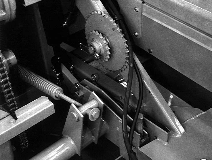
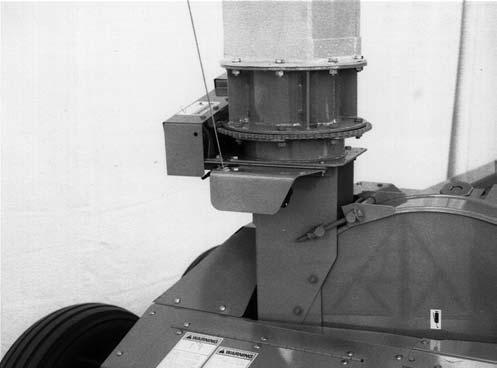
1 – Retaining Washer 2 – Idler 3 – Driven Sheave 4 – Drive Belt 5 – Drive Sheave 6 – Idler Arm
BEVEL GEARBOX IMPORTANT: Internal Bevel Gearbox component repairs and replacements should only be performed by (or under the direction of) an authorized Gehl dealer. The Bevel Gearbox is a mechanism that requires special tools and training to repair; only your Gehl dealer has the facilities and trained personnel to provide this service.
Fig. 49
Drive Sheave (Fig. 49) IMPORTANT: The Bevel Gearbox MUST be removed from the Harvester Frame in order to remove the Drive Sheave. This procedure should be performed by (or under the direction of) an authorized Gehl dealer. Make sure to use thread locking compound on the retaining Bolt.
BLOWER Drive Belt (Fig. 49) The Blower Drive Belt should be checked for cracks, tears and evidence of oil after every 50 hours of operation. To remove the Belt, lift the Idler Arm to relieve Belt tension. The use of a pipe or breaker bar as an aid is suggested. Move the Belt clear of the Idler and then release the Idler Arm tension. Guide the Belt off of the Drive and Driven Sheaves. To install a new Belt, reverse the removal process. Make sure that the new Belt is completely into the Grooves of the Sheaves before lowering the Idler.
908018/AP0499
2
3
Blower Driven Sheave (Fig. 49) Release Drive Belt tension and remove the Belt from the Blower Driven Sheave. Then, remove and retain the Bolt and Washer from the end of the Blower Shaft. The Driven Shaft can now be removed from the Blower Shaft. When reassembling the Sheave onto the Blower Shaft, reinstall the Retaining Washer, Lock Washer and Retaining Bolt using thread locking compound. Tighten the Bolt with 60 to 70 lb–ft (83–95 Nm) torque.
62
Printed in U.S.A.