BI619026
Operation ____________________________________________________ 1. VIEW A -Remove brackets and covers to access the drum drive motor. 2. VIEW B -Remove the capscrews and lock washers that secure the cover for the drive shear shaft. Remove the cover and o-ring. 3. VIEW B -Remove the retaining ring, the plug and the o-ring. Pull the drive shaft out of engagement with the gear case. Replace the shaft cover. Keep the shear shaft in a clean place. 4. VIEW C -Remove the capscrews on the motor junction box cover and remove the cover and o-ring. 5. VIEW D -Mark the motor and power cable leads and disconnect the leads. 6. VIEW E -Remove the stuffing box clamp and slide the power cables out of the motor junction box. 7. Disconnect the cooling water hoses from the motor. Plug the motor and hose ends to keep them clean. The drum drive motor is very heavy. Verify its weight can be supported. 8. VIEW A -Remove the four bolts which mount the drum drive motor to the gear case. 9. VIEW A -Slide the motor out of the gear case. 10. To install a drum drive motor - reverse the above procedure. Be sure to isolate and jog the new motor to check for correct rotation. Note: Reuse top and bottom water manifolds.
drum drive motor dash-2 & dash-3
1. VIEW A -Remove brackets and covers to access the drum drive motor. 2. Remove the torque limiting clutch assembly - follow that procedure. 3. VIEW B -Remove the four capscrews and lock washers on the motor junction box cover and remove the cover and o-ring. 4. VIEW C -Mark the motor and power cable leads and disconnect the leads. 5. VIEW C -Remove the stuffing box clamp and slide the power cables out of the motor junction box. Replace the junction box cover and o-ring.
6. Disconnect the cooling water hoses from the motor. Plug the motor and hose ends to keep them clean. -
C
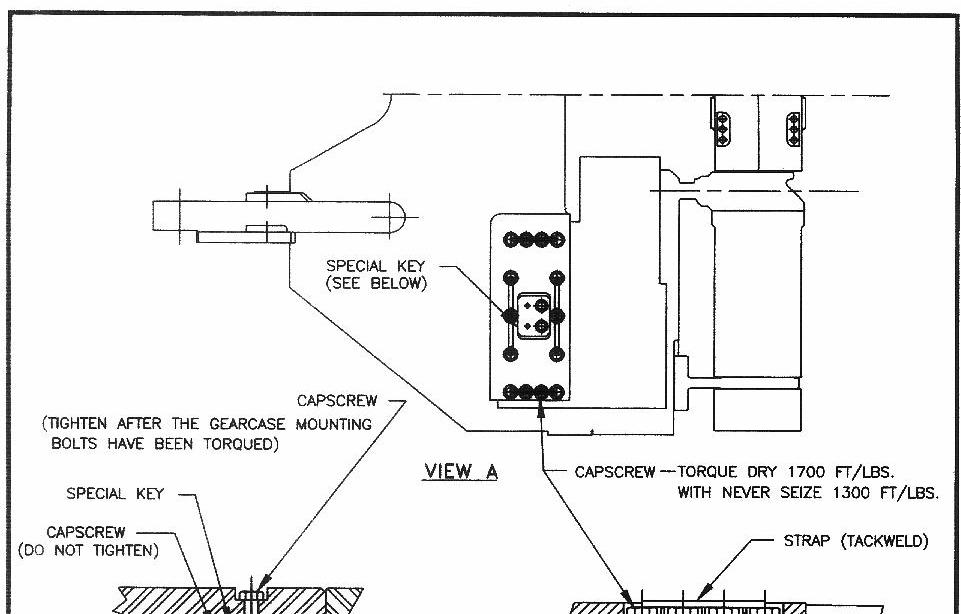
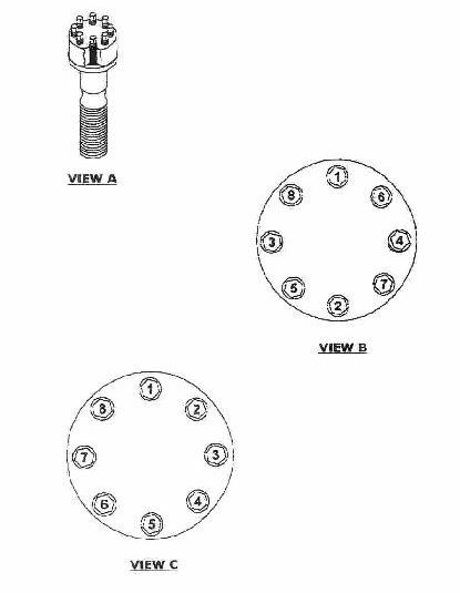
7. VIEW D -Remove the caps from the Superbolts and remove the four Superbolts that secure the drum drive motor to the boom follow the procedure in SUPERBOLT. 8. To install a drum drive motor - reverse the above procedure. Be sure to isolate and jog the new motor to check for correct rotation.
CAUTION
Position the conveyor tail level with the floor. Lower the gathering head to the floor. Raise and block the cutter head assembly. Remove and lock-out the electrical power to the miner.
DANGER
Never work under any raised assembly without proper blocking. The drum drive motor is very heavy. Verify its weight can be supported.
________________________________________________________________ 5.6 VUVR / 03___ DBT – 25M SERIES CONTINUOUS MINER ©
© DBT AMERICA 2005
DANGER