1 minute read
cutter motor feedback adjustment—see figure-59 5

drum drive torque limiting switch
5. VIEW B -Attach the slide hammer to its adapter and pull the boom pivot pin. 6. To install a boom pivot pin - reverse the above procedure.
C
CAUTION
DANGER Position the conveyor tail level with the floor. Lower the gathering head to the floor. Raise and block the cutter head assembly. Remove and lock-out the electrical power to the miner.
Never work under any raised assembly without proper blocking.
drum drive motor dash-0 & dash-1
C
CAUTION
C
CAUTION
DANGER
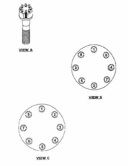
Remove necessary covers to access the clutch at the rear of the cutter motor. 1. VIEW A -Remove the eight capscrews and lockwashers that secures the clutch cover to the motor frame. 2. VIEW A -Remove the clutch cover to expose the clutch assembly. 3. VIEW A -Remove the retaining ring that secures the motor shaft inside the clutch assembly. 4. VIEW A -Pull the motor shaft from the motor and clutch assembly.
Store the motor shaft in a clean place. 5. VIEW B -Remove the sixteen locknuts on the out side of the pressure plate. 6. VIEW B -Remove the pressure plate and the out put hub assembly ( with seal and bearing ) from the clutch. 7. VIEW C -Remove the retaining ring found on the exterior of the keeper plate. 8. VIEW C -Remove the three capscrews and serrated washers that secures the keeper plate to the input hub. 9. VIEW C -Remove the keeper plate and disc spring to reveal the motor shaft secured by a retaining ring.
The remaining clutch assembly is very heavy. Verify the weight
can be supported..
10. VIEW D -Remove the retaining ring from the motor shaft.
The input assembly of the clutch is unattached and can be slipped off the motor shaft. 11. VIEW D -Remove the final retaining ring from the motor shaft. 12. To install the Drum Drive Torque Limiting Clutch - reverse the above procedure.