84 minute read
armature voltage—see figures 60 & 61 5


DANGER
1. VIEW A -Remove brackets and covers to access the drum drive motor. 2. VIEW B -Remove the capscrews and lock washers that secure the cover for the drive shear shaft. Remove the cover and o-ring. 3. VIEW B -Remove the retaining ring, the plug and the o-ring. Pull the drive shaft out of engagement with the gear case. Replace the shaft cover. Keep the shear shaft in a clean place. 4. VIEW C -Remove the capscrews on the motor junction box cover and remove the cover and o-ring. 5. VIEW D -Mark the motor and power cable leads and disconnect the leads. 6. VIEW E -Remove the stuffing box clamp and slide the power cables out of the motor junction box. 7. Disconnect the cooling water hoses from the motor. Plug the motor and hose ends to keep them clean.
The drum drive motor is very heavy. Verify its weight can be supported.
8. VIEW A -Remove the four bolts which mount the drum drive motor to the gear case. 9. VIEW A -Slide the motor out of the gear case. 10. To install a drum drive motor - reverse the above procedure. Be sure to isolate and jog the new motor to check for correct rotation.
Note: Reuse top and bottom water manifolds.
1. VIEW A -Remove brackets and covers to access the drum drive motor. 2. Remove the torque limiting clutch assembly - follow that procedure. 3. VIEW B -Remove the four capscrews and lock washers on the motor junction box cover and remove the cover and o-ring. 4. VIEW C -Mark the motor and power cable leads and disconnect the leads. 5. VIEW C -Remove the stuffing box clamp and slide the power cables out of the motor junction box. Replace the junction box cover and o-ring.
drum drive motor dash-2 & dash-3
C
CAUTION
DANGER
7. VIEW D -Remove the caps from the Superbolts and remove the four Superbolts that secure the drum drive motor to the boom follow the procedure in SUPERBOLT. 8. To install a drum drive motor - reverse the above procedure. Be sure to isolate and jog the new motor to check for correct rotation.
Position the conveyor tail level with the floor. Lower the gathering head to the floor. Raise and block the cutter head assembly. Remove and lock-out the electrical power to the miner.
Never work under any raised assembly without proper blocking. The drum drive motor is very heavy. Verify its weight can be supported.
© DBT AMERICA 2005
shear cylinder dash-0, dash-1 & dash-2
1. Advance the conveyor chain so that a conveyor flight does not block the shear cylinder piston end pin access plate in the conveyor bed.
2. VIEW A -Remove covers to access both ends of the shear cylinder. 3. VIEW B -At the Cutter boom clevis remove two capscrews and lock washers and remove the retaining plate. 4. VIEW B -Using the slide hammer with a 1”-8 adapter pull the pin from the clevis bushing. 5. Connect electrical power to the miner.
C
CAUTION
C
CAUTION
C
Stand clear of the blocked cutter head assembly during contrac-
tion of the shear cylinders..
6. Slowly contract the shear cylinder until the rod comes free from its cutter boom clevis.
Remove and lout-out the electrical power ti the miner.
7. Raise and lower the shear cylinder control lever to release any pressure from the shear cylinder.
8. VIEW C -At the tractor frame clevis, remove the two capscrews and lock washers that secure the pin retaining plate to the frame. Remove the retaining plate.
The shear cylinder is very heavy. Verify its weight can be supported.
CAUTION
9. VIEW C -Using the slide hammer with a 1”-8 adapter pull the pin from the clevis busing.
10. Mark for reconnection then disconnect and cap the hoses to the shear cylinder. 11. The shear cylinder can now be removed. 12. To install a shear cylinder - reverse the above procedure.
shear cylinder dash-3
1. VIEW A -Access both ends of the shear cylinder. 2. VIEW B -At the Cutter boom clevis remove two capscrews and lock washers and remove the retaining plate. 3. VIEW B -Using the slide hammer with a 1”-8 adapter pull the pin from the clevis bushing. 4. Connect electrical power to the miner.
DANGER The shear cylinder is very heavy. Verify its weight can be supported. Remove and lock-out the electrical power to the miner.
5. Slowly contract the shear cylinder until the piston end comes free from its cutter boom clevis.
6. Raise and lower the shear cylinder control lever to release any pressure from the shear cylinder.
7. Mark the hoses for reconnection then disconnect and cap them. 8. VIEW B -At the tractor frame clevis, remove the two capscrews and lock washers that secures the pin retaining plate to the frame. Remove the retaining plate. 9. VIEW B -Using the slide hammer with a 1”-8 adapter pull the pin from the clevis bushing. 10. The shear cylinder can now be removed. 11. To install a shear cylinder - reverse the above procedure.
1. Manually rotate the cutter head drums slowly until the center drum connecting flanges are parallel to the mine floor. .
2. Before you do any disassembly, familiarize yourself with the position of the cutter drum alignment marks / arrows.
cutter drums dash-0
DANGER
center cutter drums
The cutter drums are extremely heavy. Verify its weight can be supported. Remove and lock-out the electrical power to the miner.
1. VIEW A -At the split line of the two halves remove the weld straps using a cutting torch. 2. VIEW A -Remove the twelve capscrews and retainer plates holding the center drum flanges together. Store the capscrews and retainer plates for reinstallation. 3. Attach lifting chains or other lifting device to the top half cutter drum. 4. Break the seal between the center drum’s halves with a pry bar. 5. Lift the upper half of the center drum and move it away from the miner. 6. Connect electrical power to the miner.
© DBT AMERICA 2005
C
CAUTION
7. Raise the cutter head assembly slowly until it is completely clear of the lower half of the center drum and tram the miner away from the drum halves. 8. To Install the center cutter drum - reverse the above procedure.
Remember to torque the twelve capscrews to 1700 lb.-ft. alternating front to back starting from one end and working toward the other.
Verify the lifting device is capable of listing the drum’s weight. Use care when handling the cutter drum.
Follow welding safety instructions.
C
CAUTION
end cutter drums
C
CAUTION
main cutter drums
C
CAUTION
2. VIEW F -Remove the long capscrews and nuts on the two studs which secure the end drum to the cutter drum drive assembly.
3. Remove plug and center drum input shaft. 4. VIEW D -Remove the drum sliding it off of the hub. 5. Remove the key and store for reinstallation. 6. To install the end drum - reverse the above procedure. 7. Be sure the match timing arrows are aligned. 8. VIEW F -Torque the capscrews to 350 lb.-ft.
The end cutter drums are very heavy. Verify the supports can support its weight.
1. The end cutter drum must be removed. Follow that procedure. 2. VIEW E -Using a cutting torch remove the straps tack welded to the strut capscrews. 3. VIEW E -Remove the eight strut capscrews. 4. VIEW F -Remove the remaining nuts on the two studs. 5. Slide the strut and hub assembly from the gear case over the two studs.
6. VIEW B -Remove the capscrews from the main cutter drum..
7. VIEW C -The cutter drum can now be removed from the output shaft by sliding it off the hub and two dowel pins. 8. To install the main cutter drum reverse the above procedure. Apply red loctite and torque the capscrews to 350 lb.-ft.
The main cutter drums are very heavy. Verify the supports can support its weight.
cutter drum installation / removal dash-1
1. Manually rotate the cutter head drums slowly until the center drum connecting flanges are parallel to the mine floor.
2. Before you do any disassembly, familiarize yourself with the position of the cutter drum alignment marks / arrows.
C
CAUTION
DANGER
C
CAUTION Position the conveyor tail section level with the floor. Lower the gathering head until it is level with the floor. Raise and block up the cutter head assembly. Allow for removal of the cutter drums.
The cutter drums are extremely heavy. Verify its weight can be properly supported and use extreme case when handling.
C
CAUTION
center cutter drum
1. VIEW A -At the split line of the two halves remove the weld straps with hammer and chisel. 2. VIEW A -Remove the sixteen capscrews and retainer plates holding the center drum flanges together. Store the capscrews and retainer plates for reinstallation. 3. Attach lifting chains or other lifting device to the top half cutter drum. 4. Break the seal between the center drum’s halves with a pry bar. 5. Lift the upper half of the center drum and move it away from the miner. 6. Connect electrical power to the miner. 7. Raise the cutter head assembly slowly until it is completely clear of the lower half of the center drum and tram the miner away from the drum halves. 8. To Install the center cutter drum - reverse the above procedure.
Remember to torque the sixteen capscrews to 1900 lb.-ft. alternating front to back starting from one end and working toward the other.
© DBT AMERICA 2005
end cutter drums
DANGER
1. Drain the gear case oil before staring to remove the drums. 2. Remove the lock-ring tack welded to the capscrews using a cutting torch. 3. VIEW F -Remove the long capscrews and nuts on the two studs which secure the end drum to the cutter drum drive assembly. 4. Remove plug and center drum input shaft. 5. VIEW D -Remove the drum sliding it off of the hub. 6. Remove the key and store for reinstallation. 7. To install the end drum - reverse the above procedure. 8. Be sure the match timing arrows are aligned. 9. VIEW F -Torque the capscrews to 900 lb.-ft. Tack weld the lockring.
The end cutter drums are very heavy. Verify their weight can be supported. Follow welding safety procedures.
main cutter drums
1. The end cutter drum must be removed. Follow that procedure. 2. VIEW E -Using a cutting torch remove the retainer tack welded to the strut capscrews. 3. VIEW E -Remove the eight strut capscrews. 4. VIEW F -Remove the remaining nuts on the two studs. 5. Slide the strut and hub assembly from the gear case over the two studs. 6. VIEW B -Remove the capscrews from the main cutter. 7. VIEW C -The cutter can now be removed from the output shaft by sliding it off the hub and two dowel pins. 8. To install the main cutter drum reverse the above procedure.
Torque capscrews to 500 lb.-ft. If never size is used reduce the torque value to 300 lb.-ft. ( If loctite is used reduce the torque value to 425 lb.-ft. ) 9. Tack weld the lock-ring and capscrew retainer.
DANGER The strut and hub assemblies are very heavy. Be prepared to supports its weight.
The main cutter drum is extremely heavy. Verify its weight can be
supported..
DANGER
cutter drums dash-2 installation / removal
1. Manually rotate the cutter head drums slowly until the center drum connecting flanges are parallel to the mine floor.
2. VIEW C - Before you do any disassembly, familiarize yourself with the position of the cutter drum alignment marks / arrows. 3. VIEW A -At the capscrews remove the weld straps with hammer and chisel. 4. VIEW C -Remove the twenty capscrews and retainers holding the center drum flanges together. Store the capscrews and connecting plates for reinstallation. 5. VIEW B -Attach lifting chains or other lifting device to the top half cutter drum. 6. Break the seal between the center drum’s halves with a pry bar. 7. 8. VIEW B -Lift the upper half of the center drum and move it away from the miner. 9. VIEW C -Remove the center drum alignment keys from the keyway if the cuttting drums are key driven ( not square drive ). Store for reinstallation. 10. Connect electrical power to the miner. 11. Raise the cutter head assembly slowly until it is completely clear of the lower half of the center drum and tram the miner away from the drum halves. 12. To Install the center cutter drum - reverse the above procedure.
Remember to torque the twenty capscrews to 1850 lb.-ft. alternating front to back starting from one end and working toward the other.
C
CAUTION
DANGER
C
CAUTION
C
CAUTION
C
CAUTION Position the conveyor tail section level with the floor. Lower the gathering head until it reaches the floor. Raise and block the cutter head assembly. Allow space for the removal of the cutter head.
Never work under any raised assembly without proper blocking.
Remove and lock-out the electrical power to the miner. Follow welding safety procedures.
The cutter drums are extremely heavy. Verify the supports willhandle its weight.
Verify the lifting device is capable of lifting the drum;s weight. Use care when handling the cutter drum.
© DBT AMERICA 2005
end cutter drums
1. VIEW D -Remove the weld straps between capscrews using a cutting torch.
2. VIEW D -Remove the twelve capscrews which secure the end drum to the cutter drum drive assembly. 3. VIEW D -Remove the drum from the miner. 4. To install the end drum - reverse the above procedure. 5. VIEW C -Be sure the match timing arrows are aligned. 6. VIEW D -Torque the twelve capscrews to 1200 lb.-ft. Tack weld the straps. C
CAUTION
C
CAUTION
DANGER
C
The end cutter drums are very heavy. Verify the supports can handle its weight. Follow welding safety procedures.
Position the conveyor tail section level with the floor. Lower the gathering head until it reaches the floor. Raise and block the cutter head assembly. Allow for removal of the cutter drums.
Never work under any raised assembly without proper blocking.
Remove and lock-out the electrical power to the miner.
CAUTION
C
CAUTION
1. Manually rotate the cutter head drums slowly until the center drum connecting flanges are parallel to the mine floor.
2. VIEW C -Before you do any disassembly, familiarize yourself with the position of the cutter drum alignment marks / arrows.
The cutter drums are extremely heavy. Use extreme care when handling.
center cutter drum
C
1. VIEW A -At the capscrews remove the weld straps using a cutting torch. 2. VIEW C -Remove the eighteen capscrews holding the center drum flanges together. Store the capscrews for reinstallation. 3. VIEW B -Attach lifting chains or other lifting device to the top half cutter drum. 4. Break the seal between the center drum’s halves with a pry bar. 5. VIEW B -Lift the upper half of the center drum and move it away from the miner. 6. VIEW C -Remove the center drum alignment keys from the key way if the cuttting drums are key driven ( not square drive ). Store for reinstallation. 7. Connect electrical power to the miner. 8. Raise the cutterhead assembly slowly until it is completely clear of the lower half of the center drum and tram the miner away from the drum halves. 9. To Install the center cutter drum - reverse the above procedure.
Remember to torque the eighteen capscrews to 1850 lb.-ft. alternating front to back starting from one end and working toward the other.
CAUTION
C
CAUTION Follow welding safety procedures.
Verify the lifting device is capable of lifting the drum’s weight. Use case when handling the cutter drum.
end cutter drum
C
CAUTION
C
CAUTION
1. VIEW D -Remove the weld straps between capscrews using a cutting torch. 2. VIEW D -Remove the twelve capscrews which secure the end drum to the cutter drum drive assembly. 3. VIEW D -Remove the drum from the miner. 4. To install the end drum - reverse the above procedure. 5. VIEW C -Be sure the timing arrows are aligned. 6. VIEW D -Torque the twelve capscrews to 1200 lb.-ft. Tack weld the strap across the capscrews.
Follow welding safety procedures.
The end cutter drums are very heavy. Verify the supports can handle its weight.
© DBT AMERICA 2005
gear case dash-0 installation / removal
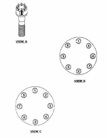
1. Remove the cutter drums - follow that procedure. 2. Remove the covers and water spray manifolds, hosing, and remove cutter motor power leads attached to the gear case. 3. Securely block the cutter drum drive gear case to support it when it becomes separated from the boom. 4. VIEW A -Remove the two capscrews which adjust the special key. 5. Remove the strapping from the capscrews securing the gearcase to the boom using a cutting torch. 6. VIEW D -Remove the fourteen hex head capscrews that secure the cutter drum drive gear case to the cutter drum. 7. Remove the cutter motor. 8. Connect electrical power to the miner. 9. Slowly tram the miner in reverse away from the blocked gear case. 10. VIEW B -Remove the special key and store for installation. 11. To install a gear case - reverse the above procedure. Torque the fourteen capscrews to 1700 lb.-ft.
C
CAUTION
DANGER
C
Position the conveyor tail section level with the floor. Lower the gathering head to the floor. Raise and block-up the cutter head assembly. Allow for removal of the cutter drums.
Never work under any raised assembly without proper blocking.
Remove and lock-out the electrical power to the miner.
The gear case is very heavy. Verify the supports can handle its
weight. .
Stand clear of the gear case and the miner when tramming.
Follow welding safety procedures.
CAUTION
C
CAUTION
C
CAUTION
C
CAUTION
gear case dash-1 installation / removal
1. Remove the cutter drums - follow that procedure. 2. Remove the covers and water sprays attached to the gear case.
Note: Same as Dash Zero.
3. Securely block the cutter drum drive gear case to support it when it becomes separated from the boom. 4. VIEW B -Remove the strapping from the capscrews securing the gear case to the boom using a cutting torch. 5. VIEW B -Remove the sixteen hex head capscrews that secure the cutter drum drive gear case to the cutter drum. 6. Remove cutter motor. 7. Connect electrical power to the miner. 8. Slowly tram the miner in reverse away from the blocked gear case. 9. VIEW B -Remove the two keys and store for installation. 10. To install a gear case - reverse the above procedure. Torque the sixteen capscrews to 1900 lb.-ft.
C
CAUTION
DANGER
C
CAUTION
C
CAUTION
C
CAUTION
C
CAUTION Position the conveyor tail section level with the floor. Lower the gathering head to the floor. Raise and block-up the cutter head assembly. Allow for removal of the cutter drums.
Never work under any raised assembly without proper blocking.
Remove and lock-out the electrical power to the miner.
The gear case is very heavy. Verify the supports can handle its
weight. .
Stand clear of the gear case and the miner when tramming.
Follow welding safety procedures.
© DBT AMERICA 2005
gear case dash –2-3 installation / removal See figures—21 & 22
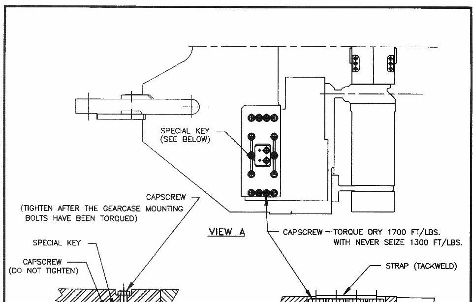
1. Remove the center cutter drum and the end cutter drum - follow that procedure. 2. VIEW A - On the rear of the cutter drum drive motor, locate the clutch housing and the motor shaft access cover plate. 3. VIEW A - Remove the four capscrews that secure the motor shaft access cover plate to the clutch housing. Remove the access cover plate to expose the end of the motor drive shaft. 4. VIEW A - Remove the retaining ring that secures the motor shaft in the clutch assembly. 5. VIEW A - Pull the motor shaft from the motor and clutch assembly. 6. Store the motor shaft in a clean, safe place. 7. To protect the clutch from damage and dirt, replace the access cover plate. . 8. Securely block the cutter drum drive gear case to support it when it becomes separated from the boom. 9. VIEW B -Remove the strapping from the twenty-one capscrews securing the gear case to the boom using a cutting torch. 10. VIEW C - Remove the twenty-one 1 1/4” hex head capscrews that secure the cutter drum drive gear case to the cutter boom. 11. Connect electric power to the miner. 12. Slowly tram the miner in reverse away from the blocked gear case. 13. Remove the three face keys and save for installation. 14. To install a gear case -reverse the above procedure except for the following steps. 15. VIEW D -Insert four 1 1/4” dowel guides into the cutter boom face, spacing them equally over the boom face. 16. VIEW D -Mark the holes on the exterior of the gear case mounting brace that correspond to the positions of the guides on the boom face. 17. VIEW D -Apply RTV silicon sealer to the gear case center alignment key and install the key into the boom face. Also install the gear case’s two larger side alignment keys into the boom face. 18. VIEW C -Torque the twenty-one capscrews to 1850 lb.-ft. beginning with the inner capscrews and working to the outside.
Remember to fill the gear case with approved lubricant.
C
CAUTION
C
CAUTION
DANGER
C
CAUTION Position the conveyor tail section level with the floor. Lower the gathering head to the floor. Raise and block-up the cutter head assembly. Allow for removal of the cutter drums. Remove and lock-out the electrical power to the miner.
The gear case is very heavy. Verify the supports can handle its weight. Stand clear of the gear case and the miner when tramming
Never work under any raised assembly without proper blocking.
Follow welding safety procedures.
cutter boom dash-0 gear case—Figure 21
© DBT AMERICA 2005

cutter boom dash-1 gear case—Figure 22
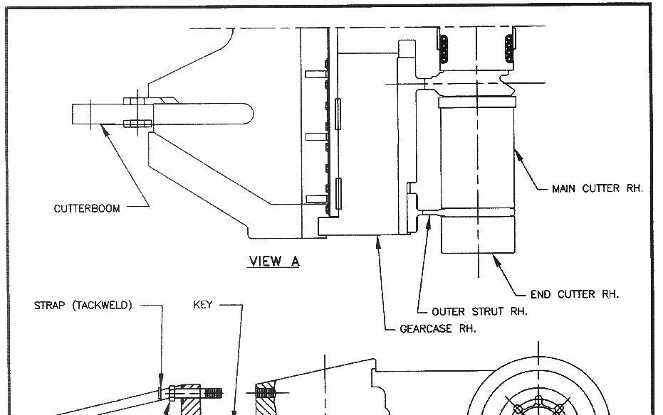

cutter boom dash-2, 3 gear case

© DBT AMERICA 2005
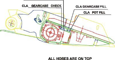
gathering head ass’y installation / removal See figure—14 & 15
The gathering head assembly has two Continuous Loading Arms ( CLA ) which rotate to load the cut material on to the conveyor. Two electric motors drive the CLA gear cases and the conveyor foot shaft. The electric motors are called either “gathering head” or “conveyor” motors.
1. View A - Place blocking under the rear of the gathering head to stabilize its position during and after the removal of the pivot pins and disconnection of the lift cylinders. 2. Remove the electric motor cable and cooling water lines from the gathering head. Disconnect these from the motor. Refer to the motor removal procedure. 3. View B - Access the gathering head pivot point by removing the forward tram rub rail. 4. View C - Remove the two 3/4” capscrews and lock washers that secure the pin retaining plate to the tractor frame. 5. View C - Remove the two 1” capscrews and lock washers that secure the pin retaining plate to the pivot pin. 6. View D - Using the slide hammer with a 1”-8 adapter remove the pivot pin. 7. Repeat steps 3 through 7 for the opposite side. 8. Disconnect both lift cylinders from the gathering head by pulling the piston end pins. Refer to the lift cylinder replacement procedure. 9. Lower the gathering head control lever at the valve bank. The weight of the lift cylinder pistons should cause the piston ends to come free from the gathering head. 10. Connect electrical power to the miner. 11. View E - Lift the cutter head off of the blocking and slowly tram the miner in reverse until the cutter head clears the backboard of the gathering head. 12. To install the gathering head - reverse the removal procedure.
C
CAUTION Lower the conveyor tail until it is level with the floor. Lower the gathering head until it rests on the floor. Raise and block up the cutter head assembly. Remove and lock-out electrical power to the miner. Be sure to tape up the motor cable leads. There will be electric power on the miner before the motors are reconnected.
Check the blocking of the gathering head assembly so it w ill not drop w hen the pivot pins are removed and the lift cylinders are disconnected. W hen separating the gathering head from the tractor frame, insure that the disconnected ends of the conveyor chain slide out of the gathering head.
Never work under any raised assembly without proper blocking.
C
CAUTION
DANGER
CLA installation / removal See figure—16
1. View A - Remove the three 1” capscrews and lock washers where the arms meet the CLA hub. 2. View A - Remove the six 1” capscrews and lock washers located in the center of the CLA hub. The CLA should now be free and able to be removed. 3. View B - Remove the four CLA alignment keys from the exposed gathering head gear case turntable. Store the keys in a safe place. 4. View C - On installation of the CLA, mark the outer bolt hole on the
CLA that is directly adjacent to a key cut-out. Place a 1” wooden dowel in the outer bolt hole of the gear case turntable that is directly adjacent to a key cut-out. Place the four keys into their cut-outs on the gear case turntable. 5. View D - Place the CLA on the gear case turntable so that the dowel extends through the marked CLA hole. Adjust as necessary to fit the turntable keys into the CLA cut-outs. 6. View D - Remove the wooden dowel and install the nine lock washers and capscrews. If hog rings are used, they should be installed so that their sharp points prevent the capscrew from loosening per
View E. 7. After CLA installation, inspect the positions of the CLAs to insure that the arms will not collide during rotation.
C
CAUTION Lower the conveyor tail until it is level with the floor. Lower the gathering head to the floor. Raise and block up the cutter head assembly. Remove and lock-out electrical power to the miner.
Never work under any raised assembly without proper blocking.
DANGER
© DBT AMERICA 2005
gathering head motor installation / removal
1. View A - Remove the side cover secured by two capscrews and lock washers. The end of the motor will be exposed. 2. View B - Remove the 2” pipe plug on the end of the motor. Using a screwdriver remove the retaining ring that secures the shaft end plug inside the motor housing. 3. View B -Pull the drive shaft out using a slide hammer with a 3/8”-16 adapter. Store the drive shaft, shaft end plug and the retaining ring in a safe place. Replace the pipe plug in the end of the motor. 4. View D - Disconnect and plug the water connections. 5. View E - Remove the four 3/4” socket head capscrews that secure the motor to the gear case adapter plate. The motor can now be pulled out to get to the junction box. Note the seal between the motor and the gear case. 6. View C -Disconnect the electrical cables in the junction box. Mark the cable motor leads so they can be reconnected correctly. Remove the stuffing box clamp and pull the cable out of the motor. 7. To install a motor - reverse the above removal procedure. Use a new seal between the motor and the gear case. 8. A newly installed motor must be run independent of the other motor to insure proper rotation. This can be done by isolating the other motor in the controller case.
C
CAUTION Verify electrical power to the miner is disconnected and lockedout.
foot shaft installation / removal
DANGER
C
CAUTION
1. View A -Slowly advance the conveyor chain until a connecting link appears at the gathering head foot shaft area.
2. Loosen the conveyor chain tension as much as possible. ( See
Conveyor Chain Adjustment Procedure.) 3. View A - Remove the conveyor chain connecting link. 4. View B -Remove the eight 3/4” capscrews and lock washers securing the footshaft cover to the gathering head. 5. View C -Remove the four 1/2” capscrews from each of the two collars and remove the collars from the footshaft. 6. View D -Slide the two couplings from the ends of the footshaft toward the center sprocket on the footshaft. 7. View E - The footshaft can now be removed. 8. To install the footshaft - reverse the above removal procedure. 9. Be sure to readjust the conveyor chain tension.
Never work under any raised assembly without proper blocking.
Verify power to the miner is disconnected and lock-out.
gear case installation / removal
1. Completely drain the gear case lubricant by removing the two 3/4” plugs located on the underside of the gear case. Replace the drain plugs. 2. Reconnect electrical power and lower the gathering head assembly to the floor. 3. Remove the CLA ( Follow that procedure.) 4. Remove the drive motor. ( Follow that procedure. ) 5. Remove the footshaft. (Follow that procedure.) 6. View A - Remove capscrews and the upper and lower deck covers. 7. View B -Disconnect the four lubrication hoses from the gear case.
Tag the hoses so they can be reconnected properly. Plug both ends to keep dirt out. 8. View C - Remove the twelve capscrews that secure the gear case pot and mounting wedges to its mounting plate. 9. The gear case can now be removed. 10. To install a gear case -Reverse the removal procedure. Use a new gear case-to-motor seal. 11. Fill the gear case. Attach a rose gun to the lower port located next to the gathering head side cover and fill the gear case to the proper level with gear lubricant. The gear case is full when steady oil flow is observed from the breather plug in the top port. Check for leaks.
C
CAUTION
DANGER
NOTICE Lower the conveyor tail until it is level with the floor. Raise and block up the cutter head assembly. Raise and block up the gathering head assembly. Remove and lock-out electrical power to the miner.
Never work under any raised assembly without proper blocking.
The cutter head assembly should still be blocked up.
© DBT AMERICA 2005
1. View A - Remove two capscrews and the Piston Pin Retaining Bar. 2. View A -Use the slide hammer with a 5/8”-11 adaptor to pull the
Piston Pin from the clevis bushings. 3. Lower the gathering head control lever at the valve bank. The weight of the lift cylinder piston should cause the piston end to come free of its clevis. 4. Move the gathering head lift cylinder control lever up and down to release any pressure from the lift cylinder. 5. View C - Remove the hydraulic hose from the lift cylinder’s hydraulic fitting. Plug the hose end to keep it clean. 6. View D -Remove the two capscrews that secure the Pin Retaining
Plate to the tractor frame. Remove the Pin Retaining Plate. 7. View D - Use the slide hammer with a 5/8”-11 adapter to pull the rod end pin from the frame cleves bushing. 8. The lift cylinder can now be removed. 9. To install the lift cylinder - reverse removal procedure.
C
CAUTION
DANGER
WARNING Lower the conveyor tail until it is level with the floor. Raise and block up the cutter head assembly. Raise and block up the gathering head assembly. Remove and lock-out electrical power to the miner.
Never work under any raised assembly without proper blocking. Stand clear of the blocked cutter head and gathering head assemblies.
Be prepared to support the cylinder when it becomes free.
tractor frame ass’y See figure—1
The maintenance procedures for the tractor frame assemblies are basically the same for all of the Dash Series miners.
The installed tram case includes the tram motor, the tram primary planetary gear, the tram reach gear set, the tram secondary planetary gear, and the tram sprocket. Removal of the tram case is a major undertaking involving the removal of crawler track pads from the tram case. Depending upon the maintenance required removal / installation procedures are given for each major component.
For detail disassembly and assembly and to identify parts of the tram gear case refer to the assembly drawing in the parts book for that miner.
1. VIEW A - Remove the tram rub rail after pulling the two tram rub rail pins. 2. VIEW B - Remove the four hex head capscrews and lock washers that hold the input shaft access cover to the motor frame. Remove the input shaft access cover and o-ring. 3. VIEW B - Remove the retaining ring, shaft plug & o-ring and pull out the motor input shaft. Replace the input shaft access cover. 4. VIEW C - Disconnect the cooling water hoses from the motor. Plug the hoses and fittings to keep them clean. 5. VIEW D - Remove the four capscrews that hold the tram motor bracket to the tram case. Remove the tram motor bracket. 6. VIEW D -Slide the tram motor out from the tram case until the electrical connection and hand hole cover are accessible. Remove the eight capscrews that hold the hand hole cover to the motor frame. Remove the hand hole cover and o-ring. 7. VIEW D - Mark the wire connections and disconnect the power cables. Remove the two capscrews that hold the stuffing boxes half moon clamp to the junction box. Slide the stuffing box out of the junction box. On the Dash Zero remove the scrubber duct mounting bracket also. 8. VIEW E -Slide the tram motor out from the tram case onto blocking.
Take care not to damage the motor adapter plate seal. 9. To install the tram motor - reverse the above removal procedure.
Note: Slide the input shaft through the tram motor (VIEW B) and into the tram planetary primary gear -The input shaft end without the threaded hole should be inserted first. It may take some adjusting to get the splined end of the shaft to fit into the gear spline. Be sure to install a new motor-to-adapter seal.
C
CAUTION LOWER THE GATHERING HEAD AND CUTTER HEAD TO THE FLOOR. POSITION THE CONVEYOR TAIL SECTION LEVEL WITH THE FLOOR. REMOVE AND LOCK OUT ELECTRICAL POW ER TO THE MINER. DO NOT RECONNECT ELECTRICAL POWER TO THE MINER WHILE THE TRAM MOTOR POWER CABLE IS DISCONNECTED.
© DBT AMERICA 2005
1. VIEW A - Remove the tram motor. ( Follow that procedure )
The tram primary planetary gear is located behind the tram motor. 2. VIEW B - Remove the sixteen capscrews that secures the motor adapter plate and the primary gear ring to the tram case. 3. Remove the motor adapter plate from the gear case. 4. Carefully slide the primary planetary carrier assembly out of the primary gear ring and remove the assembly from the tram case. 5. Carefully slide the primary gear ring out of the tram case. 6. Installation of the primary planetary gear set - Reverse the above procedure using the following installation steps. 7. VIEW B - Insert alignment dowels inserted into four (4) of the sixteen (16) capscrew holes in the tram case. 8. VIEW B -Mark the mounting holes of the primary planetary gear ring that correspond to the holes in which the alignment dowels were placed. 9. VIEW B - Carefully insert the primary planetary gear assembly into the gear ring. Be sure that the extension of the sun gear faces out from the center of the miner and that the internal gear teeth of the primary carrier are seated securely onto the tram drive pinion gear. Orient the adapter plate with the adapter dowels along the bottom edge. 10. VIEW B - Install and tighten the sixteen 3/4” capscrews to 230 lb.-ft. Remove the alignment dowels as you proceed.
C
CAUTION
IMPORTANT Lower the gathering head and the cutter head to the floor. Lower the conveyor tail section. Remove and lock-out electrical power to the miner.
Recommended to replace input seal.
1. VIEW A - Remove the tram rub rail after pulling the two pins. 2. VIEW B - Remove the 3/4” plug from the bottom of the secondary planetary gear cove and drain the lubricate from the gear case.
Replace the plug. 3. VIEW C - Remove the 16 capscrews that hold the secondary planetary gear cover to the tram case. 4. Remove the secondary planetary gear thrust washer from the planetary gear cover. 5. VIEW D -Slide the secondary planetary gear ring off the secondary planetary gear assembly. 6. VIEW D -Install eight 3/4” - 10x2 1/2” hex head capscrews into the sprocket bearing carrier to hold it on the tram case. 7. VIEW E - Pull the secondary tram gear shaft from the gear and sprocket. 8. VIEW F -Carefully slide the secondary planetary assembly out of the sprocket bearing carrier. 9. VIEW G - Installing the secondary planetary assembly is basically the reverse of the above procedure, except for the following. 10. Slide the secondary tram drive shaft with the thread hole end to the outside into the tram drive sprocket and reach gear set. The shaft may require some adjustment to introduce the splined end into the reach gear. 11. Insert four alignment dowels into the holes in the sprocket bearing carrier. 12. To facilitate ring gear insertion, mark the mounting holes of the secondary planetary ring gear that corresponds to the holes in which the alignment dowels were placed. 13. Carefully slide the secondary planetary ring gear onto the four alignment dowels so that the dowels appear through the marked holes. The planetary should slide smoothly into the ring gear teeth. 14. Place a new thrust washer into the secondary planetary cover.
The side of the thrust washer with the inscribed circles should face away from the drive shaft. 15. To facilitate the gear cover replacement, mark the mounting holes of the secondary planetary gear cover that corresponds to the holes in which the alignment dowels are placed. NOTE: The flat edge of the cover located adjacent to the 3/4” lubrication fitting is the top of the cover. 16. Slide the secondary planetary gear case cover onto the alignment dowels so that the dowels appear through the marked holes. 17. Using the 5/8” torque wrench, install and torque all sixteen capscrews to 220 ft.-lb., removing the alignment dowels as you proceed. 18. Fill the secondary planetary gear case to the proper level with the recommended lubricant. Allow the lubricant level to stabilize and recheck it several times before operation.
C
CAUTION Lower the gathering head and the cutter head to the floor. Lower the conveyor tail section. Be prepared to support the heavy weight of the secondary planetary ring gear when removing it from the secondary planetary assembly. Be prepared to support the heavy weight of the secondary planetary gear assembly when removing it from the sprocket bearing carrier in the tram case.
© DBT AMERICA 2005
tram case installation / removal See figure—5 & 6
1. VIEW A - Place blocking under the cutter head assembly and raise the front of the miner and use the stabilizer jack to raise the rear of the miner. Place blocking in multiple locations under both crawler tracks. When the miner is lowered, the weight of the miner rests on the tram track blocking. Leave the blocking under the cutter head; the crawlers will be raised off their blocking later.
2. VIEW B - Remove the tram rub rail after removing the two tram rub rail pins. 3. VIEW B - Open the front rub rail after removing the capscrew holding it in place. 4. VIEW C - Use a grease gun to extend the take-up jack to remove the pusher plate pressure and remove the idler adjustment shims, 5. VIEW C - Open the pressure release valve on the take-up jack to allow the cylinder to contract. This will loosen the tension on the crawler chain. 6. VIEW D -Disconnect the tram crawler pads near the track entry opening by removing the two roll pins that hold the crawler pins in the crawler pads. 7. VIEW D - Attach heavy wires to the end of the crawler track link that passes through the tram case and over the tram sprocket. 8. If the tram drive is operational reconnect electrical power to the miner. 9. VIEW E -Slowly operate the tram motor forward to rotate the sprocket so that the end of the tram track that passes through the case and rolls off the sprocket.
10. VIEW E -Pull the tram track from the front of the miner ( near the idler ) so that the free end of the tram track is pulled clear of the tram case exit opening. 11. VIEW F -Remove the two 1-1/4”x 3-3/4” lg. Superbolts from the sprocket side of the tram case and the two 1-1/4”x 3-3/4”
Superbolts from the motor side of the tram case. Follow the
SUPERBOLT installation / removal procedures. 12. VIEW F - Remove the two 1-1/4”x 5” Superbolts from the sprocket side of the tram case and the two 1-1/4”x5” Superbolts from the motor side of the tram case. Remove the two capscrews from the sprocket side of the tram case. 13. Follow the TRAM MOTOR removal procedure to disconnect the tram motor power cable and cooling water hoses. 14. VIEW G -Slide the tram case out from the tractor frame onto blocking. Pull the tram track guide wires out of the tram case exit opening and secure the wires to the tractor frame. 15. To install the tram case - reverse the above procedure. 16. VIEW H - Check the tram track tension when the crawlers are off the floor. The track sag should be between 2-1/2” and 3-1/2”. If the tram track is not at the proper tension follow the adjustment procedure in TRAM TRACK.
DANGER Never work under any raised assembly without proper blocking.
Remove and lock-out electrical power to the miner. Stand clear of the miner w hen using the tram motor to remove the tram track from the sprocket. The assembled tram case is very heavy. Be prepared to support the tram case before removing it from the tractor frame.
C
CAUTION
DANGER
C
CAUTION
1. VIEW A - Place blocking under the conveyor tail section. Place blocking under the cutter head assembly. Lower the gathering head onto blocking. Lower the conveyor tail section onto blocking. 2. VIEW A - Pressure down the cutter head to raise the front of the miner. Pressure down the stabilizer to raise the rear of the miner.
Place blocking in multiple locations under both tracks. Add blocking under the tractor frame. 3. VIEW A -Raise the cutter head and the stabilizer until the weight of the miner is on the blocked up tracks and tractor frame. 4. Remove the blocking from under the stabilizer shoe. 5. VIEW B -Reference for horizontal mounted stabilizer cylinder on
Dash One, Dash Two, and Dash Three miners. VIEW C -
Reference for vertical mounted stabilizer on Dash Zero miners. 6. VIEW B / C - With the stabilizer shoe resting on the ground, remove the capscrews securing pins at the cylinders rod end clevis. 7. VIEW B / C - Remove the rod end pin using a hammer and punch. 8. Connect electrical power to the miner. 9. Contract the stabilizer cylinder. The rod end bearing of the cylinder should remove itself from its clevis. 10. Raise and lower the stabilizer cylinder lever to release any pressure from the stabilizer shoe lift circuit. 11. Disconnect the hydraulic hoses from the stabilizer cylinder. Mark the hoses and plug them to keep them clean. 12. Remove and cap the hydraulic fittings from the cylinder. 13. VIEW B / C - Remove the cotter pins or capscrews used to secure the cylinder pin at the tractor frame clevis. 14. VIEW B / C - Remove the cylinder pin at the tractor frame using a hammer and punch. 15. To install a stabilizer cylinder - reverse the above procedure. 16. VIEW D - If both stabilizer cylinders have been removed, The stabilizer shoe can be removed by removing the two pivot pins at the tractor frame.
Never work under any raised assembly without proper blocking.
Remove and lock-out electrical power to the miner. Be prepared to support the heavy stabilizer cylinder.
© DBT AMERICA 2005
1. VIEW A - Place blocking under the cutter head assembly and raise the front of the miner and use the stabilizer jack to raise the rear of the miner. Place blocking under both crawler tracks. Lower the miner onto the crawlers. Leave the blocking under the cutter head; the crawlers will be raised off their blocking later.
2. VIEW B - Remove the tram rub rail after removing the two tram rub rail pins. 3. VIEW B - Open the front rub rail after removing the capscrew holding it in place. 4. VIEW C - Use a grease gun to extend the take-up jack to remove the pusher plate pressure and remove the idler adjustment shims. 5. VIEW C - Open the pressure release valve on the take-up jack to allow the cylinder to contract. This will loosen the tension on the crawler chain. 6. VIEW D -Disconnect the tram crawler pads near the track entry opening by removing the two roll pins that hold the crawler pins in the crawler pads. 7. VIEW D - Attach heavy wires to the end of the crawler track link that passes through the tram case and over the tram sprocket. 8. If the tram drive is operational reconnect electrical power to the miner. 9. VIEW E - Slowly operate the tram motor forward to rotate the sprocket so that the end of the tram track that passes through the case rolls off the sprocket.
10. VIEW E - Pull the tram track from the front of the miner (near the idler) so that the free end of the tram track is pulled clear of the tram case exit opening. 11. VIEW F - Remove the tram secondary planetary gear - follow that procedure. 12. VIEW G - Remove the outboard sprocket bearing carrier using puller holes provided. 13. Using a scoop or other pulling equipment pull the sprocket assembly from the case. The rear bearings and seals should come out with the sprocket. 14. Removal is complete. 15. To install the tram sprocket, reverse the above procedure. 16. VIEW H - Check the tram track tension while the crawlers are off the floor. The track sag should be between 2-1/2” and 3-1/2”. If the tram track is not at the proper tension follow the adjustment procedure in TRAM TRACK.
IMPORTANT
DANGER
C
CAUTION The Tram Sprocket Assembly is provided with new bearings seals and O-rings.
Never work under any raised assembly without proper blocking.
Remove and lock-out electrical power to the miner. Stand clear of the miner when using the tram motor to remove the tram track from the sprocket. Be prepared to support the weight of the sprocket.
tram track adjustment See figure—9
1. Raise the tractor frame off the blocking by lowering the stabilizer and gathering head and cutter head assemblies.
2. VIEW A - Lower the conveyor tail section on to blocking. 3. VIEW A - Raise the gathering head and cutter head and place a small stack of blocking under these two assemblies. 4. VIEW A - Lower the cutter head onto the blocking so that the front of the miner lifts off the floor. 5. VIEW A - Extend the stabilizer completely so that the rear end of the miner lifts off the floor. 6. VIEW A - Place blocking under the tractor frame in multiple locations. The blocking must not interfere with the tram track. 7. VIEW A - Raise the stabilizer and the cutter head and lower the tractor frame securely on to blocking. 8. VIEW B - Remove the capscrew and lock washer that secures the front rub rail to the tractor frame and open the front rub rail cover. 9. VIEW C - Evaluate the tram track for proper tension. The tram track is at the proper tension when it hangs approximately 2 1/2” to 3 1/2” from the bottom wear shoes when the tractor frame is blocked off the floor. Check both sides. 10. VIEW D - IF THE TRAM TRACK IS TOO TIGHT, re-adjust the idler position using the following steps:
¢ Pump grease into the take-up jack to extend the cylinder and remove pusher plate pressure on the idler shims. ¢ Remove one or more idler adjustment shims from the idler slide channel. ¢ Open the pressure release valve for the front idler take-up jack and allow the jack to contract. The pusher plate will slide backwards until it is stopped by the remaining idler shims. ¢ Evaluate the resulting track tension and repeat these steps until the track reaches proper tension.
IMPORTANT If the tram track is too loose, re-adjust the idler position using the following steps:
¢ Pump grease into the idler take-up jack to extend the cylinder, move the idler assembly forward, and tighten the tram track until it is at the correct tension. The tram track is at the proper tension when it hangs 2 1/2” to 3 1/2” from the bottom wear shoes when the tractor frame is blocked off the floor.
¢ Insert shims into the idler slide channel until the space between the tractor frame and the pusher plate is filled.
¢ Check that the shims are correctly seated on the idler slide channel’s inside surface by looking at the channel’s inside surface from the opposite side of the miner, through the space between the gathering head and the idler assembly.
© DBT AMERICA 2005
¢ Open the pressure release valve for the front idler takeup jack and allow the cylinder to contract. The idler adjustment shims will keep the idler stationary and the track tensioned.
¢ Evaluate the resulting track tension and repeat these steps until the track reaches proper tension.
IMPORTANT If the tram track tension is still too loose when the entire 5” shim set if inserted into the idler slide channel, re-adjust the idler position after removing a tram track link using the following steps:
¢ Pump grease into the take-up jack to extend the cylinder and remove pusher plate pressure on the idler shims. ¢ Remove all of the idler adjustment shims from the idler slide channel. ¢ Open the pressure release valve for the front idler takeup jack and allow the jack to contract. The pusher plate and idler assembly will slide backwards. 1. VIEW E - Locate a tram track link near the idler. Using the hammer and punch, remove the four roll pins of the two tram track pins that secure the tram track link to the track.
2. Remove the tram track pins to disconnect the link from the track. Remove the disconnected link.
3. Store the tram track link, one of the tram track pins, and two of the roll pins in a safe place.
4. Having removed one link reconnect the tram track.
11. Repeat the previous procedures. 12. VIEW D -When the tram track has been adjusted to the proper tension, remove the grease gun from the idler take-up jack grease fitting. 13. VIEW B -Close the front rub rail cover and replace capscrew and lock washer to secure the front rub rail to the tractor frame. 14. Connect the electrical power to the miner.
NOTICE Shims must be inserted completely into the idler slide channel. A shim that is not correctly seated on the idler slide channel’s inside surface provides uneven support that can cause idler slant. A slanted idler can cause uneven wear and stress on the tram track and can cause improper operation of, or damage to, the tram system. The tram track tension should now be reduced and separation of the tram track will be easier.
Remove and lock-out electrical power to the miner. Stand clear of the miner when raising it off the support blocking. Carefully remove the support blocking from under the miner.
Never work under any raised assembly without proper blocking.
C
CAUTION
DANGER
DANGER
NOTICE
1. VIEW A - Raise the gathering head and cutter head assemblies to their highest points and place blocking underneath. Lower the assemblies onto the blocking. 2. VIEW B - Remove the capscrew and lock washer that secure the front rub rail to the tractor frame. Open the front rub rail cover. 3. VIEW C - Locate the idler take-up jack grease fitting and attach the grease gun to the fitting. Pump grease into the take-up jack to extend the cylinder and remove pusher plate pressure on the idler adjustment shims. 4. VIEW C - Remove all of the idler adjustment shims from the idler slide channel and store the shims in a safe place. 5. VIEW D -Open the pressure release valve for the front idler take-up jack and allow the jack to contract. The pusher plate and idler assembly will slide backwards. 6. VIEW E - Locate a tram track link near the tram front idler. Using a hammer and punch, remove the two roll pins that secure the tram pin between the links. Store the roll pins in a safe place. 7. VIEW E - Using a hammer and punch, remove the tram track pin to disconnect the links and separate the track. Store the track pin in a safe place. 8. VIEW F - Slide the front idler assembly out of the idler slide channel. 9. To install the tram track front idler, reverse the above procedure.
Never work under any raised assembly without proper blocking.
The gathering head and cutter head must be blocked high enough to allow the idler assembly to be removed from the tractor frame’s idler slide channel.
© DBT AMERICA 2005
C
CAUTION
1. VIEW A - Remove the capscrew and lock washer that secure the front rub rail to the tractor frame and open the front rub rail cover. 2. VIEW B - Pull the flip pin from the half link to release the take-up jack bracket from the tractor frame. 3. VIEW C -Lower the end of the bracket until it clears the half link and pull the bracket straight out to remove it from the tractor frame. 4. To install the front idler take-up jack assembly - reverse the above procedure.
Lower the gathering head and the cutter head to the floor. Lower the conveyor tail section. Remove and lock-out electrical power to the miner.
DANGER
NOTICE
C
CAUTION
1. VIEW A—Remove or open the rub rail to the rear of the tram rub rail on the left side (scrubber exhaust side) after pulling the two rub rail pins. 2. VIEW B—Disconnect the hoses from the pump and plug then to keep dirt and dust out. 3. VIEW C—Remove the hose fittings from the pump and store in a clean location. 4. VIEW D—Remove the capcrews (usually more than two each) that secure the hydraulic pump to the electric motor. 5. To install the hydraulic pump - reverse the above procedure.
The following procedure involves disconnecting hydraulic hoses. They can be under high pressure.
Take special care to prevent coal dust and mine dirt from getting into the hydraulic system when removing any hydraulic component.
Lower the gathering head and the cutter head to the floor. Lower the conveyor tail section. Remove and lock-out electrical power to the miner.
1. VIEW A -Remove or open the rub rail to the rear of the tram rub rail on the left side (scrubber exhaust side) after pulling the two rub rail pins. 2. VIEW B -Remove the hydraulic pump - follow that procedure. 3. VIEW C -Remove the capscrews (usually more than two each) that mount the pump stand to the frame. 4. VIEW D -Disconnect the two cooling water hoses from the fittings on the pump motor. Remove the fittings. Plug the hose ends and motors inlets to keep them clean. NOTE: The motor may need to be partially slid out to access the hoses and junction box. 5. VIEW D -Remove the four capscrews that hold the junction box cover and o-ring in place. This will permit access to the wiring connections. 6. VIEW E -Mark the three wires, strip off the insulation tape and disconnect the three power cable lugs from the three motor lugs. 7. VIEW F -Remove the capscrews holding the half moon clamp to the junction box. Slide the stuffing box out of the junction box. 8. VIEW G -Take care as the motor is slid out from the tractor frame on to blocking. 9. To install the pump motor - reverse the above procedure. Be sure to jog the motor on and off to determine correct rotation.
DANGER
NOTICE
C
CAUTION The following procedure involves disconnecting hydraulic hoses. They can be under high pressure.
Take special care to prevent coal dust and mine dirt from getting into the hydraulic system when removing any hydraulic component.
Lower the gathering head and the cutter head to the floor. Lower the conveyor tail section. Remove and lock-out electrical power to the miner. Remember the pump motor is very heavy.
© DBT AMERICA 2005
conveyor assembly installation / removal See figures 38 & 39
1. VIEW A -Position the conveyor tail section level with the floor and straight. Advance the conveyor chain until a connecting link moves onto the tail section slide pan.
2. VIEW B - Using the procedure outlined in CHAIN TENSION, loosen the conveyor chain as much as possible. 3. VIEW C - Remove the two retaining rings and the connecting link. 4. VIEW D - Connect a wire rope to the bottom side of the conveyor chain. Note, this rope will assist in threading the chain through the new conveyor assembly. 5. Connect electrical power to the miner. 6. Raise the conveyor tail section and remove the blocking. 7. VIEW E - Move a shuttle car or scoop directly behind the miner and under the conveyor tail section. Lower the conveyor tail section and secure it to the vehicle. 8. Follow the procedure outlined in LIFT CYLINDER, to detach the rod ends of the lift cylinders from the tail section. 9. VIEW F -Locate the right conveyor pivot pin at the front of the conveyor assembly. Remove the grease hose. 10. VIEW G -Remove the two capscrews that secure the retaining plate to the conveyor. 11. VIEW G - Using the slide hammer with a 1”-8 adapter pull the conveyor pin. 12. Repeat Steps 9, 10 and 11 to remove the left conveyor pivot pin. 13. VIEW H - The conveyor assembly is now free and can be removed.
Slowly tram the vehicle and conveyor assembly away from the miner. Make sure that the conveyor chain and the guide rope smoothly slide out of the conveyor’s return slide channel. 14. Installation of the new conveyor assembly is basically the reverse of the above removal procedure. 15. VIEW I - While moving the new conveyor assembly forward into position, use the guide ropes to pull the conveyor chain through the return slide channel and up the bed of the new conveyor assembly. 16. After complete installation, follow the procedure in CHAIN TENSION to adjust the chain tension and check out operation of the new conveyor assembly.
C
CAUTION
DANGER Lower the gathering head and the cutter head to the floor. Block up the conveyor tail section. Remove and lock-out electrical power to the miner.
Never work under any raised assembly without proper blocking.
1. Position the conveyor tail section straight behind the miner.
2. VIEW A - Remove the rod end pin. The rod end of the cylinder should now be disconnected. 3. Connect electric power to the miner. 4. Completely retract the swing cylinder. The rod end bearing of the cylinder should retract from the clevis. 5. 2 6. Move the swing cylinder control valve lever up and down to release any cylinder pressure. 7. VIEW A -Mark and then disconnect the hydraulic hoses from the swing cylinder’s fittings. Plug the hose ends to keep them clean.
Remove the hydraulic fittings from the cylinder and store in a clean place. 8. VIEW A -Remove the piston end retainer pin. A hammer and punch may be needed to remove both the capscrew and the retaining pin. Removal is now complete. 9. To install the swing cylinder - reverse the above procedure.
C
CAUTION
DANGER Lower gathering head and cutter head to the floor. Then lower the conveyor tail section level with the floor and block it up. Remove and lock-out electrical power to the miner. Remove and lock-out electrical power to the miner.
Never work under any raised assembly without proper blocking. The swing cylinder is very heavy be ready to support it.
© DBT AMERICA 2005
swivel pin installation / removal See figure—41
1. The conveyor chain must be broken apart for access to the swivel pins. VIEW A Advance the conveyor chain until a connecting link moves onto the conveyor tail section slide pan. Swing the tail section straight..
2. Using the procedure in CHAIN TENSION, loosen the conveyor chain. 3. VIEW B - Remove the retaining pin from the chain connecting link and remove the connecting link. The conveyor chain should now be separated and there is access to the swivel pin. 4. VIEW C - Remove the six capscrews from the upper swivel pin. 5. VIEW D - Remove the center setscrew from the upper swivel pin. 6. VIEW D -Use the slide hammer with a 5/8”-11 adapter and remove the upper swivel pin. 7. VIEW E - Follow the same procedure to remove the lower swivel pin. 8. VIEW F - Reach into the conveyor chain return channel and retrieve both upper and lower swivel pin retainers. Removal is complete. 9. To install the swivel pin - reverse the above procedure.
C
CAUTION
DANGER Lower the gathering head and cutter head to the floor. Lower the conveyor tail section level with the floor and block it up. Remove and lock-out electrical power to the miner.
Never work under any raised assembly without proper blocking.
tail roller installation / removal See figure—42
1. VIEW A - Advance the conveyor chain until a connecting link moves onto to the conveyor tail section slide pan.
2. VIEW B - Using the procedure outlined in CHAIN TENSION, loosen the conveyor chain as much as possible. 3. VIEW C - Remove the retaining rings from the connecting link and remove the connecting link. The conveyor chain should now be separated. 4. Move the chain out of the way of the tail roller. 5. VIEW D - Remove the two capscrews that secure the tail roller to the slide pan. The tail roller assembly can now be removed. 6. To install the tail roller assembly - reverse the above procedure.
C
CAUTION
DANGER LOWER THE GATHERING HEAD AND THE CUTTER HEAD TO THE FLOOR. LOWER THE CONVEYOR TAIL SECTION LEVEL WITH THE FLOOR AND BLOCK IT UP. KEEP THE BLOCKING CLEAR OF THE TAIL ROLLER. REMOVE AND LOCK-OUT ELECTRICAL POWER TO THE MINER.
NEVER WORK UNDER ANY RAISED ASSEMBLY WITHOUT PROPER BLOCKING.
tail shim adjustment See figure—43
C
CAUTION
DANGER
As the conveyor wears the tail section may sag relative to the conveyor front section. The conveyor has been designed to allow correction of the sag by adding shims.
1. Position the conveyor tail section straight and raise it so the rear end of the tail section is slightly higher than the front end.
2. VIEW A - Place blocking between the tractor frame and the bottom of the conveyor front section leaving a 2” gap. 3. VIEW B - Loosen the seven capscrews that secure the shims between the shim retainer and the conveyor lower pivot plate. 4. Connect electrical power to the miner. 5. VIEW C & VIEW D - Lower the conveyor until the conveyor front section rests on the tractor frame blocking which removes the 2” gap. The slotted shims should fall out. 6. VIEW E - Replace and add shims to align the conveyor tail section with the front section. Tighten the shim retainer. 7. Connect electrical power to the miner. Remove the blocking and check the adjustment.
LOWER THE GATHERING HEAD AND THE CUTTER HEAD TO THE FLOOR. BLOCK UP THE CONVEYOR TAIL SECTION. REMOVE AND LOCK-OUT ELECTRICAL POWER TO THE MINER.
NEVER WORK UNDER ANY RAISED ASSEMBLY WITHOUT PROPER BLOCKING. WATCH OUT FOR FALLING SHIMS.
© DBT AMERICA 2005
For lift cylinders side mounted.- see VIEW A For lift cylinders mounted under the conveyor - see VIEW E
1. Move the conveyor lift cylinder control valve up and down to release any pressure in the cylinder. 2. Remove the over-center valve. The over-center valve is a cartridge valve mounted on the cylinder. 3. Disconnect the cylinder’s rod end: VIEW B - At the upper clevis, remove the capscrew that passes through the bearing pin and remove the bearing pin. VIEW F - At the upper clevis, remove the cotter pin and the upper pin. 4. Remove and plug the two hydraulic hoses from the lift cylinder. 5. For bottom clevis mounting: VIEW C - Remove the two capscrews, locking plate and the lower pin. VIEW G - Remove the cotter pin and lower pin. 6. For bottom pedestal mounting, see VIEW D - Remove the two lift jack retainer capscrews and the retainer. Note the capscrew nuts will fall free under the miner’s tractor frame; be prepared to retrieve them. Slide the cylinder’s square mounting out of the miner frame. 7. The lift cylinder can now be removed. 8. To install the lift cylinder - reverse the above procedure. Do not remove the over-center valve from the replacement cylinder.
Connect power to the miner to hydraulically extend the cylinder to connect the rod end.
C
CAUTION
DANGER Lower the gathering head and the cutter head to the floor. Raise the conveyor tail section to its highest point. Place blocking between the conveyor and the tractor frame. Block up the conveyor tail section and remove and lock-out electrical power to the miner.
Never work under any raised assembly without proper blocking.
chain installation removal See figure—45
1. VIEW A -Advance the conveyor chain until a connecting link moves onto the conveyor tail section slide pan. Swing the tail section straight from the miner.
2. VIEW B - Using the procedure outlined in CHAIN TENSION, loosen the conveyor chain as much as possible. 3. VIEW C -Remove the retaining pins from the connecting link and remove the connecting link. The conveyor chain should now be separated. 4. VIEW D - Connect a towing vehicle to the old chain on the conveyor bed. 5. Connect the new chain to the end of the lower chain and allow the new chain to extend behind the miner on the floor. 6. VIEW E - Pull the old chain out of the miner. The new chain will follow the old through the conveyor return channel, around the footshaft sprocket, and out onto the conveyor tail section. 7. VIEW C -Connect the ends of the new chain with the connecting link and retaining rings. 8. Follow the procedure outlined in CHAIN TENSION to tension and check out the installation of the new chain.
C
CAUTION Lower the gathering head and the cutter head to the floor. Lower the conveyor tail section fully. Remove and lock-out electrical power to the miner
chain tension adjustment See figure—46
1. Position the conveyor tail section level with the floor and straight.
For Screw Take-up:
2. VIEW A - On the side of the conveyor loosen ( but do not remove ) the two bolts that secure the split block to the take-up rod. Repeat this step on the other side. 3. VIEW B - Using a 3/4 “ allen wrench inserted in the take-up rod’s crank socket rotate clockwise to tighten or counterclockwise to loosen the chain. Alternately rotate left and right take-up rods until proper chain tension is reached. 4. VIEW A - When the proper tension is reached, tighten the split blocks to the take-up rods which were loosen in Step 1.
For Shim / Grease Take-up:
1. VIEW C - Pump grease into the take-up jack to extend the cylinder rod and remove pressure on the adjustment shims Repeat this step on the other side. 2. VIEW C - Alternately, left and right, add shims to increase chain tension or remove shims to decrease chain tension. An equal number of shims must be used on each side of the conveyor. 3. VIEW C - Once proper chain tension is achieved open the grease take-up valve and allow pressure to bleed from the cylinder.
Repeat for the other side.
© DBT AMERICA 2005
Checking For Proper Adjustment:
C
CAUTION
4. Connect electrical power to the miner. 5. Slowly raise the conveyor tail section and remove the blocking. 6. Start the conveyor / gathering head and observe the chain for proper tension. The conveyor chain should rise about 2” or less above the gathering head’s footshaft sprocket as the chain emerges from under the conveyor pan. Check that there is no contact between the CLAs and the chain flights. 7. View D - Slowly swing the conveyor tail section from left to right behind the miner and check the chain tension. The chain tension decreases when the tail section moves away from center.
Lower the gathering head and the cutter head to the floor. Block up the conveyor tail section. Remove and lock-out electrical power to the miner.
scrubber system See figure—47
The Dash Series Miners have an optional dust scrubber system. The scrubber systems are designed for each of the different size miners. However, the basic operation is the same:
A fan motor is mounted on the miner connected by duct work to intakes close to the cutter drum. The fan creates a vacuum in the duct work which pulls the dusty air from the face. The air passes through a filter which is being sprayed by water to “scrub” the dust from the air. The air next passes through a mist eliminator to remove the water from the air. After the dry air passes through the fan it is exhausted to the rear of the miner. The dirty water from the screen filter runs down into a sump where the water is pumped out onto the conveyor.
The scrubber system helps clear the face so the miner operator can better see. The system is part of the ventilation system; it is used with both blowing and exhaust methods of face ventilation. Refer to the mine ventilation plans for proper scrubber application.
The scrubber system must perform as designed. The maintenance of the scrubber system is very important.
Maintenance - At least once per production shift:
1. Clean filter screen 2. Flush out inlet duck work using access covers 3. Clean mist eliminator and sump
Extremely dusty conditions will require more frequent cleaning.
Keep the fan motor in good running condition. Grease the fan motor every eighty shifts with high temperature lubricant.
The scrubber system performance specifications are given in the parts catalog furnished with each miner.
© DBT AMERICA 2005
scrubber cleaning See figure—48
1. VIEW A - Insert a water hose in both the right and left scrubber air intakes at the front of the miner. Thoroughly flush each scrubber intake. 2. VIEW A - Remove the clean out covers and flush with water to remove any accumulated debris. Replace the covers. 3. VIEW B - Open the scrubber rub rail and remove mist eliminator cover. 4. VIEW C - Slide the filter screen out of its frame. Thoroughly rinse the filter screen and set it aside. 5. VIEW D - Slide the mist eliminator assembly out of its frame.
Thoroughly rinse the mist eliminator assembly and clean all the catch viens to maintain proper operation. Set it aside. 6. VIEW E - Remove the sump screen and clean out any accumulated debris. Thoroughly flush out the sump area. 7. Replace the scrubber parts - make sure the mist eliminator’s air flow arrow points toward the exhaust fan. 8. Replace the covers and close the rub rail. Cleaning is complete.
C
CAUTION Lower the gathering head and the cutter head to the floor. Lower the conveyor assembly until it is level. Remove and lock-out electrical power to the miner.
fan motor assembly See figure 49
C
CAUTION
1. VIEW A - Pull the rub rail pin and open the two rub rails at the scrubber and fan location at the left rear side of the miner. 2. VIEW B - Remove the rub rail hinge post. 3. VIEW C - Remove the fan motor’s junction box cover and o-ring. 4. VIEW D - Mark the motor leads and disconnect them. 5. VIEW E - Disconnect the stuffing box from the junction box and slide the stuffing box and three power cable leads out of the junction box. Replace the junction box cover. 6. Place blocking to support the fan motor assembly. 7. VIEW F - Remove the twelve capscrews that hold the fan motor assembly to the fan motor housing. 8. VIEW G - The scrubber fan motor assembly can be now be removed. 9. To install the fan motor assembly - reverse the above procedure.
Be sure to check for proper operation and motor rotation.
LOWER THE GATHERING HEAD AND THE CUTTER HEAD TO THE FLOOR. LOWER THE CONVEYOR TAIL SECTION. REMOVE AND LOCK-OUT ELECTRICAL POWER TO THE MINER. TAPE THE MOTOR CABLE LEADS IN CASE THERE W ILL BE ELECTRIC POW ER ON THE MINER.
power schematic See figures 50, 51, 52, 56, 57 & 58
The Dash Series continuous miners all have the same basic electrical systems. Radio remote control is the standard method of operation.
NOTICE The Electrical Schematic used in this manual to describe the various circuits is typical for a Dash Series miner; however, each individual miner may be different; always use the schematic in the miner’s parts catalog when troubleshooting.
NOTICE
Three phase power is connected to the miner through the Main Circuit Breaker (CB-1). When the main circuit breaker is open all power is off. CB-1 has a magnetic trip unit to provide short circuit protection. This is too high to protect the smaller power cables so an Auxiliary Circuit Breaker (CB-2) with a lower magnetic trip setting is used. As an option, CB-1’s and CB-2’s operating handles are mechanically connected; they are operated together by a hydraulic cylinder remotely controlled. However, each circuit breakers can “trip” independently.
In addition to the magnetic or fault trip, CB-1 also has a shunt trip. When the shunt trip coil is energized it trips the breaker. This is used for radio E-Stop. CB-2 has an auxiliary contact, which, is connected in the control circuit and requires CB-2 to be closed as well as CB-1 to operate any of the motors.
Instead of a shunt trip coil tripping the main circuit breaker, some miners use a relay, OE, controlled by the radio E-Stop which has a normally closed contact in the ground wire monitoring circuit and trips the out-by circuit breaker.
Motor Overloads
All of the motors have thermal overloads relays. They are designated OL-2, OL-4, OL6, OL-8, OL-10, OL-11, OL-12, and OL-13. They are bimetallic type, ambient compensated, monitoring motor currents in all three phases. The cutter motors units, OL-2 and OL-4 are driven by current transformers, CTs. Using CTs allow smaller current size overload relays to be used. The thermal overload relays have normally closed contacts wired in the control circuit, which open on a overload and stop the motor(s). The contacts will automatically reset after the thermal overload cools down. If another overload occurs right away then the overload relay will trip faster and the time to reset will be longer.
© DBT AMERICA 2005
The cutter motors and the gathering head / conveyor motors are subject to starting under load, jam ups, and stalls. Instantaneous overloads are used to detect those conditions and stop the motors. They are designated OL-1, OL-3, OL5, and OL-7.
While called “instantaneous” overloads the current sensing relays have an adjustable start-up delay after which they operate as soon as the motor current exceeds the preset level. The instantaneous overloads have normally open contacts in the motors’ control circuit which close when controlled voltage is applied. The instantaneous overloads protect the motors from stall currents and also help teach the miner operator how far he can “push” the miner for best production.
See figure—67 Motor Control
The two DC tram motors each have an SCR drive with solid state reversing. The schematic shows a circuit breaker, CB-T, for over current protection. Some miners may have fuses instead of the circuit breaker.
All of the Dash Series miners have a power transformer to reduce the three phase voltage to the SCR drives.
All of the motor contactors are vacuum type except for the scrubber fan motor, contactor E, which is a standard contactor. The pump motor contactor, F, also connects power to the tram. The gathering head / conveyor motors have forward and reverse contactors, CF and CR.
Cutter Motor Feedback
The miner operator has control over the tram speed when the cutter motors are not running. The Dash Series miners have a feedback circuit from the cutter motors to the tram motors so that when the cutter motors are running the maximum forward tram speed is determined by the load on the cutter motors. This is accomplished by monitoring the phase current for one of the cutter motors and feeding this current level to the tram control circuit. The amount of phase current on a cutter motor is a measure of the load on the motor. When the current is low then the cutting work is low like during a place clean up and when the current is high then the cutting work is high like sumping into the face.
By preventing a too fast sump speed the cutter motors will not stall and the crawlers will not break traction and spin. This feedback signal is from current transformer CT-3. Some miners may also have an external Feed Back switch, as shown, to allow easy adjustment of the feedback signal to accommodate various mine conditions, See CUTTER MOTOR FEEDBACK ADJUSTMENT.
control schematic See figure—53 Radio / Manual
The Dash Series miners are radio remote control. Manual operation is not allowed for production operation unless the miner has an operator’s pit and canopy. Manual operation is for troubleshooting and maintenance under roof support.
The operating controls are available either in radio remote control or in manual control. The control mode is selected by using three switches.
Switch SW1 sections 1-2 and 5-6 selects 120v power to be connected to either, the manual push buttons or to the radio receiver. Section 7-8 of SW1 connects +24v power from the radio receiver power supply when in “radio”. SW1 removes manual control from the tram interface when radio control is selected.
SW2 connects motor control to the manual push buttons and isolates control from the radio receiver as shown. In the radio position SW2 isolates the push buttons and connects motor control to the radio receiver
The Light Switch has three positions: manual, off, and radio. In the radio position the miner operator can turn the head lights on and off from the radio transmitter by controlling the HR relay.
If there is an operator’s pit, the tram “deadman” is a foot operated control switch, which, must be held closed. This switch is on all the Dash Series miners and it is still called the foot switch even though it is a hand-operated push button on the operator’s control panel for miners without an operator’s pit.
© DBT AMERICA 2005
tram dead man See figure—54
Methane Monitor
The methane monitor circuit will alert the miner operator via a signal light if methane gas is detected. If the methane level becomes high, the MMR contacts will open and shut down the miner, including area & headlights. There are several suppliers of methane monitors; refer to the parts book for complete wiring and to the monitor manufacturer’s manual for service information.
e-stop bypass See figure—55 Low Oil Level
The hydraulic tank float switch will energize the LOR relay and turn on the LOL signal light if the oil level becomes too low.
E - Stop Bypass
The E-Stop Bypass circuit allows the operator, when using radio remote control, to bypass the emergency stop palm switch located on the left side of the miner for about 30 seconds. This is useful in cases where the miner has become jammed against a rib causing the normally closed E-Stop switch to be stuck open. The ESB relay contacts bypass the emergency stop push button.
Battery Back-up
The radio receiver power supply has an optional battery back-up which provides control power to operate the solenoids for fire suppression and power to operate the shunt trip coil of the main circuit breaker. The battery back-up in conjunction with a hydraulic accumulator will allow control of those functions in the case of a power outage.
Scrubber Fan
The manual start push button for the scrubber fan motor contactor, E, does not have a holding circuit. Therefore, when in manual control the fan motor and the scrubber spray will only operate as long as the push button is held. There is no manual stop push button.
For miners with an operator’s pit and canopy, there is a holding circuit for the scrubber fan motor contactor. The fan motor stops, after a short time delay, when the cutter motors are stopped.
cutter motor feedback adjustment See figure—59
The tram motor speed voltages are limited in the forward direction when the cutter motors are running. How much the tram speed is limited is controlled by the load on the cutter motors. When the load is light as in a clean-up operation the tram speed is less limited that when there is high cutter motor loading as in a sumping operation. The cutter motor loading is monitored by using a current transformer, CT3, in a phase lead.
This cutter motor feedback is connected to the tram interface to control the tram motor speed voltages. The “clean-up” and “sump” tram voltages are factory set. It may be necessary to adjust these voltages to suit the actual mining conditions.
1. Open the tram case and access the traction case. 2. CURRENT GENERATOR
DBT America has a current generator, which can be used to simulate the secondary current in the feedback current transformer, CT3. The current generator needs to be connected to 120 vac. This can be tapped at terminal numbers 14 and 79 on the tram interface terminal strip.
Remove the feedback wires number 196 and 197 from the tram interface terminal strip and connect the output of the current generator (flat cable) to the tram interface terminals 196 and 197. Be sure the power switch is off and the adjustable dial is set at zero.
© DBT AMERICA 2005
3. VOLT-OHM METER
To check the left tram reference voltage > Connect VOM to tram interface terminal 41 pos. and D42 neg.
To check the right tram reference voltage > Connect VOM to tram interface terminal 51 pos. and D52 neg.
To check left armature voltage > Connect VOM to left SCR drive terminals A1 pos. and A2 neg.
To check right armature voltage > Connect VOM to right SCR drive terminals A1 pos. and A2 neg.
4. Before setting the clean-up and sump tram reference voltages, made sure the maximum high tram reference voltage is at 2.5 VDC to 3.0 VDC. This voltage is a fixed internal design and is not field adjustable. 5. Notes: ·
C The left and right tram voltages must be adjusted separately.
C The pump motor must be running for all tests / adjustments.
C Always adjust clean-up voltage first.
C If the miner does not track properly after the voltages are correctly adjusted do not readjust the voltages. Look for excessive looseness of a crawler track, binding in the traction drive train, or even missing cutter bits or bit holders. 6. Setting the tram clean-up speed –
C Apply 1.0 amp from the current generator to terminals #196 and #197 on the
C tram interface.
C Move the tram control lever to full on forward.
C A VOM armature voltage reading of 200 to 225 VDC should be on the SCR drive terminals A1 - A2. Note - The reference voltage will be approximately 1.25VDC.
C Adjust the clean-up voltage using the adjustment screws marked “C” on the tram interface. Set the left and right tram voltages the same.
See figures—60, & 61
7. Setting the sump speed –
C Apply 4.5 amp from the current generator to terminals #196 and #197 on the
C tram interface.
C Move the tram control lever to full on forward.
C A VOM armature voltage reading of 90 to 100 VDC should be on the SCR
C drive terminals A1 - A2.
NOTICE
radio remote control See figures—62, 70 & 71
The reference voltage will be approximately 0.55 VDC. · Adjust the sump voltage using the adjustment screws marked “S” on the tram interface. Set the left and right tram voltages the same.
8. Reconnect the cutter motor feedback wires to the tram interface terminals #196 and #197. Reconnect tram control wires to the tram interface terminals and #51.
System Overview
The radio remote control system consists of a battery powered portable transmitter, which, sends UHF radio signals to the miner. The encoded control signals, from the transmitter, are decoded by the radio receiver unit located in the main controller case. The transmitter has a built-in antenna while the receiver, located in the explosion proof main controller, has a external antenna.
See figure—69 Receiver , Power Supply, and Module Traction Case
The receiver responds to the control signals from the transmitter and activates the machine functions. The radio receiver power supply provides 110 VDC for the solenoids to control the hydraulic valves and 24 VDC for the radio traction module which provides tram direction and speed radio signals to the tram interface. Receiver outputs also control the 120 vac machine circuits.
An optional battery back-up to the power supply will provide power to operate the fire suppression solenoid and the E-Stop in case of a power outage.
© DBT AMERICA 2005
See figure—63 Diagnostic Display
The radio system has a diagnostic display on the miner in an explosion proof enclosure, which, can be seen at the right rear of the miner. This display comes in very handy for troubleshooting. Refer to the separate radio manual for complete use of the diagnostic display.
See figures—64 & 65
Transmitter
The radio transmitter has a rechargeable battery, which has a recharge socket for connection to the out-by battery charger. The complete transmitter unit is changed out each shift. The transmitter panel has switches or “keys” for all of the miner functions.
See figure—66
Battery Charger
The complete system includes a battery charger which is used to recharge the transmitter battery. This unit is usually located above ground. Four transmitter units can be recharged at the same time. A built-in radio receiver and screen will allow the transmitter to be tested before use underground.
PERMISSIBILITY
The Dash Series Miners for use in the United States are designed and built to be MSHA (Mine Safety and Health Administration) “Permissible”, that is, the electrical system uses MSHA certified explosion proof enclosures and MSHA approved intrinsically safe circuits.
All of the electrical circuit components are located within explosion proof enclosures except - the radio remote control transmitter, the radio receiving antenna, the manual tram control switches, the low oil level float switch, and the methane monitor.
A permissible explosion proof enclosure will prevent an explosion inside the enclosure from causing ignition of a methane-air atmosphere or a coal dust layer outside the enclosure.
The electrical circuit components not located within an explosion proof enclosure are intrinsically safe circuits.
A permissible intrinsically safe circuit (ISC) is incapable of producing a spark or thermal effect, under the approval criteria, which would cause an ignition of a methane-air atmosphere or a coal dust layer.
Insuring the miner is “PERMISSIBLE” and safe is the most important maintenance job.
Operating equipment must be maintained by a “Qualified Person” as defined in Part 75, Title 30, of the Federal Code of Regulations.
DANGER TROUBLESHOOTING
Only qualified technicians should troubleshoot the electrical systems. Touching or shorting energized components can cause serious injury or death.
DBT America’s electrical drawings supplied with each miner’s parts book include a circuit schematic along with a wiring diagram. These two drawings types compliment each other. Use the schematic to understand how the circuit works while using the wiring diagram to locate the wired devices and components.
Dual Systems
Take advantage of the miner’s “dual” systems - two cutter head motors, two conveyor / gathering head motors, and two tram motors. Remember the two cutter head motors and the two gathering head motors share their common loads. The “hot” motor may not be the problem but is simply doing more than its share of the work. The left and right tram drives and motors are independent when the tracks are off of the ground. But when tramming there is a certain amount of sharing since they are moving the same load.
Take and note ammeter readings and voltmeter readings when there are no problems for comparison later when there is a problem.
© DBT AMERICA 2005
Of course the dual control modes, manual and radio remote, will allow you to quickly close in on a problem area. For example if you can raise the conveyor tail assembly manually but not by radio then the problem is not the conveyor lift cylinder or the main hydraulic valve. The problem is either in the radio system or in the hydraulic pilot control such as the solenoid control valve.
Diagnostic Display
Use the radio system diagnostic display at the right rear of the miner to check out the operation of the radio system and review stored fault messages
Component Change Out
The tram drive system units and the radio system units are not field serviceable; they must be exchanged and returned for check out and repair.
© DBT AMERICA 2005
6Technical data

Technical data
This section contains drawings and illustrations of items referenced in the previous section.
References can be established between Section 5 and Section 6.
tractor frame assemblies— figure-1
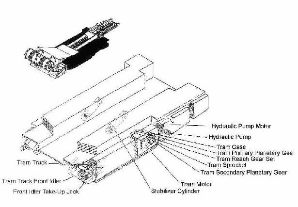
© DBT AMERICA 2005
Technical data
tractor frame—tractor motor figure 2


tram preliminary planetary gear figure-3


© DBT AMERICA 2005
Technical data
tram secondary planetary gear Figure 4

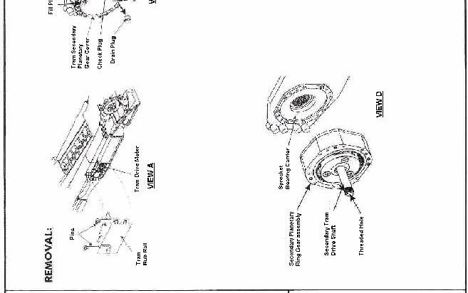
tram case—page 1 of 2 Figure—5


© DBT AMERICA 2005
Technical data
tram case—page 2 of 2 Figure—6
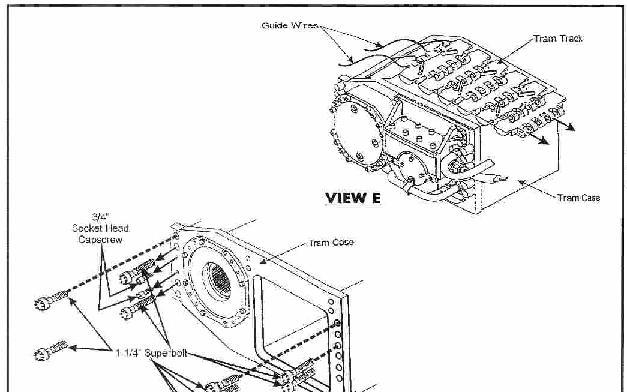
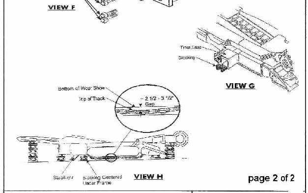
stabilizing cylinder Figure—7
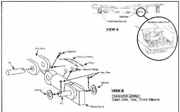

© DBT AMERICA 2005
Technical data
tram sprocket—figure—8
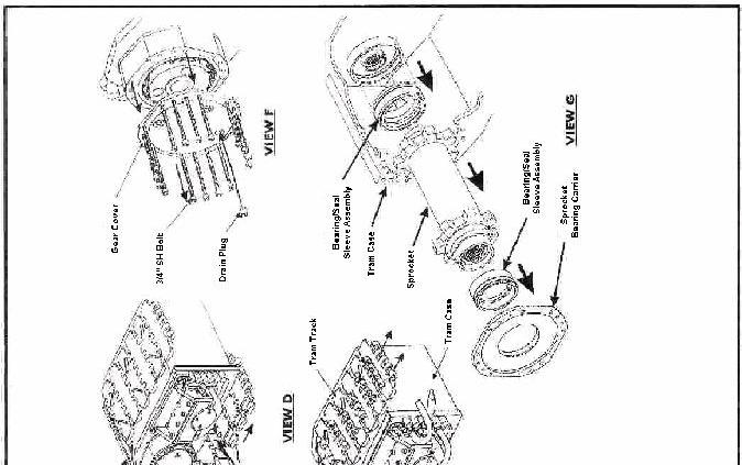
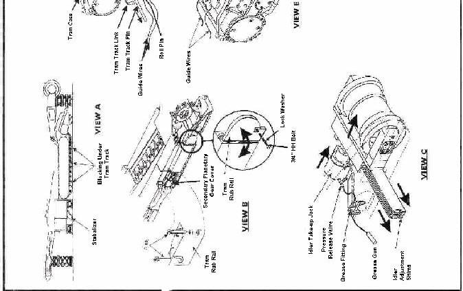
tram track adjustment figure—9


© DBT AMERICA 2005
Technical data
tram track from idler—figure—10


front idler take-up jack figure—11


© DBT AMERICA 2005
Technical data
hydraulic pump figure—12


hydraulic pump motor figure—13


© DBT AMERICA 2005
Technical data
gathering head—figure—14

gathering head assembly figure - 15


© DBT AMERICA 2005
Technical data
gathering head CLA installation / removal Figure—16

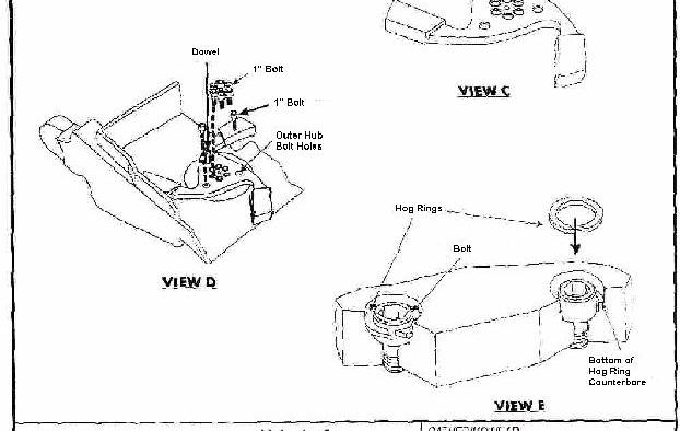


© DBT AMERICA 2005
Technical data

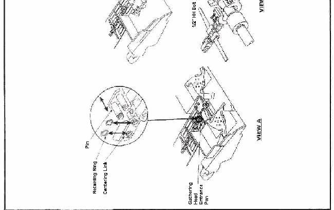
foot shaft assembly—figure—19


© DBT AMERICA 2005
Technical data
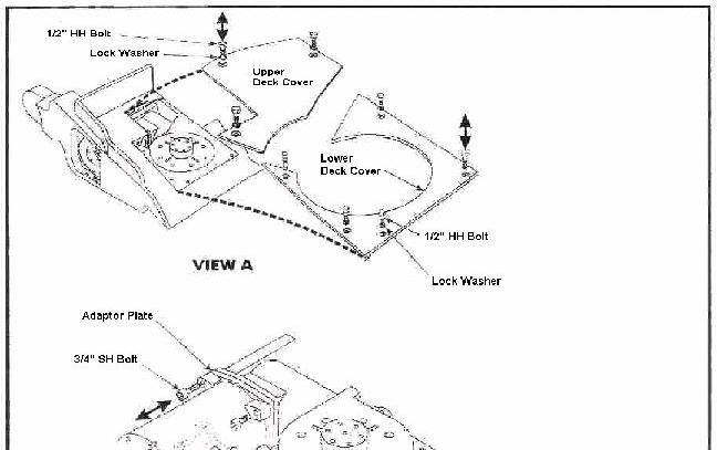

gathering head gear case assembly Figure—21


© DBT AMERICA 2005
Technical data
gathering head gear case assembly Figure—22
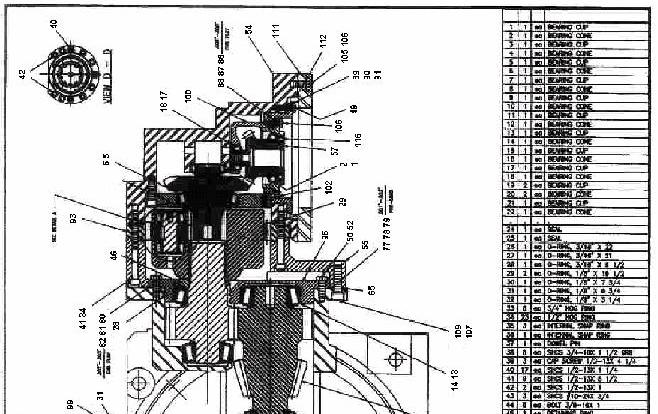

gathering head lift cylinder Installation / removal Figure—23


© DBT AMERICA 2005
Technical data
cutter head assemblies figure—24


cutter head boom assemblies Figure—25


© DBT AMERICA 2005
Technical data
Cutter head dash-0, 1, 2 boom pivot pin Figure 26
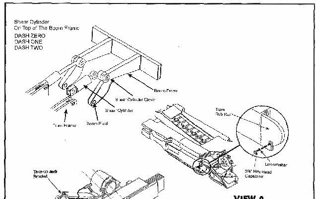
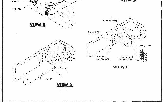
Cutter head dash-3 boom pivot pin Figure—27


© DBT AMERICA 2005
Technical data
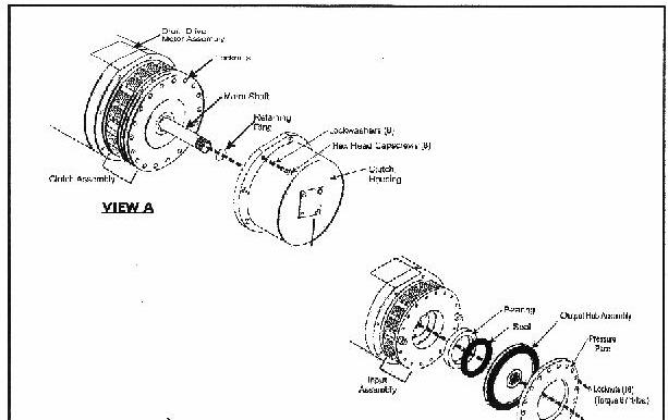

cutter head dash-2, 3 drum drive motor Figure 29


© DBT AMERICA 2005
Technical data
cutter head dash-0, 1 drum drive motor Figure—30

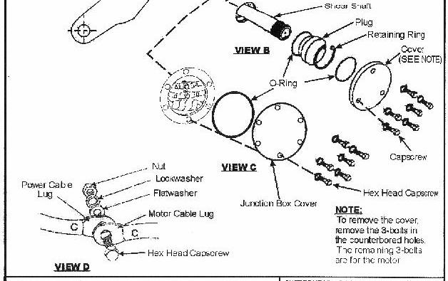
Cutter head dash-0, 1, 2 shear cylinder Figure—32


© DBT AMERICA 2005
Technical data
Cutter head dash-3 shear cylinder Figure—33
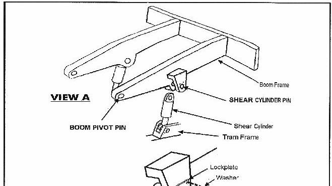
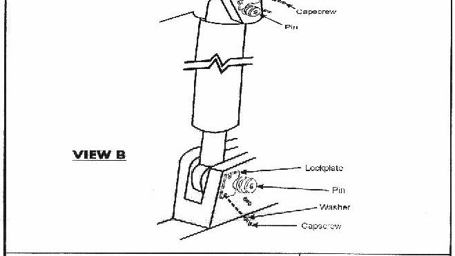
cutter boom dash-0 cutter drums Figure—34
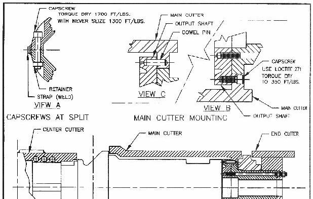
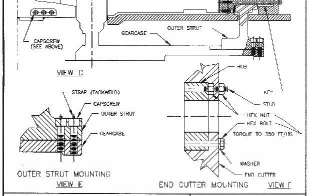
© DBT AMERICA 2005
Technical data
cutter boom dash-1 cutter drums Figure—35
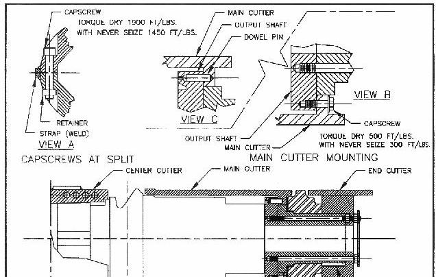

cutter boom dash-2 cutter drums Figure—36


© DBT AMERICA 2005
Technical data
cutter boom dash-3 cutter drums Figure—37

Conveyor—Figure 38

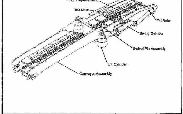
© DBT AMERICA 2005
Technical data
conveyor—figure 39

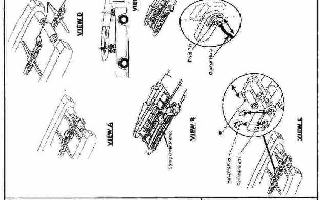
Swing cylinder—figure—40


© DBT AMERICA 2005
Technical data
swivel pin—figure—41
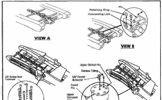
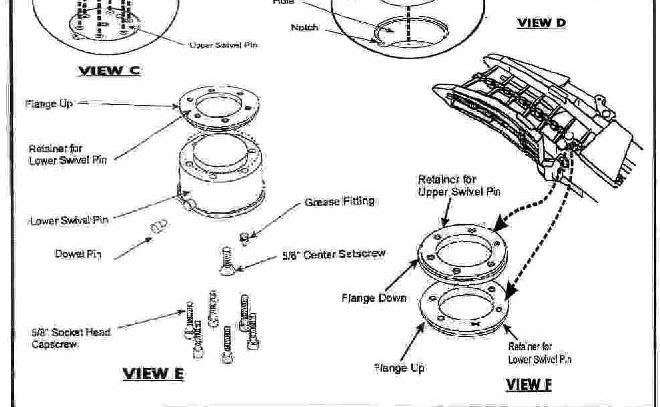
tail roller—figure—42
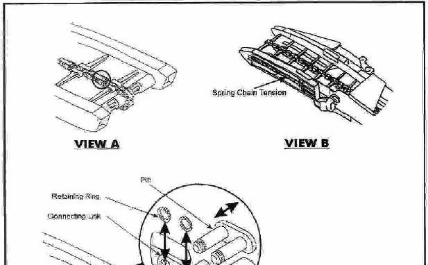

© DBT AMERICA 2005
Technical data
tail shim—figure—43

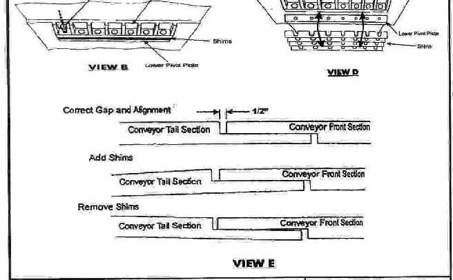
© DBT AMERICA 2005
7For your information

our service
service addresses
If you need to order spare parts, or if technical problems occur, please contact our after-sales service personnel or contact us directly.
DBT America (Warehouse Facility)
DBT America (Rebuild and Service Facility)
DBT America (Manufacturing Facility)
Internet: http://www.dbt.com
© DBT AMERICA 2005