Carefully read personal and machine SAFETY PRECAUTIONS (at the beginning of this manual)
- Use MRM2 grease to lubricate all the hinging.
Lenght of diagonal tie-rod (3) connecting the push arms to the mouldboard can be adjusted to allow quadrature of the push arms with the machine. Finally, at the end of the assembly, when checking sizes (L1 and L2), should (L1) appear to be greater than (L2), it is necessary to lengthen the tie-rod (3): or otherwise shorten it.
- Ball and socket joints (b) for hinging the adjustable tie-rod (1) and the tilt cylinder (T) to the moulboard must be adjusted by means of shims (s) in order to allow the ball freedom of movement with an axial backlash of 0.3-0.6 mm; - Lenght of adjustable diagonal tie-rod (3) must be the same as that of the fixed tie-rod (2). Once this is performed, proceed with assembling the complete equipment. After hinging the boom to the track, pay attention to lay the mouldboard, on a wooden support, by means of the central leverage support so that the rear wall is vertical and the booms are symmetrical as compared with the machine, by measuring sizes L1-L2 between boom and track. - Use fulcrum in (d), to oscillate crosswise first the tie-rod and then the cylinder to check their alignment with the respective seats on the moulboard. - If it appears, upon checking, that connection can take place without forcing, proceed with fastening, paying attention to guarantee a backlash of 0.3-0.6 on the ball, previously set by means of shims (s). - Otherwise, move the push arms by means a lever, until detecting a free connection of the tie-rod and the cylinder, then shim at point (a) by distributing the shims according to the obtained space.
At equipment assembly stage, first of all consider following instruction:
1850K BULLDOZER EQUIPMENT INSTALLATION
e
m
g
C3 C1
d e
L2
L1
3 a
Push arms and bulldozer blade
h
C2
C1
b
m
f
T
1
b
3
2
SM959
g
t
Note – On reassembly grease the threaded ends of the tie rods (1) with Fiat grease MRM2.
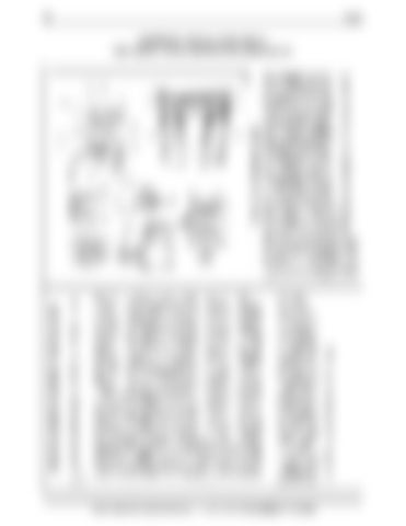
a. Hinge front push arms - b. Front ball hinge side tie rod (1) and cylinder (T) - d. Rear hinge side tie rod (1) and cylinder (T) - e. and f. Diagonal tie rod hinge (2 and 3) - g. Blade control cylinder rod hinges - h. and m. Hinges central blade leverage - Cl. Blade control cylinder - C1. Fixing screws hinge pin plate (e-g), tightening torque 17 ÷ 19 daNm (125 ÷ 140 lb ft) - C2. Fixing screws hinge pin flange (a-f-h), tightening torque 22 ÷ 24 daNm (162 ÷ 177 lb ft) - C3. Fixing screws ball hinge seat (b), tightening torque 22 ÷ 24 daNm (162 ÷ 177 lb ft) - L. = 1206 ÷ 1208 mm (47.48 ÷ 47.55 in). Length of the tie rods (1) to be measured as shown in the illustration - L1. and L2. Check values on reassembly (maximum tolerance 10 mm) - S. Regulator plates ball joint - T. Hydraulic tilt control cylinder - 1. Left hand lateral tie rod for adjusting cutting position and sideways tilting of the blade - 2. Left hand diagonal tie rod connecting blade to push arms - 3. Right hand diagonal tie rod connecting blade to push arms.
f
d
a
S
C2
Cl
h
20 1850K
EQUIPMENT INSTALLATION DECAL "SEE INSTALLATION INSTRUCTION (BUR6-49110)"


