5 minute read
Every 1000 hours work


EVERY 1000 HOURS WORK
ENGINE:
21. FUEL INJECTORS -
Calibrate setting of injectors
DANGER Keep hands away from the tip of injectors, when checking efficiency. Fine sprayed fuel under pressure could penetrate the skin and cause blood poisoning. Also, when checking the efficiency of injectors, wear safety glasses with side shields.
Have the injectors checked by a Service specialized shop.
22. VALVE CLEARANCE -
Check valve clearance, with cold engine
Have the clearance between engine valves and rocker arms checked by specialized personnel. The adjustment of the valve clearance must be done with cold engine.
Valve clearance -Intake .....................................0.30 mm (0.012 in) -Exhaust ..................................0.60 mm (0.024 in)
Valve clearance check
1850-2M0132
23. BEVEL GEAR STEERING AND BRAKES -
Change oil and wash suction filter
Drain oil
Place a container of at least 50 liter (13 USG) capacity under the transmission housing. Remove plug A and let the oil drain completely. Retighten plug A after washing it.
A
A. Steering and brakes oil draining plug.
1850-2M0133
Wash the suction filter and magnetic rod
Tilt the cab, remove plug 1 and pull-out the mesh filter indicated in the figure and the magnetic rod 5. Wash both of them with solvent. Clean inside the body. Re-install the filter, magnetic rod and cover. Check and top-off the oil after changing it.
1 2
3 4
5
F
1850-2M0134
F. Transmission/torque converter suction filter - 1. Nut 2. Cover - 3. Gasket - 4. Mesh filter - 5. Magnetic rod.
Oil filling
Pour in oil up to the prescribed level, indicated by the mark on dipstick 2. Start the engine and let it run at about 1000 rpm. Actuate the steering levers a few times. Stop the engine and after a few minutes check that the oil level reaches the upper mark on the dipstick. Topup, as required, through the plug hole.
24. TORQUE CONVERTER TRANSMISSION
CIRCUIT -
Wash sunction filter and magnetic rod
Tilt the cab, remove plug 1 and pull-out the mesh filter indicated in the figure and the magnetic rod. Wash both of them with solvent. Clean inside the body. Re-install the filter, magnetic rod and cover. Check and top-up the oil after changing it (as described in item 3).
1 2
3 4
5
F
2
1850-2M0136
F. Transmission/torque converter suction filter - 1. Nut 2. Cover - 3. Gasket - 4. Mesh filter - 5. Magnetic rod
1850-2M0115
MIN MAX
1850-2M0135
Dipstick A
The correct oil level must be between the two marks.
25. TORQUE CONVERTER TO TRANSMISSION
PROP SHAFT - Grease (U joints)
Tilt the cab. Pump grease (three or four strokes) into the appropriate fitting to lubricate the spiders.
Note – Perform the operation more frequently when the machine operates in extreme dusty conditions.
Propeller shaft
WARNING Do not run the engine in closed areas without proper ventilation to remove deadly exhaust fumes.
D350M0117
26. BATTERIES - Check electrolyte level
WARNING Batteries contain SULPHURIC ACID. Protect eyes when working on batteries. In the event acid contacts skin, eyes or clothing, WASH IMMEDIATLEY WITH WATER FOR AT LEAST TEN MINUTES.Seek medical help. Should booster batteries be used, remember to connect both ends of the booster cables in the proper manner (+) with (+) and (-) with (-). Avoid short-circuits of the terminals. FUMES ARE FLAMMABLE. Estinguish all smoking materials and free flames, before checking, topping-up or charging batteries. Do not check batteries by shorting.
-Remove the three screws S on rear panel P indicated. -Rotate the panel. -Check that the elecrolyte reaches the reference mark, on the side of the batteries B. -To restore level, top-off with distilled water. -Do not overfill.
S
P CAUTION To maintain batteries in efficient conditions, follow these instructions: -do not leave lights on for extended periods when engine is off or idling; -for short stoppages, it is preferable idling the engine rarther than shutting it off, since each starting can run down the batteries; -make sure the cable terminals are properly secured to battery posts and are covered with a thin layer of petroleum jelly; -keep batteries clean, especially the top; -disconnect the ground cable before touching the terminals.
CAUTION To avoid possible damages to the electrical system: -do not mismatch the terminal connection on batteries; -do not let the engine run when batteries are disconnected; -if batteries are partially discharged and auxiliary batteries are used to start the engine, or in the event of battery charging through external systems, connect terminals of the same sign, (+ to + and - to -).
1850-2M0137
27. AIR CONDITIONER COMPRESSOR -
Check condition of belt and adjust sag
Open the access panel on the left side of the machine. 1. Check the conditions of the compressor belt. In the event the belt is worn or damaged, replace it wit a new one.
The belt must deflect 15 to 20 mm (19/32 to 25/32 in)under as force of 110N (25 lbs). 2. Loosen the compressor mounting bolt and the bracket adjusting screw. 3. To obtain a correct belt adjustment, move the compressor outward. Tighten the compressor mounting bolt and the bracket adjusting screw. 4. If necessary, repeat phases 2 and 3.
28. FAN-ALTERNATOR BELT -
Check condition and sagging of belt, replace
WARNING Do not inspect the tension or adjust belts with the engine running. Be particularly aware of fans. Do not place the head, body, limbs, feet or hands near belts or moving fans. Be particularly aware of blowing fans.
Open the right and left engine panels and inspect the belt. Crosswise cracks on the belt are acceptable. Crosswise cracks combind with longitudinal cracks, fraying, breakage points on the belt are not acceptable. In such a case, replace it.
Measure the belt sag on the long span of the belt that under a pressure of a finger deflects a minimum of 9.5 mm (3/8 in) and a maximum of 12.7 mm (1/2 in). A more accurate inspection can be done using a belt dynamometer located in the middle of the longest span of the belt. Under these circumstances, the tension limits must be included between a minimum of 36 daNm (265 lbft) and a maximum of 49 daNm (361 lbft).
Acceptable condition
Belt to be replaced
1850-2M0138 D350M0178
Inspection of belt tension
1850-2M0122
Replacing a belt
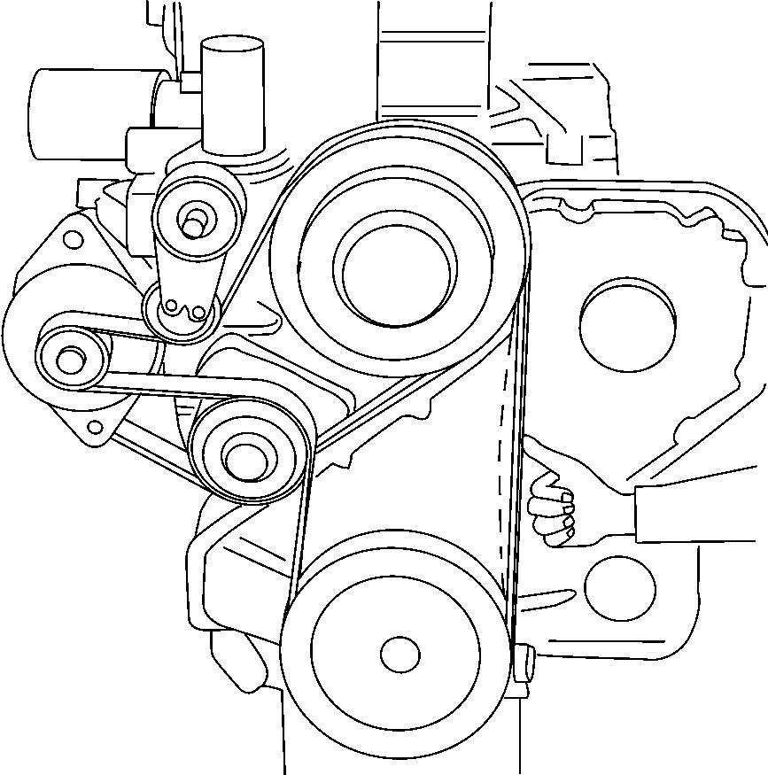
Actuate the tensioner with a leverage and remove the belt. To install a new belt, place it on the fan and crankshaft pulleys, raise the tensioner and complete the turning of the belt, as illustrated. Also, check that the tensioner securing nut is tightened to a torque of 4.3 daNm (31.7 lbft).
Removing the belt
1850-2M0123