www.classicmachinery.net
AVERY A-R-Y-MMBF-MMBG-MMV TBMING GEARS 30. Camshaft gear removal requires remo\al of camshaft. Refer to paragraph 33 for removal procedure. With camshaft removed, press gear off the camshaft towards the rear. When installing a gear on the camshaft, be sure that front face of gear is seated against rear face of camshaft front shoulder. 31. The distributor drive gear (2— Fig. A8) on the front of the camshaft is not a replaceable item. The camshaft and distributor drive gear are furnished as a unit.
Paragraphs 30-37
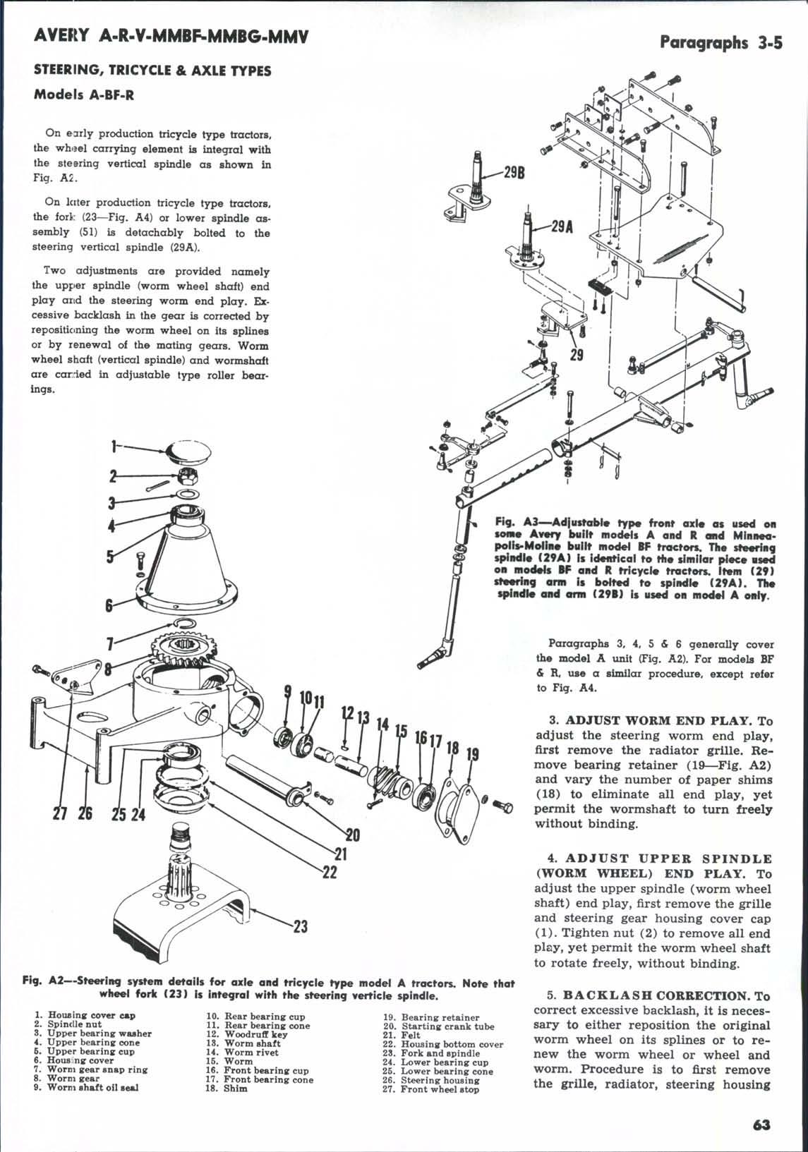
Due to the extremely tight fit of this gear it is almost impossible to pull it from the crankshaft with any of the commercial pullers. If a suitable arbor press is not available or if it is desired to remove the gear without removing the shaft from the engine, Hercules recommends splitting the gear after first drilling through with a V4 inch drill midway between the edge of the keyway and the base of the teeth, A mild application of heat on the crankshaft gear of 450 °F. or when gear turns a pale straw yellow will facilitate its reinstallation. Crankshaft gear backlash should be 0.000 to 0.002.
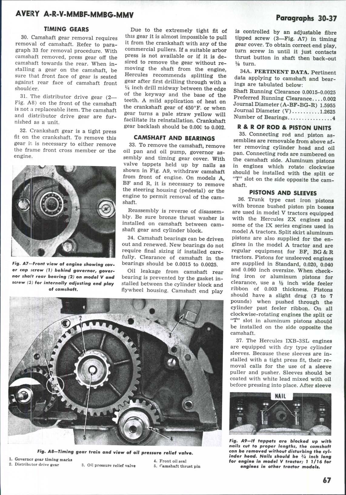
is controlled by an adjustable fibre tipped screw (3—Fig. A7) in timing gear cover. To obtain correct end play, turn screw in until it just contacts thrust button in shaft then back-out Vs turn. 34A. PERTINENT DATA. Pertinent data applying to camshaft and bearings are tabulated below: Shaft Running Clearance 0.0015-0.0025 Preferred Running Clearance... .0.002 Journal Diameter (A-BF-BG-R) 1.5955 Journal Diameter (V) 1.2625 Number of Bearings 4
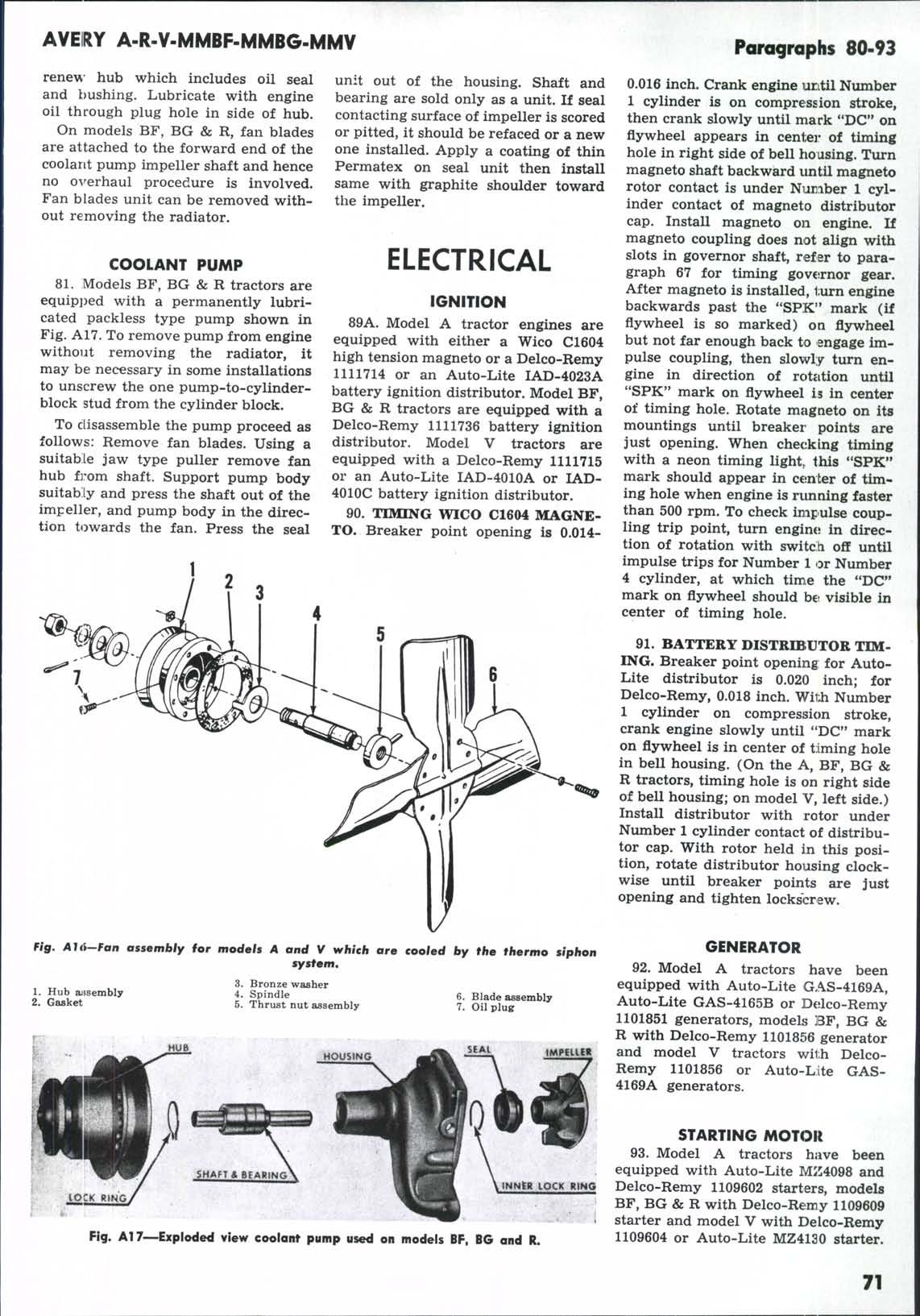
R & R OF ROD & PISTON UNITS 35. Connecting rod and piston asCAMSHAFT AND BEARINGS semblies are removable from above af33. To remove the camshaft, remove ter removing cylinder head and oil oil pan and oil pump, governor as- pan. Connecting rods are numbered on sembly and timing gear cover. With the camshaft side. Aluminum pistons valve tappets held up by nails as in engines which rotate clockwise shown in Fig. A9, withdraw camshaft should be installed with the split or from front of engine. On models A, "T" slot on the side opposite the camBF and R, it is necessary to remove shaft. the steering housing (pedestal) or the PISTONS AND SLEEVES engine to permit removal of the cam36. Trunk type cast iron pistons shaft. with bronze bushed piston pin bosses Reassembly is reverse of disassem- are used in model V tractors equipped bly. Be sure bronze thrust washer is with the Hercules ZX engines and installed on camshaft between cam- some of the IX series engines used in shaft gear and cylinder block. model A tractors. Split skirt aluminum 34. Camshaft bearings can be driven pistons are also supplied for the enout and renewed. New bearings do not gines in the model A tractor and are require final sizing if installed care- regular equipment for BF, BG & R fully. Clearance of camshaft in the tractors. Pistons for unsleeved engines are supplied in Standard, 0.020, 0.040 Fig. A7—Front view of engine showing cov- bearings should be 0.0015 to 0.0025. er cap Ecrew (1) behind governor, goverOil leakage from camshaft rear and 0.060 inch oversize. When checknor shait rear bearing (7) on model V and bearing is prevented by the gasket in- ing iron or aluminum pistons for clearance, use a ^ inch wide feeler screw (3) for internally ad'iusting end play stalled between the cylinder block and of camshaft. fiywheel housing. Camshaft end play ribbon of 0.003 thickness. Pistons should have a slight drag (3 to 7 pounds) when pushed through the cylinder past feeler ribbon. On all clockwise-rotating engines the split or "T" slot in aluminum pistons should be installed on the side opposite the camshaft. 32. Crankshaft gear is a tight press fit on the crankshaft. To remove this gear ii; is necessary to either remove the frame front cross member or the engine.
37. The Hercules IXB-3SL engines are equipped with dry type cylinder sleeves. Because these sleeves are installed with a tight press fit, their removal calls for the use of a sleeve puller and pusher. Sleeves should be coated with white lead mixed with oil before pressing into place. After sleeve
fig, AS-Timing gear train and view of oil pressure relief valve 1. Governcr gear timing marks 2. Distributor drive gear
3. Oil pressure relief valve
4. Front oil seal 6. Hamshaft thrust pin
Fig, 49—/f tappets are blocked up with nails cut to proper lengths, the camshaft can be removed without disturbing the cylinder head. Nails should be V4 inch long for engine In model V tractor} I 1/16 for engines in other tractor modeh*
67