3 minute read
Front wheel stop

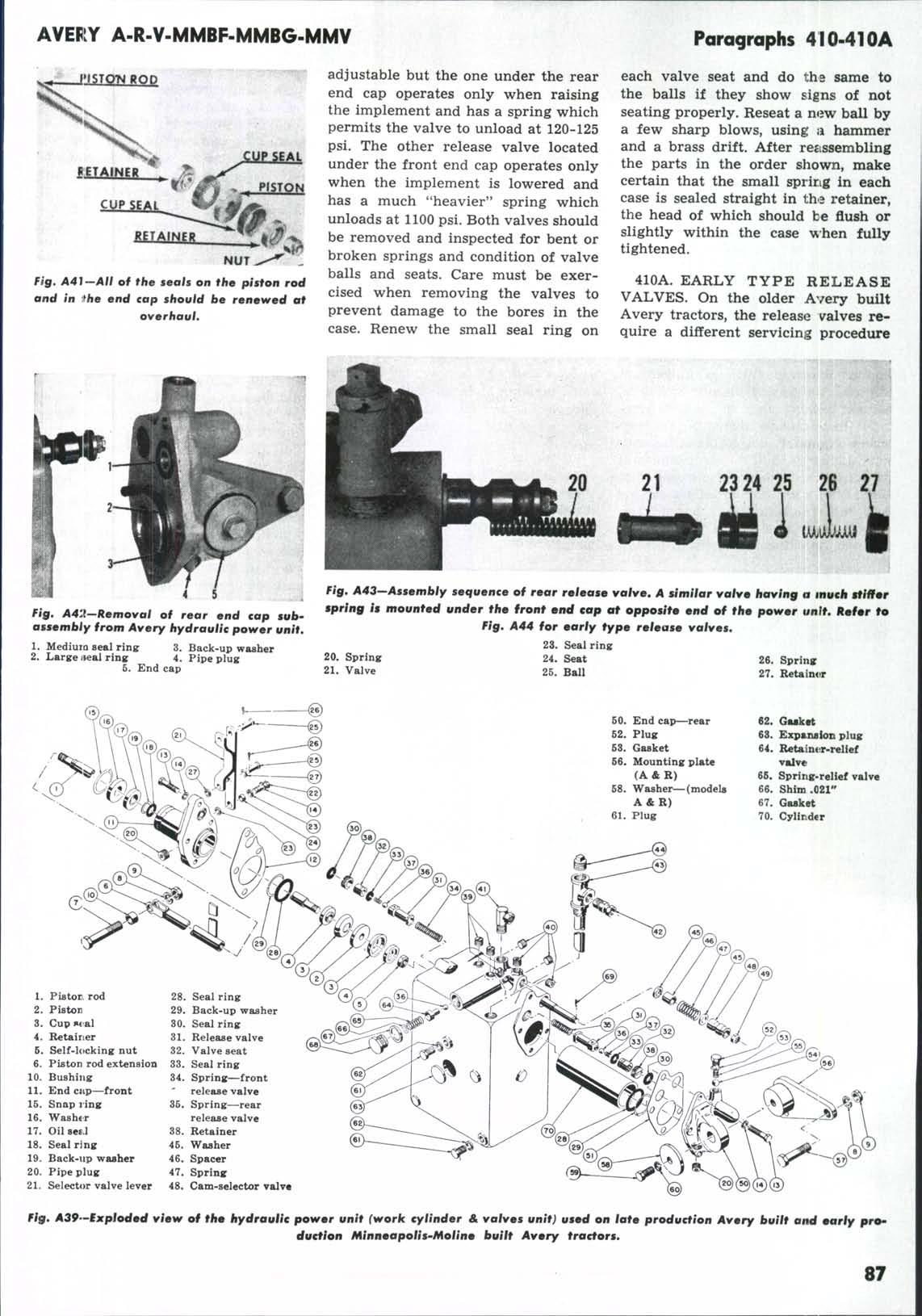
than outlined in paragraph 410. With the unit off the tractor and both end caps removed, tip the assembly so that the pipe spacer, valve, light spring and ball will fall out. Using care to prevent damaging the bore, insert a drift or rod into the opening and push the remaining parts. Fig. A44, out through the front of the unit. Check the springs, balls and seats for wear and renew any that are worn or damaged. Remove the *'O'* ring seal from each seat and install new ones. Reseat a new ball by a few sharp blows, using a hammer and a brass drift.
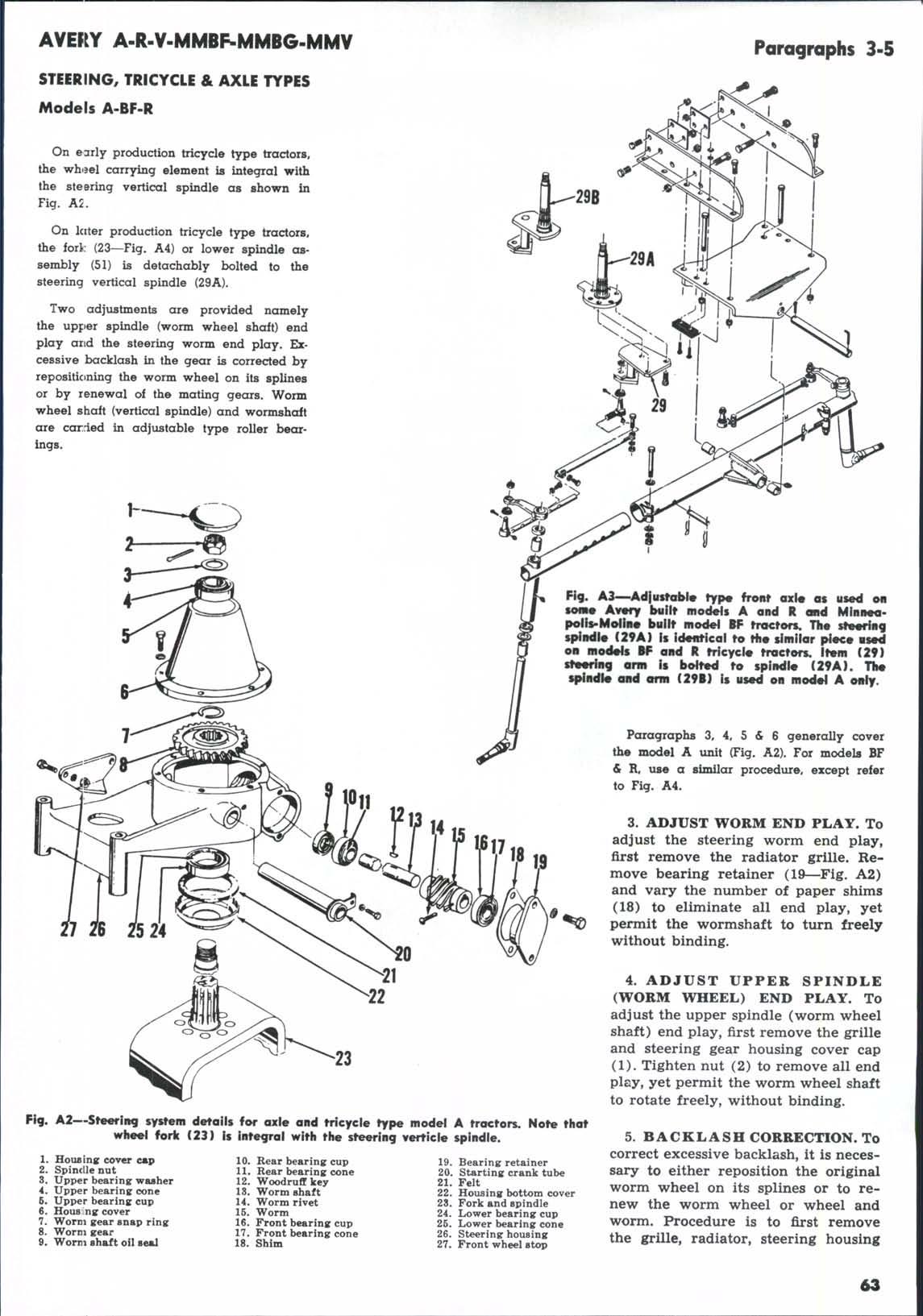
410B. Procedure for reassembling is to first remove the two pipe plugs from the rear top side of the unit Fig. A45. Obtain a short piece of metal tubing, 9/16 inch outside diameter, Vz inch inside diameter. Select the valve seat with the larger hole, oil the inside wall of the tubing and place this seat into the tubing with the slotted end of the seat to the outside. Insert a small rod into the rear pipe plug hole and push the seat into the bore until it strikes the rod. Hold the seat in place with a small punch then remove the tubing. Install the ball, light spring, valve and pipe spacer into the bore and reinstall the unit rear end cap.
410C. Assemble the plunger into the plunger housing. Using a small piece of 0,002 shim stock, place these parts into the piece of metal tubing as shown. Function of the shim stock is to prevent damaging the *'O'* ring seal when it passes the pipe plug hole. Install these parts into the bore from the front of the case and remove the shim stock and piece of tubing. Using the same procedure outlined in paragraph 410B, install the seat which has the small opening, then insert the ball, the large spring and the valve in that order. Install the front end cap to the unit.
411. SELECTOR VALVE AND
CAM. The valve and cam unit can be lifted from the case after the rear end cap has been removed as outlined in paragraph 409.
30
31 32 33 34 35 36 37 38 39 40
fl^, A44—Assembly sequence of early type release valves used in Avery built Avery tractors having the solid (non-pivoted) mounting of the power unit,
50. Pipe spacer 37. Seat 51. Valve S4. Seat 38. Ball 82. Spring S&. Plunger 39. Spring S3. Ball 86. Plunger botuins 40. Valv«
With valve Fig. A46 removed, thoroughly and carefully clean the bore in the case and the valve. If valve is roughened or scored, it should be renewed. To remove the cam from the valve, first insert a 1/4 inch drift or rod into the hole in the valve then remove the cotter pin. When removing the nut be careful as the releasing of the spring pressure may send the parts fiying. The oil and dust cover seal located in the case at opposite end of the selector valve bore should be removed and a new one installed. Open end of seal should face to the inside.
412. RELIEF VALVE. The relief valve. Fig. A47 on all models, can be serviced without removing the valves and work cylinder unit from the tractor. To test the valve, remove the pipe plug from one of the end caps and install in its place a pressure gauge of 2000 pounds or higher capacity as shown in Fig. A48. Start the engine and operate the work cylinder a few times then run the piston to the opposite end of the unit. Hold the selector control so that it tries to force the piston even further in this direction and note the gauge reading. The reading should be 1400-1600 psi. If reading is less than 1400 add shims (4—Fig. A47) until this reading is obtained. If reading is higher than 1600, remove a shim or shims.
Piff. A45—Recommencl- •if mefliocf for assent* bling old style release valves involves the use of a piece of steel tubing and a strip of shim stock,
X. Rear pipe hole 41. Plunger housing 42. Metal tube 43. Shim stock (0.002)
8
fig, A47—Components of relief valve sembly contained in power unit,
1. Ball S. Spring 5. Gasket 2. Relief valve 4. Shim 6. Plug
fig. A46—Assembly sequence of selector valve and cam assembly* The cam need not be removed from valve unless the valve is to be rmnowmd. 46. Selector valve 46. Waaher 47. Spring 48. Spacer 50. Selector cam 61. Nut fig. A48^Using a pressure gauge to tmti hydraulic system relief valve without re* moving power unit from tra€tor*