4 minute read
Rear bearing cone

CLUTCH
All late models are equipped with Rockford spring loaded single plate clutches. The 9-inch Rockford RM is used in models A, BF, BG & R and the 8-inch RM in the model V. Clutch lingers are adjustable, but should not be changed from the original adjustment, except when the clutch is being overhauled. Compensation for lining wear is obtained by restoring the pedal free travel as outlined in next paragraph. The clutch shaft, clutch shaft rear bearing and the clutch release bearing and the operating yoke are all carried in the clutch housing, which is bolted to the rear face of the flywheel housing. There are no inspection openings in the clutch housing.
NOTE: Some early model A tractors were equipped with a Long 9CF clutch.
CLUTCH PEDAL ADJUSTMENT
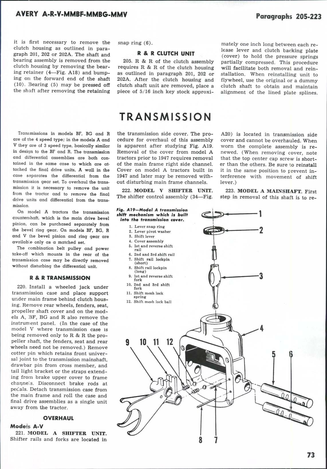
200. When the clutch is new or has just been relined, the clutch pedal should have approximately 1% inches free travel (1—Fig. A18), before the release bearing first contacts the release levers of the clutch unit. As the clutch wears the free travel will become less, but it should not be allowed to go lower than % inch. Insufficient free travel may permit the release yoke to rub against the back face of the clutch and under conditions of zero free travel, the release bearing will rotate continuously and thus wear out prematurely, or the clutch may slip due to being partially disengaged. Too much free travel will prevent complete disengagement of the clutch. It is necessary, therefore, to have some pedal free travel although it need not be as much as 1% inches, except when the clutch is in new condition.
Free travel is adjusted by varying the length of the release rod (15) attached to the clutch pedal. This is accomplished by turning the clevis (16) at the pedal end of the rod after first -emoving the pedal from the tractor. Do not adjust the clutch unit release levers, except when the clutch is removed from the tractor during overhaul.
CLUTCH HOUSING Models A-R
201. To R & R the clutch housing, remove the fuel tank and tank support. Remove the propeller shaft assembly by removing cotter pin from either joint, and sliding same on to propeller shaft splines far enough to disengage opposite end of joint. Remove propeller shaft and the pressed steel shaft cover over the propeller shaft. Disconnect clutch release rod from pedal. Remove clutch housing to flywheel
housing bolts and withdraw the hous
ing and clutch shaft and release bearing assemblies as a single unit. When reinstalling propeller shaft assembly be sure that it is assembled with the universal joint journal cap screws of each joint nearest the adjacent end of the propeller shaft. If cap screws are nearest the center of the shaft, the assembly cannot be collapsed (shortened) enough to permit installation to tractor.
Model V
202. Universal joints on this tractor are welded to the propeller shaft, thus it cannot be collapsed for removal and installation. To R & R the clutch housing, first detach the transmission—differential housing from the tractor main frame and move the rear portion of the tractor backward as per paragraph 220. Slide the propeller shaft and joints unit off the clutch shaft. Removal of the clutch housing from this point on is the same as for the model A as per paragraph 201.
Models BF-BG
202A. Disconnect choke control , governor control and hydraulic reservoir vent tube. Disconnect battery cable at starter, oil line at gage, temperature gage at engine and wiring harness at generator, coil, relay starter and ammeter. Remove hydraulic reservoir and support, instrument panel
and bolts attaching frame channels to engine. Unbolt torque tube from frame channels. Remove steering wheel and steering shaft support, disconnect brake rods, and remove clutch pedal, fuel tank and fuel tank support. Support both halves of tractor, roll rear half of tractor rearward approximately five inches or until front universal joint is free from clutch shaft. Remove the clutch housing retaining bolts, turn housing until notch in right side lines up with top edge of main frame channel and remove clutch housing and clutch shaft assembly.
When reassembling, reverse the removal procedure.
RELEASE BEARING
203. To renew the clutch release bearing, first remove the clutch housing as outlined in paragraph 201, 202 or 202A. Remove hairpin lock from clutch release fork shaft (7—Fig. A18), and then remove fork shaft from clutch housing. Disconnect clutch release rod (15) from the release fork or yoke (8) and withdraw the bearing and sleeve (11) unit from the housing. The bearing may be renewed by pressing it off the sleeve.
SHAFT AND REAR BEARING
204. To renew the clutch shaft and/or the clutch shaft rear bearing,